EP2644242A1 - Filtereinheit, die eine Filterkartusche umfasst, und entsprechende Filterkartusche - Google Patents
Filtereinheit, die eine Filterkartusche umfasst, und entsprechende Filterkartusche Download PDFInfo
- Publication number
- EP2644242A1 EP2644242A1 EP13161649.2A EP13161649A EP2644242A1 EP 2644242 A1 EP2644242 A1 EP 2644242A1 EP 13161649 A EP13161649 A EP 13161649A EP 2644242 A1 EP2644242 A1 EP 2644242A1
- Authority
- EP
- European Patent Office
- Prior art keywords
- filter
- shutter member
- shutter
- filter assembly
- tube
- Prior art date
- Legal status (The legal status is an assumption and is not a legal conclusion. Google has not performed a legal analysis and makes no representation as to the accuracy of the status listed.)
- Granted
Links
Images


Classifications
-
- B—PERFORMING OPERATIONS; TRANSPORTING
- B01—PHYSICAL OR CHEMICAL PROCESSES OR APPARATUS IN GENERAL
- B01D—SEPARATION
- B01D35/00—Filtering devices having features not specifically covered by groups B01D24/00 - B01D33/00, or for applications not specifically covered by groups B01D24/00 - B01D33/00; Auxiliary devices for filtration; Filter housing constructions
- B01D35/14—Safety devices specially adapted for filtration; Devices for indicating clogging
- B01D35/147—Bypass or safety valves
-
- B—PERFORMING OPERATIONS; TRANSPORTING
- B01—PHYSICAL OR CHEMICAL PROCESSES OR APPARATUS IN GENERAL
- B01D—SEPARATION
- B01D35/00—Filtering devices having features not specifically covered by groups B01D24/00 - B01D33/00, or for applications not specifically covered by groups B01D24/00 - B01D33/00; Auxiliary devices for filtration; Filter housing constructions
- B01D35/16—Cleaning-out devices, e.g. for removing the cake from the filter casing or for evacuating the last remnants of liquid
-
- B—PERFORMING OPERATIONS; TRANSPORTING
- B01—PHYSICAL OR CHEMICAL PROCESSES OR APPARATUS IN GENERAL
- B01D—SEPARATION
- B01D2201/00—Details relating to filtering apparatus
- B01D2201/04—Supports for the filtering elements
- B01D2201/0415—Details of supporting structures
-
- B—PERFORMING OPERATIONS; TRANSPORTING
- B01—PHYSICAL OR CHEMICAL PROCESSES OR APPARATUS IN GENERAL
- B01D—SEPARATION
- B01D2201/00—Details relating to filtering apparatus
- B01D2201/16—Valves
- B01D2201/162—Valves with snap, latch or clip connecting means
-
- B—PERFORMING OPERATIONS; TRANSPORTING
- B01—PHYSICAL OR CHEMICAL PROCESSES OR APPARATUS IN GENERAL
- B01D—SEPARATION
- B01D2201/00—Details relating to filtering apparatus
- B01D2201/29—Filter cartridge constructions
- B01D2201/291—End caps
- B01D2201/295—End caps with projections extending in a radial outward direction, e.g. for use as a guide, spacing means
-
- B—PERFORMING OPERATIONS; TRANSPORTING
- B01—PHYSICAL OR CHEMICAL PROCESSES OR APPARATUS IN GENERAL
- B01D—SEPARATION
- B01D2201/00—Details relating to filtering apparatus
- B01D2201/30—Filter housing constructions
- B01D2201/301—Details of removable closures, lids, caps, filter heads
- B01D2201/305—Snap, latch or clip connecting means
-
- B—PERFORMING OPERATIONS; TRANSPORTING
- B01—PHYSICAL OR CHEMICAL PROCESSES OR APPARATUS IN GENERAL
- B01D—SEPARATION
- B01D2201/00—Details relating to filtering apparatus
- B01D2201/31—Other construction details
- B01D2201/316—Standpipes
-
- B—PERFORMING OPERATIONS; TRANSPORTING
- B01—PHYSICAL OR CHEMICAL PROCESSES OR APPARATUS IN GENERAL
- B01D—SEPARATION
- B01D2201/00—Details relating to filtering apparatus
- B01D2201/34—Seals or gaskets for filtering elements
Definitions
- the invention relates to the field of designing and producing filter assemblies used for filtering fluids circulating in engines or hydraulic equipment.
- Such filtering assemblies consist of a filter body, comprising a tank and a lid, inside which is arranged a filtration cartridge comprising a filtering medium generally having a cylindrical shape surrounding a tubular lumen, which can for example be paper, cardboard or felt or other porous material, such as a synthetic nonwoven material.
- the filtration cartridge also comprises two end flanges delimiting the filtration medium.
- Such filter cartridges generally cooperate with a tube, in particular a central tube, integral or not with flanges, the outside diameter of which is close to the inside diameter of the tubular lumen surrounded by the filtering medium, so as to limit the deformations of the medium under the effect the pressure exerted inside the filter assembly.
- the end flanges are formed by a first flange, which may consist of an upper flange, and a second flange, which may consist of a lower flange.
- the role of the flanges is to participate in the sealing of the filter cartridge and to allow the fastening of the filter cartridge to the permanent part of the filter assembly.
- the patent US 5,770,054 discloses a filter assembly whose central tube houses a valve plug member and a return member while the filter cartridge in its upper flange defines a valve seat surface surrounding an opening.
- the shutter member is arranged to engage the valve seat in a closed position.
- the valve seat is replaced, while the shutter member and the return member remain permanently on the central tube.
- a The disadvantage of such a system is that the shutter element in the shutter area is dirty and the rest even with the change of the filter cartridge.
- the invention therefore particularly aims to overcome all or part of these disadvantages of the prior art.
- the invention aims to provide a filtering assembly that is efficient, while limiting the cost of maintenance and replacement of the filter cartridge.
- the invention also aims to provide a filter cartridge incinerable, especially free of metal parts.
- the invention also aims to provide a filter cartridge that is adaptable to threshold pressures opening different valves, without changing the rest of the filter assembly.
- the object of the invention is therefore to provide the user with the possibility of choosing a type of filter cartridge, according to the desired valve opening pressure, without modifying the permanent part of the set of filtering.
- the filter cartridge comprises both the shutter member and the valve seat so that this set of two parts soiled during use of the filter assembly is replaced with the cartridge. filtration.
- the return member belongs to the permanent part of the filter assembly, as is the filter body and the particular central tube located inside the filter body.
- Another advantage of the invention is that the only modification of the dimensions of the shutter element can make it possible to modify the threshold pressure of opening of the valve formed by the valve seat, the shutter member and the return member, depending on what the user wants, without touching the permanent part of the filter set.
- the same set of filtering will thus be modified in its performance, without having to modify the permanent part but only the removable part of the filter assembly, namely the filter cartridge.
- the first flange comprises an opening, in particular a circular opening, in which the shutter element is retained while being movable in translation between a position corresponding to the closed position and a position corresponding to an open position. of the valve.
- the first flange and the shutter member cooperate to allow the shutter member to perform its function of opening and closing the valve, depending on the pressure exerted by the fluid on the shutter member and in response, the force of the return member exerted opposite on the shutter member. It is the return member that forces the shutter member into the closed position when the pressure exerted on the opposite side on the shutter member is less than a predetermined pressure threshold.
- the opening may for example be delimited by a tubular portion and a projecting element of the shutter member may abut against an inner shoulder of the tubular portion during assembly.
- This makes it possible to set a limit to the opening of the shutter element in the maximum open position, during assembly, and to retain the shutter element on the first flange and thus on the filtration cartridge. In use, this maximum opening may not be reached, a clearance that can be provided between the shutter member and the projecting element.
- the shutter member may for example be retained in support by the tube to spare this game and prevent the shutter member to reach the maximum open position.
- the opening may, in this case in particular, be at least partially confused with the orifice passing through the valve seat and closed by the shutter element in its closed position.
- valve seat may be one of several orifices, or of a single orifice, closed by the sealing surface when the shutter element is in the closed position. or closing position.
- the opening is distinct from the at least one orifice passing through the valve seat and through which the fluid can pass, in the open position of the shutter member.
- the shutter member may comprise a skirt having the sealing surface adapted to come into contact with the valve seat, in the closed position of the shutter member.
- the tube may be at least partially hollow and the return member may be mounted in the tube.
- the return member comprises a spring, in particular a helical spring.
- the invention is however not limited to a coil spring.
- the return member may comprise a leaf spring or an elastic material.
- the tube of the filter assembly may have a free end forming at least partially an edge extending diametrically inwardly so as to retain the return member abutting against said edge.
- the tube may alternatively comprise, in a free end portion, a housing configured to receive and hold the return member, without however preventing it from fulfilling its function of returning the shutter member to the position of closing.
- the shutter member may comprise a zone of cooperation with the return member, comprising a bearing surface of the return member and / or a guide region of the return member.
- the shutter member comprises, according to one embodiment of the invention, a zone of attachment with the first flange, a valve seat sealing zone and a cooperation zone with the return member.
- the filter body advantageously comprises a tank and a lid comprising means of cooperation between them sealed but removable, so as to allow the replacement of the filter cartridge.
- the filtration medium may be chosen from the group consisting of: cellulose, in particular paper or cardboard, felt, a woven or non-woven porous material, synthetic or not, and any other suitable filtration medium.
- the shutter member may comprise a polymeric material, in particular polyamide.
- the shutter element is made of a material that is incinerable.
- the invention further relates, in combination with the foregoing, a filtration cartridge for filter assembly as defined above.
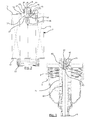
- a filter assembly 1 for fluid flowing in an engine or hydraulic equipment.
- This filter assembly 1 comprises a filter body 2 comprising a tank 3 and a cover 4.
- the filter body 2 defines a volume 5 inside which the filter assembly 1 comprises a tube 6, central in this example.
- the filter assembly 1 also comprises a filtration cartridge 7 shown in isolation on the figure 2 .
- the tank 3 is provided with an internal thread 8 and the lid 4 is provided with a external thread 9 adapted to be screwed on the internal thread 8 of the tank 3 so as to close the filter assembly 1.
- the sealing of the filter assembly 1 is further ensured by at least one annular seal 10, inserted between the lid 4 and the tank 3. It is thus relatively easy to unscrew the lid 4 and the tank 3 of the filter body 2 in order to extract the filter cartridge 7 when it is used to replace it with a cartridge filtration 7 new.
- the filtration cartridge 7 comprises a first flange 11, said upper flange, and a second flange 12, said lower flange.
- the filter cartridge 7 further comprises a filtering medium 13, of generally cylindrical shape, having a tubular lumen 14 for surrounding the tube 6, as illustrated in FIG. figure 1 .
- the filtration medium 13 extends longitudinally, along a longitudinal axis X, between the first flange 11 and the second flange 12.
- the first flange 11 comprises a valve seat 15 through which an orifice 16 communicates with the tubular lumen 14.
- the second flange 12 integrates into a housing an O-ring 22 forming the seal in the lower part of the filtration cartridge 7.
- the tube 6 has an outer relief consisting, in this example, of a plurality of fins 71 inclined to retain the filtering medium 13 while allowing the passage of fluid.
- the tube 6 is secured to the tank 3 of the filter body 2 in the lower part thereof, in particular by snapping or other, the seal being provided by the presence of visible joints in these figures including the seal 22, in this example .
- the filtration cartridge 7 further comprises a shutter member 20 secured to the first valve flange 11 and adapted to cooperate with the valve seat 15.
- the shutter member 20 is thus configured to occupy two positions, namely a closed position in which the shutter member 20 closes the valve seat 15 and at least one open position in which the shutter member 20 allows the passage of fluid through the valve seat 15.
- the filter assembly 1 further comprises a return member 21 formed in this example by a spring, separate from the filter cartridge 7, and configured to act by returning the shutter member 20 in the closed position.
- the filter assembly 1 comprises a permanent part comprising the filter body 2, the tube 6 and the return member 21, and a removable part comprising the filtration cartridge 7 comprising the first and second flanges 11 and 12, the filtration medium 13 and the shutter element 20.
- the safety valve formed of the following three elements, namely the valve seat 15, the shutter member 20 and the return member 21 consists partly of removable elements forming part of the filtration cartridge 7, namely the valve seat 15 and the shutter member 20 and partly permanent elements, namely the return member 21, which remains permanently during the replacement of the filter cartridge 7 .
- An advantage of the filter assembly 1 according to the invention is that it makes it possible to completely replace the closure zone formed by the zone of contact, between the valve seat 15 and the shutter element 20, which can be contaminated with the use of the filter assembly 1. This dirty area will be completely replaced by a clean contact area when replacing the filter cartridge 7.
- the return member 21 remains permanently in the filter assembly 1 and is not replaced so that the number of parts constituting the filter cartridge 7 is limit.
- the return member 21 may indeed be soiled, but this does not interfere with the operation of the engine.
- the return member 21 may be at least partially metallic.
- the filtration cartridge 7, devoid of metal part, is incinerable.
- the first flange 11 comprises a tubular portion 25, central in this example, at least partially hollow, extending, in the illustrated example, around an opening corresponding to the orifice 16. A inside this tubular portion 25 and in this opening, the shutter member 20 is retained while being movable in translation along the longitudinal axis X between a position corresponding to the closed position and a position corresponding to an open position of the valve.
- the shutter member 20 comprises at least one projecting element 26, consisting of a plurality of tongues in the illustrated example, which can abut against an inner shoulder 27 extending around the periphery of the tubular portion 25, internally.
- the shutter member 20 further comprises a skirt 30 extending circumferentially outwardly, substantially perpendicular to the axis X.
- the skirt 30 has the sealing surface 31 adapted to come into contact with the valve seat 15 in the closed position of the closure element 20.
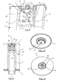
- the tube 6 has a free end 40 forming at least partially an edge 41 extending diametrically, as visible on the Figures 6 and 7 , inwardly so as to retain the return member 21, in this case the spring, abutting against this edge 41 by its first end 42.
- the edge 41 consists, in this example in the end of an upward extension formed here of four rods 72, as shown and partially visible on the Figures 6 and 7 especially. The presence of these rods 72 gives some elasticity to this portion of the tube 6. It could however be otherwise without departing from the scope of the invention.
- the opposite end or second end 43 of the return member 21 is held inside the tube 6, as shown in FIG. figure 7 .
- four lugs 70 present on an inner surface of the tube 6, two of which are visible on the Figures 6 and 7 , allow the retention in the lower part, at the second end 43, of the return member 21.
- the skirt 30 comprises, besides the closure surface 31 and opposite it, a contact surface 32 with the edge 41 of the tube 6.
- the shutter element 20 again in this illustrated example, comprises a guide zone 35 of the return member 21.
- the zone of attachment of the shutter element 20 to the first flange 11 is on one side of the skirt 30 corresponding to the sealing surface 31, while the guide zone 35 of the return member 21 is located on the opposite side of the skirt 30, on the side of the contact surface 32.
- the shutter element 20 also comprises a bearing surface 45, visible in particular on the Figures 4 and 5 , forming in this example a shoulder perpendicular to the longitudinal axis X extending around the guide zone 35.
- This bearing surface 45 is the contact zone, in this circular example, between the shutter member 20 and the return member 21.
- the shutter element 20 also comprises a pressure zone 44, this zone being in contact with the fluid tending to open, by a pressure P, the valve and to place the shutter element 20 in the open position.
- the pressure zone 44 is illustrated on the figure 2 by a double arrow extending over the entire contact area between the fluid tending to open the valve and the shutter member 20. This pressure zone 44 extends in this example, as visible, substantially perpendicular to the X axis according to a diameter corresponding to that of the orifice 16.
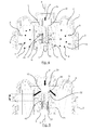
- FIGS 4 and 5 illustrate the operation, schematically, of the safety valve formed by the valve seat 15, the shutter member 20 and the return member 21.
- the figure 5 illustrates the case where the safety valve is open, in the case of cold fluid, especially cold oil, whose viscosity is such that it can not pass through the filtration medium 13, in which case it forces, by the pressure P that it exerts on the pressure zone 44 of the shutter member 20 to place it in an open position of the valve, so as to flow.
- the shutter member 20 also passes in the open position. It should be noted that in the open position illustrated on the figure 5 , the contact surface 32 comes into contact with the edge 41 of the tube 6 while the bearing surface 45 comes against the return member 21 in its upper part, as visible. The fluid passes through the open valve as shown in this figure.
- the figure 4 illustrates the cartridge in operation, at the end of its life.
- D debris is present, as illustrated on the figure 4 around the closure surface 31 which can create a leak L also illustrated in this figure, the pressure P exerted on the shutter member 15 by the fluid is counteracted by the force exerted by the return member 21 of such so that despite the leak L, the shutter member 20 is in the closed position.
- the pressure P does not reach, in this configuration, the predetermined pressure threshold to allow opening of the valve plug member.
- a dirty fluid enters the arrows A in the filtering medium 13 externally, the dirty fluid being illustrated by dark particles M.
- the filtered, clean fluid illustrated by clear N particles, then enters the tube 6 and flows downward along the arrow O.
- the opening threshold pressure from which the shutter element 20 opens can be modulated by widening more or less the diameter R of the pressure zone 44 of the shutter element 20, visible on the figure 2 . By increasing this diameter, the opening pressure threshold necessary for the opening of the valve or valve is reduced. On the contrary, by decreasing it, the opening threshold pressure necessary for the opening of the valve is increased.
- the length H along the longitudinal axis X of the shutter element 20, visible on the figure 5 , between the contact surface 32 and the bearing surface 45 may be modified so as to modulate the threshold pressure necessary to allow the opening of the valve, that is to say the displacement of the shutter member 20 in an open position.
- the shutter element 20 after mounting the filtration cartridge 7 in the permanent part of the filter assembly 1, the shutter element 20 never reaches, in this example, the maximum open position illustrated on FIG. the figure 2 when the filtration cartridge 7 is not yet mounted on the rest of the filter assembly 1. Indeed, once the filter cartridge 7 mounted, the dimensions of the elements are chosen so as to provide a clearance between the inner shoulder 27 of the first flange 11 and the projecting element 26, due to the retention formed by the edge 41 against the contact surface 32.
- the tube 6 comprises, in a free end portion 50, a housing 51 configured to house and hold the return member 21.
- This housing 51 has a bottom wall 52, perpendicular to the axis X, cutting the tube 6 in its length.
- the first flange 11 has a plurality of openings 55 and 60.
- One of these openings, 55 central, allows the retention of the shutter member 20 while leaving it movable in translation between a corresponding position at the closed position and a position corresponding to an open position.
- a plurality of visible openings 60 are arranged, in particular on the figure 11 , three in the example illustrated, forming the fluid passage when the shutter member 20 is in the open position. These openings 60 are peripherally formed around the opening 55.
- the skirt 30 has on one side the sealing surface 31 and, on the opposite side, the contact surface 45 with the return member 21.
- the opening 55 in the first flange 11 allowing the retention of the shutter member 20 is distinct from the orifices 60 allowing the passage of fluid in the absence of shutter is ie in the open position.
Landscapes
- Chemical & Material Sciences (AREA)
- Chemical Kinetics & Catalysis (AREA)
- Filtration Of Liquid (AREA)
- Lubrication Details And Ventilation Of Internal Combustion Engines (AREA)
Priority Applications (1)
| Application Number | Priority Date | Filing Date | Title |
|---|---|---|---|
| EP20188500.1A EP3747528B1 (de) | 2012-03-30 | 2013-03-28 | Filterkartusche für filtereinheit |
Applications Claiming Priority (2)
| Application Number | Priority Date | Filing Date | Title |
|---|---|---|---|
| PCT/FR2012/050705 WO2013144459A1 (fr) | 2012-03-30 | 2012-03-30 | Ensemble de filtrage comportant une cartouche de filtration, et cartouche de filtration correspondante |
| US13/636,144 US9573087B2 (en) | 2012-03-30 | 2012-09-20 | Filter having a filter cartridge, and corresponding filter cartridge |
Related Child Applications (2)
| Application Number | Title | Priority Date | Filing Date |
|---|---|---|---|
| EP20188500.1A Division EP3747528B1 (de) | 2012-03-30 | 2013-03-28 | Filterkartusche für filtereinheit |
| EP20188500.1A Division-Into EP3747528B1 (de) | 2012-03-30 | 2013-03-28 | Filterkartusche für filtereinheit |
Publications (2)
| Publication Number | Publication Date |
|---|---|
| EP2644242A1 true EP2644242A1 (de) | 2013-10-02 |
| EP2644242B1 EP2644242B1 (de) | 2020-09-02 |
Family
ID=47988865
Family Applications (2)
| Application Number | Title | Priority Date | Filing Date |
|---|---|---|---|
| EP13161649.2A Active EP2644242B1 (de) | 2012-03-30 | 2013-03-28 | Filtereinheit, die eine Filterkartusche umfasst, und Verfahren |
| EP20188500.1A Active EP3747528B1 (de) | 2012-03-30 | 2013-03-28 | Filterkartusche für filtereinheit |
Family Applications After (1)
| Application Number | Title | Priority Date | Filing Date |
|---|---|---|---|
| EP20188500.1A Active EP3747528B1 (de) | 2012-03-30 | 2013-03-28 | Filterkartusche für filtereinheit |
Country Status (2)
| Country | Link |
|---|---|
| EP (2) | EP2644242B1 (de) |
| CN (2) | CN103480190B (de) |
Cited By (2)
| Publication number | Priority date | Publication date | Assignee | Title |
|---|---|---|---|---|
| WO2017088962A1 (de) | 2015-11-28 | 2017-06-01 | Daimler Ag | Filterkartusche für einen ölfilter eines kraftwagens und ölfilter |
| US11167227B2 (en) | 2014-03-10 | 2021-11-09 | Cummins Filtration Sarl | Filtering assembly comprising a filter cartridge |
Families Citing this family (4)
| Publication number | Priority date | Publication date | Assignee | Title |
|---|---|---|---|---|
| DE102014013852A1 (de) | 2014-09-24 | 2016-03-24 | Mann + Hummel Gmbh | Filterelement, Filter und Filtersystem mit Rücklaufbypass |
| BR112018067632B1 (pt) * | 2016-03-02 | 2023-09-26 | Donaldson Company, Inc | Cartucho de filtro e montagem de filtro |
| CN111093794B (zh) | 2017-11-17 | 2022-05-13 | 雅玛信过滤器株式会社 | 过滤器装置 |
| WO2019106804A1 (ja) * | 2017-11-30 | 2019-06-06 | ミライアル株式会社 | 濾過装置 |
Citations (2)
| Publication number | Priority date | Publication date | Assignee | Title |
|---|---|---|---|---|
| US5770054A (en) | 1995-03-16 | 1998-06-23 | Firma Ing. Walter Hengst Gmbh & Co. Kg | Fluid filter with filter bypass valve and sealing surface on filter element side |
| DE20004431U1 (de) * | 2000-03-09 | 2000-06-21 | Filterwerk Mann + Hummel GmbH, 71638 Ludwigsburg | Flüssigkeitsfilter mit Umgehungsventil |
Family Cites Families (11)
| Publication number | Priority date | Publication date | Assignee | Title |
|---|---|---|---|---|
| US6083381A (en) * | 1997-08-19 | 2000-07-04 | Donaldson Company, Inc. | Fuel filter with sediment drain valve and level indicator |
| DE19809989A1 (de) * | 1998-03-09 | 1999-09-16 | Mann & Hummel Filter | Ventil für eine Filteranordnung und ein Verfahren zu dessen Herstellung |
| JPH11314015A (ja) * | 1998-05-06 | 1999-11-16 | Tadayoshi Nagaoka | 濾過装置 |
| DE10333398A1 (de) * | 2003-07-16 | 2005-02-03 | Joma-Polytec Kunststofftechnik Gmbh | Ölfilteranordnung |
| DE102006038100A1 (de) * | 2006-08-14 | 2008-02-21 | Mann + Hummel Gmbh | Filterelement, insbesondere zur Filtrierung von Flüssigkeiten oder Gasen |
| JP4726749B2 (ja) * | 2006-09-13 | 2011-07-20 | 株式会社Roki | オイルフィルタ |
| US8123937B2 (en) * | 2007-06-14 | 2012-02-28 | Donaldson Company, Inc. | Liquid filter arrangement and methods |
| US20090057218A1 (en) * | 2007-08-28 | 2009-03-05 | Toyota Boshoku Kabushiki Kaisha | Protector and fluid filter using same |
| WO2009060072A1 (de) * | 2007-11-09 | 2009-05-14 | Mann+Hummel Gmbh | Filterelement für flüssigkeitsfilter und flüssigkeitsfilter |
| DE202008009501U1 (de) * | 2008-07-15 | 2009-12-03 | Mann+Hummel Gmbh | Filtereinrichtung, insbesondere zur Filtration von Gasen oder Flüssigkeiten in Fahrzeugen |
| DE102010021990A1 (de) * | 2010-05-29 | 2011-12-01 | Mahle International Gmbh | Filter- und Kühlvorrichtung |
-
2013
- 2013-02-06 CN CN201310047344.3A patent/CN103480190B/zh not_active Expired - Fee Related
- 2013-02-06 CN CN201710064491.XA patent/CN106861278B/zh active Active
- 2013-03-28 EP EP13161649.2A patent/EP2644242B1/de active Active
- 2013-03-28 EP EP20188500.1A patent/EP3747528B1/de active Active
Patent Citations (2)
| Publication number | Priority date | Publication date | Assignee | Title |
|---|---|---|---|---|
| US5770054A (en) | 1995-03-16 | 1998-06-23 | Firma Ing. Walter Hengst Gmbh & Co. Kg | Fluid filter with filter bypass valve and sealing surface on filter element side |
| DE20004431U1 (de) * | 2000-03-09 | 2000-06-21 | Filterwerk Mann + Hummel GmbH, 71638 Ludwigsburg | Flüssigkeitsfilter mit Umgehungsventil |
Cited By (4)
| Publication number | Priority date | Publication date | Assignee | Title |
|---|---|---|---|---|
| US11167227B2 (en) | 2014-03-10 | 2021-11-09 | Cummins Filtration Sarl | Filtering assembly comprising a filter cartridge |
| WO2017088962A1 (de) | 2015-11-28 | 2017-06-01 | Daimler Ag | Filterkartusche für einen ölfilter eines kraftwagens und ölfilter |
| DE102015015370A1 (de) | 2015-11-28 | 2017-06-01 | Daimler Ag | Filtereinrichtung für einen Ölfilter eines Kraftwagens und Ölfilter |
| US11504656B2 (en) | 2015-11-28 | 2022-11-22 | Daimler Ag | Oil filter and filter cartridge for an oil filter of a motor vehicle |
Also Published As
| Publication number | Publication date |
|---|---|
| EP3747528B1 (de) | 2025-11-19 |
| EP2644242B1 (de) | 2020-09-02 |
| EP3747528A1 (de) | 2020-12-09 |
| CN106861278A (zh) | 2017-06-20 |
| CN103480190B (zh) | 2017-03-01 |
| CN103480190A (zh) | 2014-01-01 |
| CN106861278B (zh) | 2019-04-30 |
Similar Documents
| Publication | Publication Date | Title |
|---|---|---|
| EP2644242B1 (de) | Filtereinheit, die eine Filterkartusche umfasst, und Verfahren | |
| WO2013144459A1 (fr) | Ensemble de filtrage comportant une cartouche de filtration, et cartouche de filtration correspondante | |
| EP2181747B1 (de) | Kraftstofffilter mit Ablassvorrichtung und Filterpatrone für einen solchen Filter | |
| FR2993474A1 (fr) | Ensemble de filtrage comportant une cartouche de filtration amovible | |
| FR3018203A1 (fr) | Ensemble de filtrage comportant une cartouche de filtration | |
| EP1714688B1 (de) | Ölfilter mit automatischer Entleerung | |
| FR3057177A1 (fr) | Ensemble de filtrage comportant une cartouche de filtration | |
| FR2728046A1 (fr) | Soupape droite a cartouche pour fluides corrosifs | |
| FR2954447A1 (fr) | Electrovanne et installation d'assistance de conduite equipee d'au moins une telle electrovanne | |
| FR2762229A1 (fr) | Filtre et cartouche de filtrage a butee peripherique pour le filtrage de liquides circulant dans un moteur ou dans un equipement hydraulique | |
| FR2911797A1 (fr) | Cartouche filtrante pour liquide, sous-ensemble de moteur comportant une telle cartouche | |
| EP1949950B1 (de) | Filterpatrone für Flüssigkeiten und eine solche Patrone umfassende Motoruntereinheit | |
| FR2748952A1 (fr) | Cartouche filtrante pour huile lubrifiante | |
| FR2745196A1 (fr) | Filtre a cartouche amovible pour moteur a combustion interne | |
| FR2851790A1 (fr) | Filtre a carburant | |
| WO2019180353A1 (fr) | Filtre et cartouche amovible, avec deux niveaux d'étanchéité dans un puits de la base du filtre | |
| FR2954805A1 (fr) | Clapet pour circuit de mise a l'air d'un reservoir a liquide | |
| WO2009115605A1 (fr) | Ensemble de filtrage du type comprenant un tube central destiné à coopérer avec une cartouche de filtration, un joint d'étanchéité étant monté de façon permanente sur le tube central | |
| FR2492034A1 (fr) | Garniture radiale d'etancheite | |
| EP1106795A1 (de) | Flussigkeitsfilter mit automatischem Abflussventil für Brennkraftmaschine | |
| FR2909007A1 (fr) | Cartouche de filtration destinee a cooperer avec un tube central, comprenant un joint d'etancheite monte dans une cavite pour cooperer avec ledit tube, ledit joint etant retenu radialement | |
| WO1997026448A1 (fr) | Dispositif de filtration, notamment pour filtrer l'huile d'un moteur a combustion interne | |
| FR3057469A1 (fr) | Cartouche de filtration a event integre dans le flasque superieur et systeme de filtration correspondant. | |
| FR2476499A1 (fr) | Perfectionnements aux filtres a air | |
| EP1776992A1 (de) | Oelfilter mit automatischem Ablass während des Filterwechsels |
Legal Events
| Date | Code | Title | Description |
|---|---|---|---|
| PUAI | Public reference made under article 153(3) epc to a published international application that has entered the european phase |
Free format text: ORIGINAL CODE: 0009012 |
|
| AK | Designated contracting states |
Kind code of ref document: A1 Designated state(s): AL AT BE BG CH CY CZ DE DK EE ES FI FR GB GR HR HU IE IS IT LI LT LU LV MC MK MT NL NO PL PT RO RS SE SI SK SM TR |
|
| AX | Request for extension of the european patent |
Extension state: BA ME |
|
| 17P | Request for examination filed |
Effective date: 20140113 |
|
| RBV | Designated contracting states (corrected) |
Designated state(s): AL AT BE BG CH CY CZ DE DK EE ES FI FR GB GR HR HU IE IS IT LI LT LU LV MC MK MT NL NO PL PT RO RS SE SI SK SM TR |
|
| 17Q | First examination report despatched |
Effective date: 20160502 |
|
| STAA | Information on the status of an ep patent application or granted ep patent |
Free format text: STATUS: EXAMINATION IS IN PROGRESS |
|
| GRAP | Despatch of communication of intention to grant a patent |
Free format text: ORIGINAL CODE: EPIDOSNIGR1 |
|
| STAA | Information on the status of an ep patent application or granted ep patent |
Free format text: STATUS: GRANT OF PATENT IS INTENDED |
|
| INTG | Intention to grant announced |
Effective date: 20200324 |
|
| GRAS | Grant fee paid |
Free format text: ORIGINAL CODE: EPIDOSNIGR3 |
|
| GRAA | (expected) grant |
Free format text: ORIGINAL CODE: 0009210 |
|
| STAA | Information on the status of an ep patent application or granted ep patent |
Free format text: STATUS: THE PATENT HAS BEEN GRANTED |
|
| AK | Designated contracting states |
Kind code of ref document: B1 Designated state(s): AL AT BE BG CH CY CZ DE DK EE ES FI FR GB GR HR HU IE IS IT LI LT LU LV MC MK MT NL NO PL PT RO RS SE SI SK SM TR |
|
| REG | Reference to a national code |
Ref country code: GB Ref legal event code: FG4D Free format text: NOT ENGLISH |
|
| REG | Reference to a national code |
Ref country code: AT Ref legal event code: REF Ref document number: 1308155 Country of ref document: AT Kind code of ref document: T Effective date: 20200915 Ref country code: CH Ref legal event code: EP |
|
| REG | Reference to a national code |
Ref country code: DE Ref legal event code: R096 Ref document number: 602013072085 Country of ref document: DE |
|
| REG | Reference to a national code |
Ref country code: IE Ref legal event code: FG4D Free format text: LANGUAGE OF EP DOCUMENT: FRENCH |
|
| REG | Reference to a national code |
Ref country code: LT Ref legal event code: MG4D |
|
| PG25 | Lapsed in a contracting state [announced via postgrant information from national office to epo] |
Ref country code: FI Free format text: LAPSE BECAUSE OF FAILURE TO SUBMIT A TRANSLATION OF THE DESCRIPTION OR TO PAY THE FEE WITHIN THE PRESCRIBED TIME-LIMIT Effective date: 20200902 Ref country code: HR Free format text: LAPSE BECAUSE OF FAILURE TO SUBMIT A TRANSLATION OF THE DESCRIPTION OR TO PAY THE FEE WITHIN THE PRESCRIBED TIME-LIMIT Effective date: 20200902 Ref country code: LT Free format text: LAPSE BECAUSE OF FAILURE TO SUBMIT A TRANSLATION OF THE DESCRIPTION OR TO PAY THE FEE WITHIN THE PRESCRIBED TIME-LIMIT Effective date: 20200902 Ref country code: GR Free format text: LAPSE BECAUSE OF FAILURE TO SUBMIT A TRANSLATION OF THE DESCRIPTION OR TO PAY THE FEE WITHIN THE PRESCRIBED TIME-LIMIT Effective date: 20201203 Ref country code: NO Free format text: LAPSE BECAUSE OF FAILURE TO SUBMIT A TRANSLATION OF THE DESCRIPTION OR TO PAY THE FEE WITHIN THE PRESCRIBED TIME-LIMIT Effective date: 20201202 Ref country code: BG Free format text: LAPSE BECAUSE OF FAILURE TO SUBMIT A TRANSLATION OF THE DESCRIPTION OR TO PAY THE FEE WITHIN THE PRESCRIBED TIME-LIMIT Effective date: 20201202 Ref country code: SE Free format text: LAPSE BECAUSE OF FAILURE TO SUBMIT A TRANSLATION OF THE DESCRIPTION OR TO PAY THE FEE WITHIN THE PRESCRIBED TIME-LIMIT Effective date: 20200902 |
|
| REG | Reference to a national code |
Ref country code: NL Ref legal event code: MP Effective date: 20200902 |
|
| REG | Reference to a national code |
Ref country code: AT Ref legal event code: MK05 Ref document number: 1308155 Country of ref document: AT Kind code of ref document: T Effective date: 20200902 |
|
| PG25 | Lapsed in a contracting state [announced via postgrant information from national office to epo] |
Ref country code: LV Free format text: LAPSE BECAUSE OF FAILURE TO SUBMIT A TRANSLATION OF THE DESCRIPTION OR TO PAY THE FEE WITHIN THE PRESCRIBED TIME-LIMIT Effective date: 20200902 Ref country code: RS Free format text: LAPSE BECAUSE OF FAILURE TO SUBMIT A TRANSLATION OF THE DESCRIPTION OR TO PAY THE FEE WITHIN THE PRESCRIBED TIME-LIMIT Effective date: 20200902 Ref country code: PL Free format text: LAPSE BECAUSE OF FAILURE TO SUBMIT A TRANSLATION OF THE DESCRIPTION OR TO PAY THE FEE WITHIN THE PRESCRIBED TIME-LIMIT Effective date: 20200902 |
|
| PG25 | Lapsed in a contracting state [announced via postgrant information from national office to epo] |
Ref country code: SM Free format text: LAPSE BECAUSE OF FAILURE TO SUBMIT A TRANSLATION OF THE DESCRIPTION OR TO PAY THE FEE WITHIN THE PRESCRIBED TIME-LIMIT Effective date: 20200902 Ref country code: RO Free format text: LAPSE BECAUSE OF FAILURE TO SUBMIT A TRANSLATION OF THE DESCRIPTION OR TO PAY THE FEE WITHIN THE PRESCRIBED TIME-LIMIT Effective date: 20200902 Ref country code: PT Free format text: LAPSE BECAUSE OF FAILURE TO SUBMIT A TRANSLATION OF THE DESCRIPTION OR TO PAY THE FEE WITHIN THE PRESCRIBED TIME-LIMIT Effective date: 20210104 Ref country code: NL Free format text: LAPSE BECAUSE OF FAILURE TO SUBMIT A TRANSLATION OF THE DESCRIPTION OR TO PAY THE FEE WITHIN THE PRESCRIBED TIME-LIMIT Effective date: 20200902 Ref country code: EE Free format text: LAPSE BECAUSE OF FAILURE TO SUBMIT A TRANSLATION OF THE DESCRIPTION OR TO PAY THE FEE WITHIN THE PRESCRIBED TIME-LIMIT Effective date: 20200902 Ref country code: CZ Free format text: LAPSE BECAUSE OF FAILURE TO SUBMIT A TRANSLATION OF THE DESCRIPTION OR TO PAY THE FEE WITHIN THE PRESCRIBED TIME-LIMIT Effective date: 20200902 |
|
| PG25 | Lapsed in a contracting state [announced via postgrant information from national office to epo] |
Ref country code: ES Free format text: LAPSE BECAUSE OF FAILURE TO SUBMIT A TRANSLATION OF THE DESCRIPTION OR TO PAY THE FEE WITHIN THE PRESCRIBED TIME-LIMIT Effective date: 20200902 Ref country code: AT Free format text: LAPSE BECAUSE OF FAILURE TO SUBMIT A TRANSLATION OF THE DESCRIPTION OR TO PAY THE FEE WITHIN THE PRESCRIBED TIME-LIMIT Effective date: 20200902 Ref country code: AL Free format text: LAPSE BECAUSE OF FAILURE TO SUBMIT A TRANSLATION OF THE DESCRIPTION OR TO PAY THE FEE WITHIN THE PRESCRIBED TIME-LIMIT Effective date: 20200902 Ref country code: IS Free format text: LAPSE BECAUSE OF FAILURE TO SUBMIT A TRANSLATION OF THE DESCRIPTION OR TO PAY THE FEE WITHIN THE PRESCRIBED TIME-LIMIT Effective date: 20210102 |
|
| REG | Reference to a national code |
Ref country code: DE Ref legal event code: R097 Ref document number: 602013072085 Country of ref document: DE |
|
| PG25 | Lapsed in a contracting state [announced via postgrant information from national office to epo] |
Ref country code: SK Free format text: LAPSE BECAUSE OF FAILURE TO SUBMIT A TRANSLATION OF THE DESCRIPTION OR TO PAY THE FEE WITHIN THE PRESCRIBED TIME-LIMIT Effective date: 20200902 |
|
| PLBE | No opposition filed within time limit |
Free format text: ORIGINAL CODE: 0009261 |
|
| STAA | Information on the status of an ep patent application or granted ep patent |
Free format text: STATUS: NO OPPOSITION FILED WITHIN TIME LIMIT |
|
| 26N | No opposition filed |
Effective date: 20210603 |
|
| PG25 | Lapsed in a contracting state [announced via postgrant information from national office to epo] |
Ref country code: SI Free format text: LAPSE BECAUSE OF FAILURE TO SUBMIT A TRANSLATION OF THE DESCRIPTION OR TO PAY THE FEE WITHIN THE PRESCRIBED TIME-LIMIT Effective date: 20200902 Ref country code: DK Free format text: LAPSE BECAUSE OF FAILURE TO SUBMIT A TRANSLATION OF THE DESCRIPTION OR TO PAY THE FEE WITHIN THE PRESCRIBED TIME-LIMIT Effective date: 20200902 |
|
| PG25 | Lapsed in a contracting state [announced via postgrant information from national office to epo] |
Ref country code: IT Free format text: LAPSE BECAUSE OF FAILURE TO SUBMIT A TRANSLATION OF THE DESCRIPTION OR TO PAY THE FEE WITHIN THE PRESCRIBED TIME-LIMIT Effective date: 20200902 Ref country code: MC Free format text: LAPSE BECAUSE OF FAILURE TO SUBMIT A TRANSLATION OF THE DESCRIPTION OR TO PAY THE FEE WITHIN THE PRESCRIBED TIME-LIMIT Effective date: 20200902 |
|
| REG | Reference to a national code |
Ref country code: CH Ref legal event code: PL |
|
| REG | Reference to a national code |
Ref country code: BE Ref legal event code: MM Effective date: 20210331 |
|
| PG25 | Lapsed in a contracting state [announced via postgrant information from national office to epo] |
Ref country code: IE Free format text: LAPSE BECAUSE OF NON-PAYMENT OF DUE FEES Effective date: 20210328 Ref country code: CH Free format text: LAPSE BECAUSE OF NON-PAYMENT OF DUE FEES Effective date: 20210331 Ref country code: LI Free format text: LAPSE BECAUSE OF NON-PAYMENT OF DUE FEES Effective date: 20210331 Ref country code: LU Free format text: LAPSE BECAUSE OF NON-PAYMENT OF DUE FEES Effective date: 20210328 |
|
| PG25 | Lapsed in a contracting state [announced via postgrant information from national office to epo] |
Ref country code: BE Free format text: LAPSE BECAUSE OF NON-PAYMENT OF DUE FEES Effective date: 20210331 |
|
| PG25 | Lapsed in a contracting state [announced via postgrant information from national office to epo] |
Ref country code: HU Free format text: LAPSE BECAUSE OF FAILURE TO SUBMIT A TRANSLATION OF THE DESCRIPTION OR TO PAY THE FEE WITHIN THE PRESCRIBED TIME-LIMIT; INVALID AB INITIO Effective date: 20130328 |
|
| P01 | Opt-out of the competence of the unified patent court (upc) registered |
Effective date: 20230510 |
|
| PG25 | Lapsed in a contracting state [announced via postgrant information from national office to epo] |
Ref country code: CY Free format text: LAPSE BECAUSE OF FAILURE TO SUBMIT A TRANSLATION OF THE DESCRIPTION OR TO PAY THE FEE WITHIN THE PRESCRIBED TIME-LIMIT Effective date: 20200902 |
|
| PG25 | Lapsed in a contracting state [announced via postgrant information from national office to epo] |
Ref country code: MK Free format text: LAPSE BECAUSE OF FAILURE TO SUBMIT A TRANSLATION OF THE DESCRIPTION OR TO PAY THE FEE WITHIN THE PRESCRIBED TIME-LIMIT Effective date: 20200902 |
|
| PG25 | Lapsed in a contracting state [announced via postgrant information from national office to epo] |
Ref country code: TR Free format text: LAPSE BECAUSE OF FAILURE TO SUBMIT A TRANSLATION OF THE DESCRIPTION OR TO PAY THE FEE WITHIN THE PRESCRIBED TIME-LIMIT Effective date: 20200902 |
|
| PG25 | Lapsed in a contracting state [announced via postgrant information from national office to epo] |
Ref country code: MT Free format text: LAPSE BECAUSE OF FAILURE TO SUBMIT A TRANSLATION OF THE DESCRIPTION OR TO PAY THE FEE WITHIN THE PRESCRIBED TIME-LIMIT Effective date: 20200902 |
|
| REG | Reference to a national code |
Ref country code: DE Ref legal event code: R081 Ref document number: 602013072085 Country of ref document: DE Owner name: ATMUS FILTRATION FRANCE SARL, FR Free format text: FORMER OWNER: CUMMINS FILTRATION SARL, QUIMPER, FR |
|
| PGFP | Annual fee paid to national office [announced via postgrant information from national office to epo] |
Ref country code: GB Payment date: 20260324 Year of fee payment: 14 |
|
| PGFP | Annual fee paid to national office [announced via postgrant information from national office to epo] |
Ref country code: DE Payment date: 20260320 Year of fee payment: 14 |
|
| PGFP | Annual fee paid to national office [announced via postgrant information from national office to epo] |
Ref country code: FR Payment date: 20260325 Year of fee payment: 14 |