EP2644314A1 - Module de serrage et module de positionnement pour un dispositif de serrage et dispositif de serrage avec de tels modules pour le serrage d'éléments de construction en tôle - Google Patents
Module de serrage et module de positionnement pour un dispositif de serrage et dispositif de serrage avec de tels modules pour le serrage d'éléments de construction en tôle Download PDFInfo
- Publication number
- EP2644314A1 EP2644314A1 EP13161420.8A EP13161420A EP2644314A1 EP 2644314 A1 EP2644314 A1 EP 2644314A1 EP 13161420 A EP13161420 A EP 13161420A EP 2644314 A1 EP2644314 A1 EP 2644314A1
- Authority
- EP
- European Patent Office
- Prior art keywords
- clamping
- module
- housing
- bar
- mandrel
- Prior art date
- Legal status (The legal status is an assumption and is not a legal conclusion. Google has not performed a legal analysis and makes no representation as to the accuracy of the status listed.)
- Granted
Links
Images




Classifications
-
- B—PERFORMING OPERATIONS; TRANSPORTING
- B23—MACHINE TOOLS; METAL-WORKING NOT OTHERWISE PROVIDED FOR
- B23K—SOLDERING OR UNSOLDERING; WELDING; CLADDING OR PLATING BY SOLDERING OR WELDING; CUTTING BY APPLYING HEAT LOCALLY, e.g. FLAME CUTTING; WORKING BY LASER BEAM
- B23K37/00—Auxiliary devices or processes, not specially adapted for a procedure covered by only one of the other main groups of this subclass
- B23K37/04—Auxiliary devices or processes, not specially adapted for a procedure covered by only one of the other main groups of this subclass for holding or positioning work
-
- B—PERFORMING OPERATIONS; TRANSPORTING
- B23—MACHINE TOOLS; METAL-WORKING NOT OTHERWISE PROVIDED FOR
- B23K—SOLDERING OR UNSOLDERING; WELDING; CLADDING OR PLATING BY SOLDERING OR WELDING; CUTTING BY APPLYING HEAT LOCALLY, e.g. FLAME CUTTING; WORKING BY LASER BEAM
- B23K37/00—Auxiliary devices or processes, not specially adapted for a procedure covered by only one of the other main groups of this subclass
- B23K37/04—Auxiliary devices or processes, not specially adapted for a procedure covered by only one of the other main groups of this subclass for holding or positioning work
- B23K37/0426—Fixtures for other work
- B23K37/0435—Clamps
-
- B—PERFORMING OPERATIONS; TRANSPORTING
- B23—MACHINE TOOLS; METAL-WORKING NOT OTHERWISE PROVIDED FOR
- B23K—SOLDERING OR UNSOLDERING; WELDING; CLADDING OR PLATING BY SOLDERING OR WELDING; CUTTING BY APPLYING HEAT LOCALLY, e.g. FLAME CUTTING; WORKING BY LASER BEAM
- B23K26/00—Working by laser beam, e.g. welding, cutting or boring
- B23K26/20—Bonding
- B23K26/21—Bonding by welding
- B23K26/24—Seam welding
-
- B—PERFORMING OPERATIONS; TRANSPORTING
- B23—MACHINE TOOLS; METAL-WORKING NOT OTHERWISE PROVIDED FOR
- B23K—SOLDERING OR UNSOLDERING; WELDING; CLADDING OR PLATING BY SOLDERING OR WELDING; CUTTING BY APPLYING HEAT LOCALLY, e.g. FLAME CUTTING; WORKING BY LASER BEAM
- B23K26/00—Working by laser beam, e.g. welding, cutting or boring
- B23K26/20—Bonding
- B23K26/21—Bonding by welding
- B23K26/24—Seam welding
- B23K26/242—Fillet welding, i.e. involving a weld of substantially triangular cross section joining two parts
-
- B—PERFORMING OPERATIONS; TRANSPORTING
- B23—MACHINE TOOLS; METAL-WORKING NOT OTHERWISE PROVIDED FOR
- B23K—SOLDERING OR UNSOLDERING; WELDING; CLADDING OR PLATING BY SOLDERING OR WELDING; CUTTING BY APPLYING HEAT LOCALLY, e.g. FLAME CUTTING; WORKING BY LASER BEAM
- B23K26/00—Working by laser beam, e.g. welding, cutting or boring
- B23K26/20—Bonding
- B23K26/21—Bonding by welding
- B23K26/24—Seam welding
- B23K26/244—Overlap seam welding
-
- B—PERFORMING OPERATIONS; TRANSPORTING
- B23—MACHINE TOOLS; METAL-WORKING NOT OTHERWISE PROVIDED FOR
- B23K—SOLDERING OR UNSOLDERING; WELDING; CLADDING OR PLATING BY SOLDERING OR WELDING; CUTTING BY APPLYING HEAT LOCALLY, e.g. FLAME CUTTING; WORKING BY LASER BEAM
- B23K26/00—Working by laser beam, e.g. welding, cutting or boring
- B23K26/20—Bonding
- B23K26/21—Bonding by welding
- B23K26/24—Seam welding
- B23K26/26—Seam welding of rectilinear seams
-
- B—PERFORMING OPERATIONS; TRANSPORTING
- B23—MACHINE TOOLS; METAL-WORKING NOT OTHERWISE PROVIDED FOR
- B23K—SOLDERING OR UNSOLDERING; WELDING; CLADDING OR PLATING BY SOLDERING OR WELDING; CUTTING BY APPLYING HEAT LOCALLY, e.g. FLAME CUTTING; WORKING BY LASER BEAM
- B23K37/00—Auxiliary devices or processes, not specially adapted for a procedure covered by only one of the other main groups of this subclass
- B23K37/04—Auxiliary devices or processes, not specially adapted for a procedure covered by only one of the other main groups of this subclass for holding or positioning work
- B23K37/047—Auxiliary devices or processes, not specially adapted for a procedure covered by only one of the other main groups of this subclass for holding or positioning work moving work to adjust its position between soldering, welding or cutting steps
-
- B—PERFORMING OPERATIONS; TRANSPORTING
- B23—MACHINE TOOLS; METAL-WORKING NOT OTHERWISE PROVIDED FOR
- B23K—SOLDERING OR UNSOLDERING; WELDING; CLADDING OR PLATING BY SOLDERING OR WELDING; CUTTING BY APPLYING HEAT LOCALLY, e.g. FLAME CUTTING; WORKING BY LASER BEAM
- B23K2101/00—Articles made by soldering, welding or cutting
- B23K2101/18—Sheet panels
Definitions
- the invention relates to a clamping module for a clamping device for clamping sheet metal components, which comprises at least one clamping module, the base body receives a path-generating element and at least one movable relative to the main body clamping jaws from a starting position transferred to a clamping position and a positioning module for such a clamping device.
- the invention further relates to such a modular clamping device that can be built according to requirements in each application.
- a welding device for welding a plurality of sheet metal blanks to a tailored blank.
- Such a welding device comprises a support frame on which the sheet metal blanks are placed.
- the mutually associated end edges form the welding edges, which are connected by a welding process cohesively with each other.
- a number of clamping devices is arranged side by side above the support frame, which generate with a pressure cylinder path generation for transferring the respective clamping jaw in a clamping position. Due to the large number of circular clamping jaws arranged next to one another, an optionally present undulation of the sheet metal blank is flattened, so that the welding edges just come to rest. Subsequently, a weld is drawn with a welding device to connect the sheet metal blanks together.
- This clamping device for clamping sheet metal blanks in a welding device.
- This clamping device comprises at least one adjustable clamping lever which presses against the sheet metal blank via a pressure piece. Between the pressure piece and the clamping lever, a compensating spring element is connected, which supports the pressure piece elastically on the clamping lever.
- the invention has for its object to provide both a clamping module and a positioning module for a clamping device and a modular clamping device for a welding process, whereby a high flexibility in use is made possible regardless of the butt geometry of the joining edge to a weld at two associated welding edges In addition, a high repeatability and low set-up times are given.
- a clamping module for a clamping device which has at least one path generating device in a housing, which is acted upon by a hub, between which the path generating device and the at least one clamping jaw at least one solid-state joint is provided which in the direction the clamping movement is elastically yielding, but in a deflection range of the clamping movement transmits a nearly unchanged clamping force.
- a clamping force can be generated by the clamping module, which is almost constant in the deflection range.
- the at least one clamping jaw can cling to the component, that is, an almost complete or full-surface contact of the at least one clamping jaw on the component is given.
- the housing may additionally have a gear, in particular a lever mechanism, which can be acted upon by the path-generating element with a stroke. This allows the generation of a high clamping force in a relatively small-sized path generating element by the lever ratios.
- a gear in particular a lever mechanism
- the at least one solid-body joint is provided, which is elastically yielding, in particular in the direction of the clamping movement, but transmits a virtually unchanged clamping force in a deflection range of the clamping movement be formed stiff at least one direction of movement transverse to the clamping movement.
- the elastic compliance is limited only in or against the clamping movement, so that a defined and safe application of a clamping force is possible.
- the lever mechanism of the clamping module may comprise at least a pull or push rod and a clamping lever, which are hinged together. At a low angular displacement u.a. a solid-state joint or a flexurally elastic tension rod serve as a joint. At the free end of the clamping lever, the at least one clamping jaw can be arranged.
- the clamping lever is preferably rotatable about a fixed, arranged on the main body of the clamping module pivot axis or stored in a rolling movement. The storage can also be done by an alternative construction with the same functionality, for example. With a sliding pivot mechanism. This allows a structurally simple construction of a clamping module for generating a sufficient clamping force on the clamping lever, which is designed as a lever arm can be achieved.
- the path-generating element can be positioned, which actuates the lever mechanism, which act on the at least one clamping jaw. Due to the double design of the lever mechanism, the introduction of force, in particular on only one common clamping jaw, away from a center of the jaw, whereby a more uniform introduction of the clamping force can be given on the sheet metal part. In addition, a linear or area force application is made possible on the jaw.
- the path-generating element can also act directly on the clamping lever.
- the at least one clamping jaw is preferably exchangeable, in particular by means of a snap, clamping, latching or clamping connection, arranged on the at least one lever mechanism. Due to the quick replacement of the clamping jaw on the clamping module, an individual adaptation in the form of the clamping jaw to the component to be clamped done, for example, in adaptation to the jaw length or by free cutting contours in the jaw with non-planar component contours, such as weld studs or the like. Due to the snap, clamping, latching or clamping connection, the clamping jaw is not only interchangeable, but also adjustable at a distance to the joining edge.
- the solid-body joint is preferably arranged in one piece on a tension lever of the lever mechanism. As a result, a component-reduced design can be made possible.
- the solid state element can be arranged via a snap, clamping, latching or clamping connection on a tensioning lever in analogy to such a connection arranged on the clamping jaw.
- a return element can act, which resets the lever mechanism in an initial position in an unactuated state of the path-generating element.
- To this starting position of the clamping jaws is lifted relative to the mandrel, so that a simple removal of the joined component and a loading with a further sheet metal component are made possible. Furthermore, it is only for Generation of a lifting movement for a clamping process requires an energy supply to the path generating element.
- the return element may be integrated in the path-generating element or be independent of it.
- the clamping jaw preferably has as a clamping movement for a clamping stroke a maximum stroke of less than 16 mm.
- the clamping stroke should preferably be below the critical finger squeeze limit in order to be able to hold a component with the hands during clamping.
- the housing of the clamping module comprises a right and left wall section, in each of which a positioning opening for attachable arrangement is provided on a clamping bar of a clamping device, which are aligned with each other, wherein the lever mechanism is guided along at least on an outer side of the positioning.
- a one-piece housing is conceivable.
- a positioning module for a tensioning device which has a housing which receives a path-generating element and at least one transmission, wherein the transmission controls an alignment element, which can be converted into an alignment position with a sliding-pivoting movement is.
- a positioning element is used to align the joining edge of components on a receiving mandrel of a clamping device, so that a positionally correct arrangement of the component for a joint to be formed between two mutually exciting components arises.
- the Sliding or pivoting movement of the alignment element is this positionable independently of a clamping module on a mandrel and positioned adjacent to the housing to align a front edge of a sheet metal component to be positioned. Subsequently, regardless of the assumed alignment position of the positioning module, a clamping movement of at least one clamping jaw of the clamping module can be carried out.
- the positioning module may comprise a gear, which is designed as a lever mechanism, for example.
- a gear which is designed as a lever mechanism, for example.
- a lever mechanism By means of such a lever mechanism, larger stroke movements can be carried out quickly, wherein a defined alignment position can be adjusted in one end position without the need for a clamping force to act on a receiving mandrel or an adjustable clamping force acting on the receiving mandrel.
- the swivel-slide element of the positioning module can be guided by a link longitudinally displaceable in the housing, wherein the alignment element is guided movably along a further backdrop of the pivot-slide element.
- the swivel-slide element is mounted on at least one housing section with a fixed pivot axis. This also makes it possible to achieve a compact design.
- the positioning element may have in each case a positioning opening for the attachable arrangement of the housing on the clamping bars of the clamping device in a right and a left wall section of the housing.
- this positioning module can be placed on a clamping bar in a simple manner and can be moved along it until a desired position is reached by simply moving it.
- the positioning opening of the positioning module can preferably act on the clamping bar at least in a form-fitting manner, so that when the aligning element is transferred to a working position, the positional module is simultaneously fixed in position to the clamping bar along its longitudinal axis.
- a modular construction clamping device in which a mandrel and at least two clamping bars cantilevered freely arranged on a base plate and the at least two clamping bars and the mandrel are positioned in a triangular arrangement to each other, wherein at each Clamping beam at least one clamping module can be arranged and the at least one clamping jaws of the clamping module arranged thereon is associated with the receiving mandrel for fixing a sheet metal component.
- a clamping device allows the inclusion of a plurality of divergent sheet metal components to weld their linear welding edges of the associated portions of one or more components together.
- the clamping device is structurally simple in construction formed by the clamping bar and the mandrel, which may have different sizes, shapes or lengths to allow a flexible and cost-effective as well as easy conversion to the subsequent welding process.
- Such a tensioning device is an easily adjustable welding device for model and prototype construction as well as for the production of individual parts or small batches, if necessary also series production. This allows a wide range of different sheet metal components with different impact geometries and seam types to be welded together.
- the use of the clamping device is independent of the respective welding process, but due to the high positioning and repeat accuracy just suitable for laser welding.
- This clamping device also has the advantage that it can be installed, for example, in a welding cell, for example TruLaser Robot 5020 of the applicant, stationary or at an unused point in the working space as well as independently of existing component positioners.
- a welding cell for example TruLaser Robot 5020 of the applicant
- TruLaser Robot 5020 of the applicant
- the clamping modules can be arranged in mirror image to the mandrel on the clamping bar, so that the clamping jaws of the clamping modules to form a gap at least two opposite welding edges of sheet metal parts with a joint to the mandrel fix. Due to the triangular arrangement of the clamping bar and the mandrel on the one hand and the mirror image arrangement of the clamping modules on the clamping bar on the other hand, an optimal clamping force for fixing the sheet metal components on the mandrel allows and good accessibility to the welding edges of the sheet or the components for producing a weld.
- clamping module On the clamping bar, one or more clamping modules can be arranged, which are slidably received along the clamping bar. As a result, on the one hand, the clamping module along the clamping bar on the subsequent clamping position adjustable. On the other hand, even with several clamping modules arranged on a clamping module short tubes can be produced, which are produced, for example, from two or more sheet-metal parts.
- the housing of the clamping module can be positively and / or non-positively connected to the clamping bar.
- the positive arrangement of the clamping module on the clamping bar allows easy handling by the clamping module is pushed onto the clamping bar and is carried out by a subsequent clamping the sheet metal component independently a positional fixation of the clamping module to the clamping bar.
- the clamping module can be placed on the clamping bar and fixed by a positive and / or non-positive connection, in particular a tension lock.
- the clamping bar advantageously has a cross-sectional geometry which forms a torsion-proof receptacle of the clamping module with a complementary opening on the outer circumference in the housing of the clamping module.
- the clamping bar has a square or rectangular or polygonal cross-section, wherein the opening in the housing of the clamping module comprises an opening corresponding to the cross section of the clamping bar. After attaching or pushing on the clamping module on the clamping bar an anti-rotation is created. This ensures easy handling.
- a bracket or a holding device can be arranged, which fixes the distance of the clamping bar and the mandrel in their unloaded state to each other.
- This holding device makes it possible that the clamping force applied via the clamping modules for the fixation of the sheet metal components is also maintained, since otherwise with increasing cantilevered length of the clamping bar and the mandrel an increasing deflection or bending would be given.
- a plug-in portion which is inserted into the cross-section of the clamping bar or engages the end portion, wherein in a central portion of the holding device, a further fastening element is provided which engages the mandrel or can be used.
- the receiving mandrel and / or the at least one clamping bar are preferably movably received along the plane of the base plate. On the one hand, this enables presetting on the sheet metal thickness to be clamped. On the other hand, in the case of sheet-metal components which have at least one fold, they can first be hooked onto the receiving mandrel before it is subsequently transferred to a machining or clamping position in which the clamping jaws of the clamping module can clamp the sheet metal component to the receiving mandrel.
- a centering device between the base plate and the mandrel and / or the respective clamping bar can be provided.
- This centering device preferably has centering blocks, which have the function that the tension forces occurring and therefrom resulting bending moments are introduced into the base plate, thereby relieving the linear guide (roller circulation unit).
- the necessary rigidity and position of the mandrel can be achieved in a small space.
- At least one positioning module which can be moved along the longitudinal axis of the clamping bar, can be arranged on the clamping module or the clamping bar. Thereby, the sheet metal components can be fixed in a predetermined working position on the mandrel to form bumps for the weld to be formed.
- a stop element can be provided on the clamping bar or the receiving mandrel. This is preferably along the longitudinal axis of the clamping bar or the mandrel movable and forms a Z-stop, so a stop in the Z direction. As a result, the immersion depth of the sheet metal component or parts can be determined.
- At least one auxiliary clamping element for receiving at least one sheet metal component can be fastened to the receiving mandrel.
- auxiliary clamping elements can be applied as adapter elements on the receiving mandrel in order to enable a quick and easy adaptation to the subsequent welding task or component geometry, in particular for folded edges, and / or seam geometry.
- the auxiliary clamping elements can assume any shape or be integrated into the receiving mandrel.
- the receiving mandrel may have a welding edge associated with the channel for supplying a welding gas or a cooling medium.
- a gas, in particular protective gas for the welding process, the quality of the weld can be improved by a reduced oxide formation in the seam caterpillar. This makes the subsequent treatment of the weld surface to remove the seam layer superfluous.
- a quick cooling of the Components and at least the receiving mandrel allows his.
- FIG. 1 a perspective view of a clamping module according to the invention with a detached front housing wall
- FIG. 2 another perspective view of the clamping module according to FIG. 1 .
- FIG. 3 a perspective view of an alternative embodiment of a clamping module FIG. 1 .
- FIG. 4 a perspective side view of a clamping device according to the invention with clamping modules according to FIG. 1 .
- FIG. 5 a perspective view of the clamping device according to FIG. 4 with a sheet metal component attached thereto
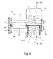
- FIG. 6 a schematic view of the clamping device from above FIG. 5 .
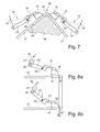
- FIG. 7 a schematic partial section of a clamping position of the clamping modules along the line VI-VI in FIG. 6 .
- FIGS. 8a and 8b a schematic detail of the clamping module for the operation of a solid-state joint of the clamping module according to FIG. 1 .
- FIG. 9 a schematic overview of a sequence of working steps for the exciting picking up of a component
- FIGS. 10a to 10c schematic representations of the individual steps along the section line IX-IX in FIG. 9 .
- FIG. 11 a perspective view of two clamping devices on a work table for simultaneous clamping of two edges of a container
- FIG. 12 a schematic representation of two receiving mandrels of two clamping devices according to FIG. 11 .
- FIG. 13 a schematic plan view in the clamping state of the clamping devices of FIG. 12 .
- FIGS. 14a to 14c schematic views of a clamping device for clamping tubular components
- FIG. 15 a perspective view of a positioning module in a starting position
- FIG. 16 a perspective view of the positioning module according to FIG. 15 in an alignment position
- FIG. 17 a perspective view of the clamping device according to the FIGS. 14a to 14c with the positioning module according to FIG. 17 in the alignment position
- Figures 18a and 18b a schematic sequence of steps for positioning the sheet metal parts to each other with the positioning according to FIG. 15 and
- FIG. 19 a schematic sectional view taken along the line XVIII-XVIII in FIG. 18 .
- FIG. 1 is a perspective view of a clamping module 11 is shown, wherein a front housing portion is removed.
- This clamping module 11 comprises a housing 12 in which a path-generating element 14 is provided, which moves a clamping jaw 18 along a working stroke or clamping stroke according to arrow 19 up and down via a lever mechanism 16.
- the path-generating element 14 is fixedly arranged in the housing 12 or a frame of the housing 12.
- the path-generating element 14 preferably consists of a pneumatic lifting cylinder. Alternatively, a hydraulic lifting cylinder or electromagnetic drive can be provided.
- a connection 33 is provided, to which a supply line, in particular pneumatic line, for the path-generating element 14 can be connected.
- a push rod 21 of the lever mechanism 16 is fixed.
- the pull or push rod 21 is connected to a clamping lever 23, which has an on Housing 12 fixedly mounted pivot axis 25 is rotatably mounted.
- the tensioning lever 23 and the pulling or pushing rod 21 form the lever gear 16.
- a solid-state joint 27 is arranged.
- a releasable clamping element 28 is provided for receiving the solid-state joint 27 in each case on the clamping lever 23 and the clamping jaw 18.
- the solid-state joint 27 can be used interchangeably and adapted to the particular application.
- the solid-state joint 27 is designed according to the first embodiment as a spring bar.
- two parallel with spaced-apart lever mechanism 16 are arranged.
- the path-generating element 14 is arranged to save space. Due to the parallel control of two lever gears 16, a force distribution distributed uniformly over the length of the clamping jaw 18 can take place.
- the clamping module 11 further comprises in the housing 12 in the central region on a positioning opening 31, which is formed for example by four wall sections 32, each adjacent to a front and rear housing wall forming the positioning hole 31, so that the clamping module 11 with respect to the mechanically moving and Closed in the housing 12 components is closed.
- the positioning opening 31 is preferably adapted to the geometry of a clamping bar of a tensioning device described in more detail below.
- a restoring element is further provided by which the lever mechanism 16 is reset from a clamping position to an initial position.
- This may for example be a damping element, spring element or the like.
- the lever mechanism 16 is provided in the housing 12 of the clamping module 11 such that it extends outside the wall sections 32 along the positioning opening 31. At the same time, the necessary lever arms can be made available to save space, the Applying the clamping force are required. It is preferably provided that the lever arm between the pivot axis 25 and the hinge 22 at least twice as long, preferably at least three times as long as the lever arm between the pivot axis 25 and a free end 34 of the pull or push rod 23 is formed. As a result, with a small working stroke of the path-generating element 14, a predefined clamping stroke 19 can be achieved, which is preferably less than 12 mm.
- the clamping jaw 18 is preferably exchangeable and adapted to a welding edge of the component adapted. At the same time, a corresponding choice of material for different clamping jaws 18 can be made.
- the clamping jaw 18 on a clamping surface 41, which preferably extends over the entire surface in the length and width of the clamping jaw 18.
- a tapered clamping edge 42 is formed, which points to a joint or to a weld to be formed.
- An opposite region of the clamping jaw 18 is formed rigid in cross section.
- FIG. 3 is an alternative embodiment to the FIGS. 1 and 2 shown. This embodiment deviates from the embodiment of the solid-state joint 27 of FIG FIGS. 1 and 2 from. Incidentally, reference is made to the above statements.
- the solid-state joint 27 is rod-shaped in this embodiment, wherein adjacent thereto, a fastening portion 36 is provided to fix the solid-body joint 27 on the clamping lever 24 preferably replaceable.
- a fork-shaped receptacle 37 is provided which engages fastening elements 38, in particular screw heads for clamping attachment, on the clamping jaw 18.
- a tapered cross section is formed between the receptacle 37 and the mounting portion 36, which forms the solid-state joint 27.
- rectangular cross-section is formed such that an elastic compliance in and against the clamping stroke is formed according to arrow 19, wherein in a direction perpendicular thereto - ie in Longitudinal axis of the clamping jaw 18 and in the longitudinal axis of the solid-state joint 27 - a high rigidity is given.
- both the receptacle 37 and the solid-state joint 27 are formed by two separate beam sections.
- FIG. 4 a perspective side view of a clamping device 45 according to the invention is shown.
- This clamping device 45 comprises two clamping bars 46, on which the above-described clamping modules 11 can be placed and moved along their longitudinal axis.
- These clamping bars 46 are attached exchangeably to a base plate 47.
- a receiving mandrel 48 is held exchangeably on this base plate 47.
- the two clamping bars 46 and the receiving mandrel 48 are attached on one side to the base plate 47 and arranged in a triangle to each other.
- At the receiving mandrel 48 two components 51 are positioned to each other and kept tense with the clamping modules 11.
- These can be two separate components 51, in particular sheet metal parts, as shown in FIG FIG. 7 is shown or after a forming step already interconnected components 51, the parts of a component, such as a container 50 according to FIG. 5 , represent.
- FIG. 5 shows a perspective view of the clamping device 45 with clamped components 51 of the container 50th
- FIG. 6 shows a schematic view from above FIG. 5 ,
- clamping device 45 two clamping modules 11 are provided on each clamping bar. These are each positioned adjacent to a cantilevered end of the clamping bars 48.
- the clamping modules 11 are arranged in mirror image opposite one another, so that the clamping jaws 18 form a gap 54 ( FIG. 6 ), within which the welding jaws 18 are assigned to one another by the clamping jaws 18, components 51 for forming a joint lie around a linear welding edge with different seam geometries, such as butt joint with I-seam, corner joint or T-joint or I-joint, lap joint or corner seam form.
- the clamping jaws 18 preferably have a length, so that they form a continuous gap 54 when juxtaposing several clamping modules 11 along the clamping bars 46.
- these clamping jaws 18 can serve as a baffle for the inert gas traced by a welding process. This leads to a channeling effect of the protective fumigation, whereby the seam quality is improved by a reduced oxide formation in the seam caterpillar.
- the oxide formation in the seam sub-bead via a protective gas-flowed through groove in the receiving mandrel 48 can also be minimized. This can make the subsequent treatment of the weld surface superfluous to remove an oxide layer.
- a holding device 55 which in each case has an attachment point to the clamping bar 46 and the receiving mandrel 48 to fix them at a predetermined distance from each other.
- This holding device 55 is removable from the clamping bar 46 and the mandrel 48 or pivotally mounted on one of them, so that after the optional application of the clamping modules 11 and optionally the components 51 then followed by a fastening, so that despite the application of a clamping force on the clamping modules 11 the distance between the clamping bar 46 and the receiving mandrel 48 remains constant despite a one-sided clamping of the clamping bar 46 and the receiving mandrel 48.
- uniform clamping conditions for fixing the sheet-metal components 51 are made possible along the longitudinal axis of the receiving mandrel 48, along which the linear welding edge runs.
- the clamping bars 46 and the receiving mandrel 48 are received on the base plate 47 via a centering device 53.
- This centering device 53 enables the clamping bars 46 to be moved relative to the receiving mandrel 48 or vice versa or relative to one another set greater distance to equip the component 51.
- the centering device 53 comprises so-called centering blocks 57, which are fastened to the base plate 47, which engage in one another in a tensioned state. As a result, the occurring clamping forces and resulting bending moments can be securely introduced into the base plate 47 and a higher rigidity can be formed.
- a clamping lever 58 is provided, which from an opening position 59 in accordance with FIG. 4 in a closed position 60 according to FIG. 5 is convertible.
- the centering blocks 57 engage each other.
- it is provided that the receiving mandrel 48 along a guide 61 lowers relative to the clamping jaws 18.
- the arrangement of the clamping bars 46 and the receiving mandrel 48 on the base plate 47 has the advantage that they can be attached to already used in welding modular systems, especially work tables or the like, with a predetermined Lochrasttation.
- FIG. 7 Based on FIG. 7 is a clamping operation of two opposing clamping modules 11 for the assignment of two opposing components 51 to form the joint 56 described in more detail.
- the left member 51 is positioned and held to a bearing surface 62 of the receiving mandrel 48.
- the path generating element 14 is acted upon by compressed air, for example, so that a pivoting movement of the clamping lever 23 in the direction of arrow 63 about the fixed pivot axis 25 is initiated.
- the clamping jaw 18 initially engages with the clamping edge 42 on the component 51. This first clamping state is shown by solid lines.
- a further clamping force is applied via the path-generating element 14, so that the clamping lever 23 is transferred to the dashed position.
- the solid-state joint 27 is deflected elastically yielding, wherein the clamping surface 41 of the clamping jaw 18 conforms to the surface 51 of the component and rests, so that at least one linear, in particular sheet-shaped, plant is given.
- the right-hand component 51 is positioned toward the end face 52 of the component 51 in order to form a joint or the joint 56 for the weld to be subsequently formed.
- the right clamping module 11 is then acted upon analogously with a clamping force.
- both components 51 can be positioned to the mandrel 48 simultaneously and then the left and right clamping module 11 are applied simultaneously or with a time delay.
- the design of the solid-body joint 27, which is elastically yielding in the tensioning direction 19 and mechanically rigid at least in a transverse direction thereto, preferably in both transverse directions, has the advantage that starting from the first tensioning phase according to FIG. 8a for transfer to a final phase according to FIG. 8b If necessary, only a slippage of the component 51 in the direction of the joint 56 can take place, as determined by the distance a in FIG. 8b is shown to prevent the formation of a gap.
- the solid-body joint 27 may alternatively be designed as a leaf spring element or profiled element to the bending bar.
- FIG. 9 and the FIGS. 10a to 10c a schematic sequence of individual steps 1 to 4 for clamping a container 50 is shown, which has at its upper side edges in each case a folded edge 66, which point to the center of the container.
- auxiliary clamping elements 67 can be attached to the receiving mandrel 48, which, for example, have a thickness which corresponds to the width of the folded edge 66.
- the component 51 can be suspended in the receiving mandrel 48, wherein the side wall of the container 50 rests on the auxiliary clamping member 47 and is held under tension with the clamping module 11, so that the end faces of the side walls to form a joint 56 are fixed to each other.
- step 1 of the mandrel 48 by means of the centering device 53 is moved down to the container 50 according to FIG. 10a mount.
- step 2 the receiving mandrel 48 in a clamping position according to FIG. 10b transferred so that in step 3 according to FIG. 10c combined with FIG. 9
- step 4 the left clamping module 11 is also acted upon by a clamping force.
- a weld can be set along the joint 56.
- FIG. 11 is a perspective view of two on a work table 70, in particular on a so-called Demmeler table top, arranged clamping devices 45, which are commonly used in welding technology.
- the arrangement of two clamping devices 45 at a distance from each other, two edges of the container 50, housing or the like can be stretched simultaneously.
- a tensioning device 45 with an adapter element 72 or an adapter plate can be fixed directly on the work table 70, whereas the further tensioning device 45, like this one in FIG FIG. 12 is mounted on a linear module 71 on the work table 70 is attached.
- This linear module 71 preferably has an adjustment path in an axis of the assembly plane of the work table which is smaller than or equal to a perforated grid of the work table 70.
- FIG. 2 shows perspective views of a tensioning device 45, which serves for tensioning components 51 to form tubular components.
- the tensioning device 45 is shown in a loading position.
- the receiving mandrel 48 is adapted in cross-section to the inner contour of the sheet metal parts 51 to be received, or corresponding auxiliary clamping elements 67 are arranged thereon.
- the receiving mandrel 48 to the component 51 facing openings 74 are shown, through which the supply of a protective gas is made possible.
- the holding device 55 is positioned to the receiving mandrel 48 and other clamping bar 46, as shown in FIG FIG.
- positioning modules 81 are preferably provided which can be positioned on the clamping bar 46 and, for example, assigned to a respective end of the component 51 to be applied on the receiving mandrel 48. This goes for example from the Figures 14a and 14c out. Between the positioning modules 81, the clamping modules 11 are arranged. It is sufficient if the positioning modules 81 are arranged on one of the two clamping bars 46.
- FIG. 15 is a perspective view of the positioning module 11 in a starting position 82 and in FIG. 16 shown in an alignment position 83.
- the positioning module 81 comprises a housing 84 which is formed from a front and rear wall section 85, 86. In between, a path-generating element 14 is arranged which actuates a lever mechanism 87.
- This lever mechanism 87 is preferably designed as a toggle lever.
- a pull or push rod 88 is pivotally connected to a pivot lever 89. In a lifting movement of the path generating element 14, the pull or push rod 88 in the X direction according to FIG. 15 at the same time moving a sliding-pivot member 90 in the X direction.
- This sliding-pivot element 90 is movable in a backdrop 92 in the wall section 85, 86 in the X direction back and forth.
- the wall sections 85, 86 comprise a positioning hole 31, which is bordered by at least three end faces on the wall portions 85, 86.
- a clamping element 96 is provided, through which the width of the positioning hole 31 is variable to fix after positioning the Positioniermoduls 81 on the clamping bar 46 by clamping the clamping element 96, the positioning 81 in its position to the clamping bar 46 ,
- FIG. 17 is a schematically enlarged view of the clamping device 45 according to FIG. 14c from which the function of the positioning module 81 emerges and is discussed. In this illustration, the holding device 55 is not shown.
- the positioning modules 81 are transferred from the starting position 82 into the alignment position 83.
- the alignment element 94 is guided along the guide 95.
- the alignment element 94 can engage over the clamping jaws 18 during the feed movement from the starting position 82 into the alignment position 83 so that an end face 97 of the aligning element 94 comes to rest on the receiving mandrel 48 and at the same time a space-saving arrangement of the positioning module 81 is provided for the clamping module 11.
- the clamping jaw 18 is preferably wider than the positioning module 81.
- the component 51 is brought to bear against the two alignment elements 94 of the positioning 81 on the mandrel 48 and then the component 51 associated clamping modules 11 is actuated. After the clamping of the component 51 by the clamping modules 11, the position modules 81 are again transferred to an initial position 82. This transition is for example schematically in the Figures 18a and 18b shown. Subsequently, the further component 51 is positioned for abutment with the first component 51 to form the joint 56, so that subsequently the opposite row of the clamping modules 11 are driven to perform a clamping movement.
- the first component 51 Since the first component 51 is positioned in the correct position over the positioning modules 81 for the receiving mandrel 48, it is necessary for the further component 51 no further positioning via the positioning modules 81, but only for engagement with the first component 51.
- FIG. 19 is a schematic side view of a basic embodiment of the clamping device 45 according to the FIGS. 14a to 14c shown.
- a stop element 98 can be provided on the receiving mandrel 48, which allows a travel limit for the male component 51 in the longitudinal axis of the receiving mandrel 48, ie in the Z direction.
- This stop element 98 can be moved and positioned along the receiving mandrel 48 and, if necessary, can also be removed. As a result, an exact positioning of two opposing components 51 can take place, which do not yet have a connection through another component section.
- a sensory query it is possible via the clamping modules 11, a sensory query whether the or the components 51 are present or the clamping modules 11 have assumed the clamping states. As a result, a higher degree of automation can be achieved.
Landscapes
- Engineering & Computer Science (AREA)
- Physics & Mathematics (AREA)
- Optics & Photonics (AREA)
- Mechanical Engineering (AREA)
- Plasma & Fusion (AREA)
- Laser Beam Processing (AREA)
- Butt Welding And Welding Of Specific Article (AREA)
- Manipulator (AREA)
Applications Claiming Priority (1)
| Application Number | Priority Date | Filing Date | Title |
|---|---|---|---|
| DE102012102820A DE102012102820A1 (de) | 2012-03-30 | 2012-03-30 | Spannmodul und Positioniermodul für eine Spannvorrichtung sowie Spannvorrichtung zum Spannen von Blechbauteilen |
Publications (2)
| Publication Number | Publication Date |
|---|---|
| EP2644314A1 true EP2644314A1 (fr) | 2013-10-02 |
| EP2644314B1 EP2644314B1 (fr) | 2019-03-20 |
Family
ID=48040029
Family Applications (1)
| Application Number | Title | Priority Date | Filing Date |
|---|---|---|---|
| EP13161420.8A Active EP2644314B1 (fr) | 2012-03-30 | 2013-03-27 | Module de serrage pour un dispositif de serrage et dispositif de serrage avec de un tel module et un module de positionnement pour le serrage d'éléments de construction en tôle |
Country Status (4)
| Country | Link |
|---|---|
| US (1) | US20130256965A1 (fr) |
| EP (1) | EP2644314B1 (fr) |
| CN (1) | CN103358070B (fr) |
| DE (1) | DE102012102820A1 (fr) |
Cited By (9)
| Publication number | Priority date | Publication date | Assignee | Title |
|---|---|---|---|---|
| CN107671515A (zh) * | 2017-09-18 | 2018-02-09 | 宁波敏实汽车零部件技术研发有限公司 | 一种分力柔性防拉损汽车外水切胶条装配机构 |
| CN107695653A (zh) * | 2017-09-18 | 2018-02-16 | 宁波敏实汽车零部件技术研发有限公司 | 一种集成胶条柔性装配和端盖组立的外水切组立专用机 |
| CN110125593A (zh) * | 2019-05-31 | 2019-08-16 | 海西华汇化工机械有限公司 | 一种太阳能光热主梁焊接工装平台 |
| CN110586995A (zh) * | 2019-09-23 | 2019-12-20 | 中南林业科技大学 | 一种汽车后扭转梁轮毂连接支架装配面加工装置 |
| CN112108798A (zh) * | 2019-12-31 | 2020-12-22 | 上汽通用五菱汽车股份有限公司 | 汽车抓手总拼系统 |
| CN116571884A (zh) * | 2023-06-30 | 2023-08-11 | 苏州诺克汽车工程装备有限公司 | 用于激光焊接的多方向焊接头及焊接工作站 |
| CN117583814A (zh) * | 2024-01-19 | 2024-02-23 | 格拉默汽车内饰部件(北京)有限公司 | 一种汽车内饰部件生产焊接用定位装置 |
| CN117810137A (zh) * | 2024-03-01 | 2024-04-02 | 深圳市锐铂自动化科技有限公司 | Igbt模块的自动插针机 |
| CN117983966A (zh) * | 2024-04-03 | 2024-05-07 | 四川恒乐达能源工程有限公司 | 一种建筑材料焊接装置 |
Families Citing this family (12)
| Publication number | Priority date | Publication date | Assignee | Title |
|---|---|---|---|---|
| PL2926941T3 (pl) | 2014-04-03 | 2017-08-31 | Bystronic Laser Ag | Urządzenie do obróbki strumieniowej |
| CN108436422A (zh) * | 2018-05-25 | 2018-08-24 | 无锡市光彩机械制造有限公司 | 一种集成型钢模块侧向定位机构 |
| DE102018124313A1 (de) | 2018-10-02 | 2020-04-02 | Trumpf Werkzeugmaschinen Gmbh + Co. Kg | Verfahren und Spannvorrichtung zur Herstellung einer Schweißnaht an einer Stoßstelle zwischen zwei Werkstücken mit einem Laserstrahl |
| CN109648218B (zh) * | 2019-02-21 | 2024-04-09 | 苏州凌创电子系统有限公司 | 传感器引脚自动感测夹持机构 |
| CN109604827B (zh) * | 2019-02-21 | 2024-04-09 | 苏州凌创电子系统有限公司 | 传感器引脚上套筒转动焊接设备 |
| CN110125839B (zh) * | 2019-05-27 | 2020-08-28 | 吉林工程技术师范学院 | 一种汽车铝合金锻造件折叠定位装置 |
| CN110646295B (zh) * | 2019-10-25 | 2022-03-18 | 中铁九局集团工程检测试验有限公司 | 可拆卸式rpc盖板抗裂承载力检测装置 |
| CN111168321B (zh) * | 2020-03-05 | 2021-08-31 | 黑龙江建筑职业技术学院 | 一种用于暖通管焊接的固定夹具 |
| CN112620934A (zh) * | 2020-12-11 | 2021-04-09 | 付军平 | 一种激光束加工设备 |
| CN113257442B (zh) * | 2021-05-12 | 2024-11-19 | 上海核工程研究设计院股份有限公司 | 一种基于同步液压装置的夹持型支座 |
| CN113478407B (zh) * | 2021-06-02 | 2022-09-27 | 机械工业第九设计研究院股份有限公司 | 一种带有弹力张紧的精确夹紧定位机构 |
| DE102024105699A1 (de) * | 2024-02-28 | 2025-08-28 | Fraunhofer-Gesellschaft zur Förderung der angewandten Forschung eingetragener Verein | Verfahren, Formteil und Fügeanordnung zum Fügen von mindestens zwei Bauteilen |
Citations (10)
| Publication number | Priority date | Publication date | Assignee | Title |
|---|---|---|---|---|
| US3988865A (en) * | 1973-03-02 | 1976-11-02 | Charles Weisman | Clamp and jig for use therewith |
| SU893485A1 (ru) * | 1980-03-21 | 1981-12-30 | Предприятие П/Я Г-4086 | Механизм дл прижима листовых изделий под сварку |
| JPH04127996A (ja) * | 1990-09-18 | 1992-04-28 | Amada Co Ltd | 溶接機の被溶接物クランプ装置 |
| FR2677570A1 (fr) * | 1991-06-13 | 1992-12-18 | Badart Jacques | Dispositif de serrage d'un corps par rapport a un referentiel. |
| US5674420A (en) * | 1995-06-12 | 1997-10-07 | Worthington Industries Incorporated | Clamping device for welding machine |
| JP2001287090A (ja) * | 2000-04-10 | 2001-10-16 | Mitsubishi Heavy Ind Ltd | 突合せ溶接における基準位置決め機構 |
| JP2001328042A (ja) * | 2000-05-24 | 2001-11-27 | Sanyo Mach Works Ltd | クランプ装置 |
| DE10029293A1 (de) | 2000-06-14 | 2002-01-03 | Daimler Chrysler Ag | Vorrichtung und Verfahren zum Laserstrahlschweißen von Blechplatinen |
| DE102006035517B3 (de) | 2006-07-31 | 2007-09-13 | Audi Ag | Spanneinrichtung zum Spannen von Blechplatinen in einer Schweißvorrichtung |
| DE202007017274U1 (de) * | 2007-12-11 | 2008-03-06 | Tünkers Maschinenbau Gmbh | Vorrichtung zum Positionieren und/oder Zentrieren von blechförmigen Körpern oder Tafeln, insbesondere von Karosserieteilen im Kfz-Bau |
Family Cites Families (6)
| Publication number | Priority date | Publication date | Assignee | Title |
|---|---|---|---|---|
| US5893449A (en) * | 1997-05-08 | 1999-04-13 | Owens-Brockway Glass Container Inc. | Lehr loader |
| CN2803609Y (zh) * | 2005-04-29 | 2006-08-09 | 罗琳 | 一种工件移动夹紧装置 |
| US8596622B2 (en) * | 2009-10-16 | 2013-12-03 | Laitram, L.L.C. | Rapid-release belt splicer and method of operation |
| CN101733603A (zh) * | 2009-12-07 | 2010-06-16 | 昆山华恒工程技术中心有限公司 | 柔性琴键夹具 |
| CN102179779A (zh) * | 2010-12-28 | 2011-09-14 | 苏州新区科兴威尔电子有限公司 | 一种夹紧机构 |
| CN202155680U (zh) * | 2011-07-15 | 2012-03-07 | 铜陵伟达机械制造有限公司 | 一种夹紧定位装置 |
-
2012
- 2012-03-30 DE DE102012102820A patent/DE102012102820A1/de not_active Withdrawn
-
2013
- 2013-03-27 EP EP13161420.8A patent/EP2644314B1/fr active Active
- 2013-04-01 CN CN201310110517.1A patent/CN103358070B/zh active Active
- 2013-04-01 US US13/854,468 patent/US20130256965A1/en not_active Abandoned
Patent Citations (10)
| Publication number | Priority date | Publication date | Assignee | Title |
|---|---|---|---|---|
| US3988865A (en) * | 1973-03-02 | 1976-11-02 | Charles Weisman | Clamp and jig for use therewith |
| SU893485A1 (ru) * | 1980-03-21 | 1981-12-30 | Предприятие П/Я Г-4086 | Механизм дл прижима листовых изделий под сварку |
| JPH04127996A (ja) * | 1990-09-18 | 1992-04-28 | Amada Co Ltd | 溶接機の被溶接物クランプ装置 |
| FR2677570A1 (fr) * | 1991-06-13 | 1992-12-18 | Badart Jacques | Dispositif de serrage d'un corps par rapport a un referentiel. |
| US5674420A (en) * | 1995-06-12 | 1997-10-07 | Worthington Industries Incorporated | Clamping device for welding machine |
| JP2001287090A (ja) * | 2000-04-10 | 2001-10-16 | Mitsubishi Heavy Ind Ltd | 突合せ溶接における基準位置決め機構 |
| JP2001328042A (ja) * | 2000-05-24 | 2001-11-27 | Sanyo Mach Works Ltd | クランプ装置 |
| DE10029293A1 (de) | 2000-06-14 | 2002-01-03 | Daimler Chrysler Ag | Vorrichtung und Verfahren zum Laserstrahlschweißen von Blechplatinen |
| DE102006035517B3 (de) | 2006-07-31 | 2007-09-13 | Audi Ag | Spanneinrichtung zum Spannen von Blechplatinen in einer Schweißvorrichtung |
| DE202007017274U1 (de) * | 2007-12-11 | 2008-03-06 | Tünkers Maschinenbau Gmbh | Vorrichtung zum Positionieren und/oder Zentrieren von blechförmigen Körpern oder Tafeln, insbesondere von Karosserieteilen im Kfz-Bau |
Non-Patent Citations (1)
| Title |
|---|
| DATABASE WPI Week 198244, Derwent World Patents Index; AN 1982-94454E, XP002706406 * |
Cited By (14)
| Publication number | Priority date | Publication date | Assignee | Title |
|---|---|---|---|---|
| CN107671515B (zh) * | 2017-09-18 | 2024-03-26 | 宁波敏实汽车零部件技术研发有限公司 | 一种分力柔性防拉损汽车外水切胶条装配机构 |
| CN107695653A (zh) * | 2017-09-18 | 2018-02-16 | 宁波敏实汽车零部件技术研发有限公司 | 一种集成胶条柔性装配和端盖组立的外水切组立专用机 |
| CN107671515A (zh) * | 2017-09-18 | 2018-02-09 | 宁波敏实汽车零部件技术研发有限公司 | 一种分力柔性防拉损汽车外水切胶条装配机构 |
| CN107695653B (zh) * | 2017-09-18 | 2024-03-26 | 宁波敏实汽车零部件技术研发有限公司 | 一种集成胶条柔性装配和端盖组立的外水切组立专用机 |
| CN110125593A (zh) * | 2019-05-31 | 2019-08-16 | 海西华汇化工机械有限公司 | 一种太阳能光热主梁焊接工装平台 |
| CN110586995A (zh) * | 2019-09-23 | 2019-12-20 | 中南林业科技大学 | 一种汽车后扭转梁轮毂连接支架装配面加工装置 |
| CN110586995B (zh) * | 2019-09-23 | 2020-08-07 | 中南林业科技大学 | 一种汽车后扭转梁轮毂连接支架装配面加工装置 |
| CN112108798A (zh) * | 2019-12-31 | 2020-12-22 | 上汽通用五菱汽车股份有限公司 | 汽车抓手总拼系统 |
| CN116571884A (zh) * | 2023-06-30 | 2023-08-11 | 苏州诺克汽车工程装备有限公司 | 用于激光焊接的多方向焊接头及焊接工作站 |
| CN117583814A (zh) * | 2024-01-19 | 2024-02-23 | 格拉默汽车内饰部件(北京)有限公司 | 一种汽车内饰部件生产焊接用定位装置 |
| CN117810137A (zh) * | 2024-03-01 | 2024-04-02 | 深圳市锐铂自动化科技有限公司 | Igbt模块的自动插针机 |
| CN117810137B (zh) * | 2024-03-01 | 2024-04-26 | 深圳市锐铂自动化科技有限公司 | Igbt模块的自动插针机 |
| CN117983966A (zh) * | 2024-04-03 | 2024-05-07 | 四川恒乐达能源工程有限公司 | 一种建筑材料焊接装置 |
| CN117983966B (zh) * | 2024-04-03 | 2024-06-04 | 四川恒乐达能源工程有限公司 | 一种建筑材料焊接装置 |
Also Published As
| Publication number | Publication date |
|---|---|
| US20130256965A1 (en) | 2013-10-03 |
| EP2644314B1 (fr) | 2019-03-20 |
| CN103358070B (zh) | 2016-12-28 |
| DE102012102820A1 (de) | 2013-10-02 |
| CN103358070A (zh) | 2013-10-23 |
Similar Documents
| Publication | Publication Date | Title |
|---|---|---|
| EP2644314B1 (fr) | Module de serrage pour un dispositif de serrage et dispositif de serrage avec de un tel module et un module de positionnement pour le serrage d'éléments de construction en tôle | |
| DE2839978C2 (fr) | ||
| EP2834022B1 (fr) | Dispositif et procédé de fabrication de profilés ou d'éléments tubulaires au moins en partie fermés à partir de tôle métallique | |
| DE19836374C1 (de) | Verfahren und Vorrichtung zum Fügen eines Laschenkettengliedes | |
| WO2019141714A1 (fr) | Cintreuse et procédé de cintrage d'une pièce composée d'un matériau plat | |
| EP3515619B1 (fr) | Outil, machine-outil et procédé d'usinage de pièces en forme de plaque | |
| EP3299094A1 (fr) | Procédé de fabrication d'une pièce à usiner et outil de découpe/manipulation destiné à exécuter le procédé | |
| EP2481492B1 (fr) | Outil de pliage pour le pliage à forme libre de tôles | |
| WO2022128535A1 (fr) | Dispositif de remplacement et procédé de remplacement pour une pièce en forme de plaque dans une machine d'usinage | |
| EP3755480B1 (fr) | Installation de fabrication comprenant une unité de changement d'outil et une mâchoire de serrage, ainsi que procédé de changement d'outil | |
| EP2029314A1 (fr) | Porte-pièce destiné à recevoir une pièce en particulier en forme de plaque dans une unité d'usinage comprenant des éléments de support mobiles présentant des pointes d'appui | |
| CH680992A5 (fr) | ||
| EP3551356B1 (fr) | Installation de fabrication dotée d'un outil de serrage ainsi que procédé de réglage d'une longueur totale d'un bord de pliage de l'outil de serrage | |
| EP3515617B1 (fr) | Outil et machine-outil ainsi que procédé d'usinage de pièces en forme de plaque | |
| DE102004052951B4 (de) | Spannvorrichtung | |
| AT518648A4 (de) | Streckbiegemaschine und Verfahren zum Verformen eines Werkstückes | |
| DE10029293B4 (de) | Vorrichtung und Verfahren zum Laserstrahlschweißen von Blechplatinen | |
| AT518255B1 (de) | Werkzeugwechselvorrichtung für eine Abkantpresse und Verfahren zum Durchführen eines Werkzeugwechsels | |
| WO2007134630A1 (fr) | Procédé, dispositif de réglage et élément de support pour régler un porte-pièce destiné à recevoir une pièce en forme de plaque | |
| DE2733252C3 (de) | Verfahren und Vorrichtung zum Herstellen eines Gitterträgers | |
| EP2845663B1 (fr) | Presse plieuse avec un outil de cintrage composé de plusieurs éléments d'outil | |
| DE3025375A1 (de) | Verfahren zum schweissen von metallstangen | |
| EP3061553A1 (fr) | Dispositif de traitement de pieces a bord coupant comprenant un dispositif de serrage | |
| DE102019129967A1 (de) | Verfahren zur Verbindung von Teilen im Bereich einer unregelmäßig verlaufenden Konturlinie und Werkzeug | |
| EP1674195B1 (fr) | Procédé de fabrication d'une liaison soudée entre deux profils creux insérés l'un dans l'autre employant un dispositif de pression pour supprimer le jeu avant l'étape de soudage : dispositif de pression correspondant |
Legal Events
| Date | Code | Title | Description |
|---|---|---|---|
| PUAI | Public reference made under article 153(3) epc to a published international application that has entered the european phase |
Free format text: ORIGINAL CODE: 0009012 |
|
| AK | Designated contracting states |
Kind code of ref document: A1 Designated state(s): AL AT BE BG CH CY CZ DE DK EE ES FI FR GB GR HR HU IE IS IT LI LT LU LV MC MK MT NL NO PL PT RO RS SE SI SK SM TR |
|
| AX | Request for extension of the european patent |
Extension state: BA ME |
|
| 17P | Request for examination filed |
Effective date: 20140402 |
|
| RBV | Designated contracting states (corrected) |
Designated state(s): AL AT BE BG CH CY CZ DE DK EE ES FI FR GB GR HR HU IE IS IT LI LT LU LV MC MK MT NL NO PL PT RO RS SE SI SK SM TR |
|
| 17Q | First examination report despatched |
Effective date: 20141029 |
|
| GRAP | Despatch of communication of intention to grant a patent |
Free format text: ORIGINAL CODE: EPIDOSNIGR1 |
|
| STAA | Information on the status of an ep patent application or granted ep patent |
Free format text: STATUS: GRANT OF PATENT IS INTENDED |
|
| INTG | Intention to grant announced |
Effective date: 20181121 |
|
| GRAS | Grant fee paid |
Free format text: ORIGINAL CODE: EPIDOSNIGR3 |
|
| GRAA | (expected) grant |
Free format text: ORIGINAL CODE: 0009210 |
|
| STAA | Information on the status of an ep patent application or granted ep patent |
Free format text: STATUS: THE PATENT HAS BEEN GRANTED |
|
| AK | Designated contracting states |
Kind code of ref document: B1 Designated state(s): AL AT BE BG CH CY CZ DE DK EE ES FI FR GB GR HR HU IE IS IT LI LT LU LV MC MK MT NL NO PL PT RO RS SE SI SK SM TR |
|
| REG | Reference to a national code |
Ref country code: GB Ref legal event code: FG4D Free format text: NOT ENGLISH |
|
| REG | Reference to a national code |
Ref country code: CH Ref legal event code: EP |
|
| REG | Reference to a national code |
Ref country code: DE Ref legal event code: R096 Ref document number: 502013012436 Country of ref document: DE |
|
| REG | Reference to a national code |
Ref country code: AT Ref legal event code: REF Ref document number: 1110048 Country of ref document: AT Kind code of ref document: T Effective date: 20190415 |
|
| REG | Reference to a national code |
Ref country code: IE Ref legal event code: FG4D Free format text: LANGUAGE OF EP DOCUMENT: GERMAN |
|
| REG | Reference to a national code |
Ref country code: CH Ref legal event code: NV Representative=s name: DENNEMEYER AG, CH |
|
| REG | Reference to a national code |
Ref country code: NL Ref legal event code: MP Effective date: 20190320 |
|
| PG25 | Lapsed in a contracting state [announced via postgrant information from national office to epo] |
Ref country code: NO Free format text: LAPSE BECAUSE OF FAILURE TO SUBMIT A TRANSLATION OF THE DESCRIPTION OR TO PAY THE FEE WITHIN THE PRESCRIBED TIME-LIMIT Effective date: 20190620 Ref country code: FI Free format text: LAPSE BECAUSE OF FAILURE TO SUBMIT A TRANSLATION OF THE DESCRIPTION OR TO PAY THE FEE WITHIN THE PRESCRIBED TIME-LIMIT Effective date: 20190320 Ref country code: LT Free format text: LAPSE BECAUSE OF FAILURE TO SUBMIT A TRANSLATION OF THE DESCRIPTION OR TO PAY THE FEE WITHIN THE PRESCRIBED TIME-LIMIT Effective date: 20190320 Ref country code: SE Free format text: LAPSE BECAUSE OF FAILURE TO SUBMIT A TRANSLATION OF THE DESCRIPTION OR TO PAY THE FEE WITHIN THE PRESCRIBED TIME-LIMIT Effective date: 20190320 |
|
| REG | Reference to a national code |
Ref country code: LT Ref legal event code: MG4D |
|
| PG25 | Lapsed in a contracting state [announced via postgrant information from national office to epo] |
Ref country code: NL Free format text: LAPSE BECAUSE OF FAILURE TO SUBMIT A TRANSLATION OF THE DESCRIPTION OR TO PAY THE FEE WITHIN THE PRESCRIBED TIME-LIMIT Effective date: 20190320 Ref country code: BG Free format text: LAPSE BECAUSE OF FAILURE TO SUBMIT A TRANSLATION OF THE DESCRIPTION OR TO PAY THE FEE WITHIN THE PRESCRIBED TIME-LIMIT Effective date: 20190620 Ref country code: GR Free format text: LAPSE BECAUSE OF FAILURE TO SUBMIT A TRANSLATION OF THE DESCRIPTION OR TO PAY THE FEE WITHIN THE PRESCRIBED TIME-LIMIT Effective date: 20190621 Ref country code: RS Free format text: LAPSE BECAUSE OF FAILURE TO SUBMIT A TRANSLATION OF THE DESCRIPTION OR TO PAY THE FEE WITHIN THE PRESCRIBED TIME-LIMIT Effective date: 20190320 Ref country code: HR Free format text: LAPSE BECAUSE OF FAILURE TO SUBMIT A TRANSLATION OF THE DESCRIPTION OR TO PAY THE FEE WITHIN THE PRESCRIBED TIME-LIMIT Effective date: 20190320 Ref country code: LV Free format text: LAPSE BECAUSE OF FAILURE TO SUBMIT A TRANSLATION OF THE DESCRIPTION OR TO PAY THE FEE WITHIN THE PRESCRIBED TIME-LIMIT Effective date: 20190320 |
|
| PG25 | Lapsed in a contracting state [announced via postgrant information from national office to epo] |
Ref country code: PT Free format text: LAPSE BECAUSE OF FAILURE TO SUBMIT A TRANSLATION OF THE DESCRIPTION OR TO PAY THE FEE WITHIN THE PRESCRIBED TIME-LIMIT Effective date: 20190720 Ref country code: AL Free format text: LAPSE BECAUSE OF FAILURE TO SUBMIT A TRANSLATION OF THE DESCRIPTION OR TO PAY THE FEE WITHIN THE PRESCRIBED TIME-LIMIT Effective date: 20190320 Ref country code: EE Free format text: LAPSE BECAUSE OF FAILURE TO SUBMIT A TRANSLATION OF THE DESCRIPTION OR TO PAY THE FEE WITHIN THE PRESCRIBED TIME-LIMIT Effective date: 20190320 Ref country code: IT Free format text: LAPSE BECAUSE OF FAILURE TO SUBMIT A TRANSLATION OF THE DESCRIPTION OR TO PAY THE FEE WITHIN THE PRESCRIBED TIME-LIMIT Effective date: 20190320 Ref country code: RO Free format text: LAPSE BECAUSE OF FAILURE TO SUBMIT A TRANSLATION OF THE DESCRIPTION OR TO PAY THE FEE WITHIN THE PRESCRIBED TIME-LIMIT Effective date: 20190320 Ref country code: CZ Free format text: LAPSE BECAUSE OF FAILURE TO SUBMIT A TRANSLATION OF THE DESCRIPTION OR TO PAY THE FEE WITHIN THE PRESCRIBED TIME-LIMIT Effective date: 20190320 Ref country code: SK Free format text: LAPSE BECAUSE OF FAILURE TO SUBMIT A TRANSLATION OF THE DESCRIPTION OR TO PAY THE FEE WITHIN THE PRESCRIBED TIME-LIMIT Effective date: 20190320 Ref country code: ES Free format text: LAPSE BECAUSE OF FAILURE TO SUBMIT A TRANSLATION OF THE DESCRIPTION OR TO PAY THE FEE WITHIN THE PRESCRIBED TIME-LIMIT Effective date: 20190320 |
|
| PG25 | Lapsed in a contracting state [announced via postgrant information from national office to epo] |
Ref country code: SM Free format text: LAPSE BECAUSE OF FAILURE TO SUBMIT A TRANSLATION OF THE DESCRIPTION OR TO PAY THE FEE WITHIN THE PRESCRIBED TIME-LIMIT Effective date: 20190320 Ref country code: PL Free format text: LAPSE BECAUSE OF FAILURE TO SUBMIT A TRANSLATION OF THE DESCRIPTION OR TO PAY THE FEE WITHIN THE PRESCRIBED TIME-LIMIT Effective date: 20190320 Ref country code: LU Free format text: LAPSE BECAUSE OF NON-PAYMENT OF DUE FEES Effective date: 20190327 |
|
| REG | Reference to a national code |
Ref country code: BE Ref legal event code: MM Effective date: 20190331 |
|
| PG25 | Lapsed in a contracting state [announced via postgrant information from national office to epo] |
Ref country code: IS Free format text: LAPSE BECAUSE OF FAILURE TO SUBMIT A TRANSLATION OF THE DESCRIPTION OR TO PAY THE FEE WITHIN THE PRESCRIBED TIME-LIMIT Effective date: 20190720 |
|
| REG | Reference to a national code |
Ref country code: DE Ref legal event code: R097 Ref document number: 502013012436 Country of ref document: DE |
|
| PLBE | No opposition filed within time limit |
Free format text: ORIGINAL CODE: 0009261 |
|
| STAA | Information on the status of an ep patent application or granted ep patent |
Free format text: STATUS: NO OPPOSITION FILED WITHIN TIME LIMIT |
|
| PG25 | Lapsed in a contracting state [announced via postgrant information from national office to epo] |
Ref country code: DK Free format text: LAPSE BECAUSE OF FAILURE TO SUBMIT A TRANSLATION OF THE DESCRIPTION OR TO PAY THE FEE WITHIN THE PRESCRIBED TIME-LIMIT Effective date: 20190320 Ref country code: IE Free format text: LAPSE BECAUSE OF NON-PAYMENT OF DUE FEES Effective date: 20190327 Ref country code: MC Free format text: LAPSE BECAUSE OF FAILURE TO SUBMIT A TRANSLATION OF THE DESCRIPTION OR TO PAY THE FEE WITHIN THE PRESCRIBED TIME-LIMIT Effective date: 20190320 |
|
| 26N | No opposition filed |
Effective date: 20200102 |
|
| GBPC | Gb: european patent ceased through non-payment of renewal fee |
Effective date: 20190620 |
|
| PG25 | Lapsed in a contracting state [announced via postgrant information from national office to epo] |
Ref country code: BE Free format text: LAPSE BECAUSE OF NON-PAYMENT OF DUE FEES Effective date: 20190331 Ref country code: SI Free format text: LAPSE BECAUSE OF FAILURE TO SUBMIT A TRANSLATION OF THE DESCRIPTION OR TO PAY THE FEE WITHIN THE PRESCRIBED TIME-LIMIT Effective date: 20190320 |
|
| PG25 | Lapsed in a contracting state [announced via postgrant information from national office to epo] |
Ref country code: TR Free format text: LAPSE BECAUSE OF FAILURE TO SUBMIT A TRANSLATION OF THE DESCRIPTION OR TO PAY THE FEE WITHIN THE PRESCRIBED TIME-LIMIT Effective date: 20190320 |
|
| PG25 | Lapsed in a contracting state [announced via postgrant information from national office to epo] |
Ref country code: GB Free format text: LAPSE BECAUSE OF NON-PAYMENT OF DUE FEES Effective date: 20190620 |
|
| PG25 | Lapsed in a contracting state [announced via postgrant information from national office to epo] |
Ref country code: FR Free format text: LAPSE BECAUSE OF NON-PAYMENT OF DUE FEES Effective date: 20190520 Ref country code: MT Free format text: LAPSE BECAUSE OF FAILURE TO SUBMIT A TRANSLATION OF THE DESCRIPTION OR TO PAY THE FEE WITHIN THE PRESCRIBED TIME-LIMIT Effective date: 20190320 |
|
| PG25 | Lapsed in a contracting state [announced via postgrant information from national office to epo] |
Ref country code: CY Free format text: LAPSE BECAUSE OF FAILURE TO SUBMIT A TRANSLATION OF THE DESCRIPTION OR TO PAY THE FEE WITHIN THE PRESCRIBED TIME-LIMIT Effective date: 20190320 |
|
| PG25 | Lapsed in a contracting state [announced via postgrant information from national office to epo] |
Ref country code: HU Free format text: LAPSE BECAUSE OF FAILURE TO SUBMIT A TRANSLATION OF THE DESCRIPTION OR TO PAY THE FEE WITHIN THE PRESCRIBED TIME-LIMIT; INVALID AB INITIO Effective date: 20130327 |
|
| PGFP | Annual fee paid to national office [announced via postgrant information from national office to epo] |
Ref country code: AT Payment date: 20220322 Year of fee payment: 10 |
|
| PG25 | Lapsed in a contracting state [announced via postgrant information from national office to epo] |
Ref country code: MK Free format text: LAPSE BECAUSE OF FAILURE TO SUBMIT A TRANSLATION OF THE DESCRIPTION OR TO PAY THE FEE WITHIN THE PRESCRIBED TIME-LIMIT Effective date: 20190320 |
|
| PGFP | Annual fee paid to national office [announced via postgrant information from national office to epo] |
Ref country code: CH Payment date: 20230401 Year of fee payment: 11 |
|
| REG | Reference to a national code |
Ref country code: AT Ref legal event code: MM01 Ref document number: 1110048 Country of ref document: AT Kind code of ref document: T Effective date: 20230327 |
|
| PG25 | Lapsed in a contracting state [announced via postgrant information from national office to epo] |
Ref country code: AT Free format text: LAPSE BECAUSE OF NON-PAYMENT OF DUE FEES Effective date: 20230327 |
|
| REG | Reference to a national code |
Ref country code: DE Ref legal event code: R081 Ref document number: 502013012436 Country of ref document: DE Owner name: TRUMPF LASER- UND SYSTEMTECHNIK SE, DE Free format text: FORMER OWNER: TRUMPF LASER- UND SYSTEMTECHNIK GMBH, 71254 DITZINGEN, DE |
|
| REG | Reference to a national code |
Ref country code: CH Ref legal event code: PL |
|
| PG25 | Lapsed in a contracting state [announced via postgrant information from national office to epo] |
Ref country code: CH Free format text: LAPSE BECAUSE OF NON-PAYMENT OF DUE FEES Effective date: 20240331 |
|
| PGFP | Annual fee paid to national office [announced via postgrant information from national office to epo] |
Ref country code: DE Payment date: 20260320 Year of fee payment: 14 |