EP2644414B1 - Véhicule électrique - Google Patents
Véhicule électrique Download PDFInfo
- Publication number
- EP2644414B1 EP2644414B1 EP13157550.8A EP13157550A EP2644414B1 EP 2644414 B1 EP2644414 B1 EP 2644414B1 EP 13157550 A EP13157550 A EP 13157550A EP 2644414 B1 EP2644414 B1 EP 2644414B1
- Authority
- EP
- European Patent Office
- Prior art keywords
- case
- wheel
- motor
- upper arm
- vehicle
- Prior art date
- Legal status (The legal status is an assumption and is not a legal conclusion. Google has not performed a legal analysis and makes no representation as to the accuracy of the status listed.)
- Not-in-force
Links
- 239000003638 chemical reducing agent Substances 0.000 claims description 31
- 230000002093 peripheral effect Effects 0.000 claims description 6
- 230000001419 dependent effect Effects 0.000 claims 1
- 239000000725 suspension Substances 0.000 description 11
- 230000033001 locomotion Effects 0.000 description 4
- 238000000034 method Methods 0.000 description 3
- 239000006096 absorbing agent Substances 0.000 description 2
- 238000000926 separation method Methods 0.000 description 2
- 230000035939 shock Effects 0.000 description 2
- 238000005452 bending Methods 0.000 description 1
- 230000005540 biological transmission Effects 0.000 description 1
- 239000000872 buffer Substances 0.000 description 1
- 238000006073 displacement reaction Methods 0.000 description 1
- 230000000694 effects Effects 0.000 description 1
- 230000007613 environmental effect Effects 0.000 description 1
- 230000000149 penetrating effect Effects 0.000 description 1
- 238000005096 rolling process Methods 0.000 description 1
Images





Classifications
-
- B—PERFORMING OPERATIONS; TRANSPORTING
- B60—VEHICLES IN GENERAL
- B60K—ARRANGEMENT OR MOUNTING OF PROPULSION UNITS OR OF TRANSMISSIONS IN VEHICLES; ARRANGEMENT OR MOUNTING OF PLURAL DIVERSE PRIME-MOVERS IN VEHICLES; AUXILIARY DRIVES FOR VEHICLES; INSTRUMENTATION OR DASHBOARDS FOR VEHICLES; ARRANGEMENTS IN CONNECTION WITH COOLING, AIR INTAKE, GAS EXHAUST OR FUEL SUPPLY OF PROPULSION UNITS IN VEHICLES
- B60K7/00—Disposition of motor in, or adjacent to, traction wheel
- B60K7/0007—Disposition of motor in, or adjacent to, traction wheel the motor being electric
-
- B—PERFORMING OPERATIONS; TRANSPORTING
- B60—VEHICLES IN GENERAL
- B60G—VEHICLE SUSPENSION ARRANGEMENTS
- B60G3/00—Resilient suspensions for a single wheel
- B60G3/18—Resilient suspensions for a single wheel with two or more pivoted arms, e.g. parallelogram
- B60G3/20—Resilient suspensions for a single wheel with two or more pivoted arms, e.g. parallelogram all arms being rigid
-
- B—PERFORMING OPERATIONS; TRANSPORTING
- B60—VEHICLES IN GENERAL
- B60K—ARRANGEMENT OR MOUNTING OF PROPULSION UNITS OR OF TRANSMISSIONS IN VEHICLES; ARRANGEMENT OR MOUNTING OF PLURAL DIVERSE PRIME-MOVERS IN VEHICLES; AUXILIARY DRIVES FOR VEHICLES; INSTRUMENTATION OR DASHBOARDS FOR VEHICLES; ARRANGEMENTS IN CONNECTION WITH COOLING, AIR INTAKE, GAS EXHAUST OR FUEL SUPPLY OF PROPULSION UNITS IN VEHICLES
- B60K1/00—Arrangement or mounting of electrical propulsion units
- B60K1/04—Arrangement or mounting of electrical propulsion units of the electric storage means for propulsion
-
- B—PERFORMING OPERATIONS; TRANSPORTING
- B60—VEHICLES IN GENERAL
- B60K—ARRANGEMENT OR MOUNTING OF PROPULSION UNITS OR OF TRANSMISSIONS IN VEHICLES; ARRANGEMENT OR MOUNTING OF PLURAL DIVERSE PRIME-MOVERS IN VEHICLES; AUXILIARY DRIVES FOR VEHICLES; INSTRUMENTATION OR DASHBOARDS FOR VEHICLES; ARRANGEMENTS IN CONNECTION WITH COOLING, AIR INTAKE, GAS EXHAUST OR FUEL SUPPLY OF PROPULSION UNITS IN VEHICLES
- B60K17/00—Arrangement or mounting of transmissions in vehicles
- B60K17/04—Arrangement or mounting of transmissions in vehicles characterised by arrangement, location or kind of gearing
- B60K17/043—Transmission unit disposed in on near the vehicle wheel, or between the differential gear unit and the wheel
-
- B—PERFORMING OPERATIONS; TRANSPORTING
- B60—VEHICLES IN GENERAL
- B60G—VEHICLE SUSPENSION ARRANGEMENTS
- B60G2204/00—Indexing codes related to suspensions per se or to auxiliary parts
- B60G2204/10—Mounting of suspension elements
- B60G2204/14—Mounting of suspension arms
-
- B—PERFORMING OPERATIONS; TRANSPORTING
- B60—VEHICLES IN GENERAL
- B60G—VEHICLE SUSPENSION ARRANGEMENTS
- B60G2204/00—Indexing codes related to suspensions per se or to auxiliary parts
- B60G2204/10—Mounting of suspension elements
- B60G2204/18—Mounting of vehicle engines
- B60G2204/182—Electric motor on wheel support
-
- B—PERFORMING OPERATIONS; TRANSPORTING
- B60—VEHICLES IN GENERAL
- B60K—ARRANGEMENT OR MOUNTING OF PROPULSION UNITS OR OF TRANSMISSIONS IN VEHICLES; ARRANGEMENT OR MOUNTING OF PLURAL DIVERSE PRIME-MOVERS IN VEHICLES; AUXILIARY DRIVES FOR VEHICLES; INSTRUMENTATION OR DASHBOARDS FOR VEHICLES; ARRANGEMENTS IN CONNECTION WITH COOLING, AIR INTAKE, GAS EXHAUST OR FUEL SUPPLY OF PROPULSION UNITS IN VEHICLES
- B60K1/00—Arrangement or mounting of electrical propulsion units
- B60K1/04—Arrangement or mounting of electrical propulsion units of the electric storage means for propulsion
- B60K2001/0405—Arrangement or mounting of electrical propulsion units of the electric storage means for propulsion characterised by their position
- B60K2001/0438—Arrangement under the floor
-
- B—PERFORMING OPERATIONS; TRANSPORTING
- B60—VEHICLES IN GENERAL
- B60K—ARRANGEMENT OR MOUNTING OF PROPULSION UNITS OR OF TRANSMISSIONS IN VEHICLES; ARRANGEMENT OR MOUNTING OF PLURAL DIVERSE PRIME-MOVERS IN VEHICLES; AUXILIARY DRIVES FOR VEHICLES; INSTRUMENTATION OR DASHBOARDS FOR VEHICLES; ARRANGEMENTS IN CONNECTION WITH COOLING, AIR INTAKE, GAS EXHAUST OR FUEL SUPPLY OF PROPULSION UNITS IN VEHICLES
- B60K7/00—Disposition of motor in, or adjacent to, traction wheel
- B60K2007/0038—Disposition of motor in, or adjacent to, traction wheel the motor moving together with the wheel axle
-
- B—PERFORMING OPERATIONS; TRANSPORTING
- B60—VEHICLES IN GENERAL
- B60K—ARRANGEMENT OR MOUNTING OF PROPULSION UNITS OR OF TRANSMISSIONS IN VEHICLES; ARRANGEMENT OR MOUNTING OF PLURAL DIVERSE PRIME-MOVERS IN VEHICLES; AUXILIARY DRIVES FOR VEHICLES; INSTRUMENTATION OR DASHBOARDS FOR VEHICLES; ARRANGEMENTS IN CONNECTION WITH COOLING, AIR INTAKE, GAS EXHAUST OR FUEL SUPPLY OF PROPULSION UNITS IN VEHICLES
- B60K7/00—Disposition of motor in, or adjacent to, traction wheel
- B60K2007/0061—Disposition of motor in, or adjacent to, traction wheel the motor axle being parallel to the wheel axle
Definitions
- the present invention relates to an electric vehicle in which left and right drive wheels are driven respectively by electric drive units.
- Electric vehicles which can achieve energy saving and reduction in environmental load are attracting attention and are being put to practical use.
- a drive method in which one electric motor drives one drive wheel see Japanese Patent Application Publication No. 2006-248417 , and in particular Fig. 1 , for example.
- Other examples are shown in EP 1950072 and EP 0525663 , and FR 2776966 (on which the preamble of claim 1 is based) discloses an arrangement where a plurality of motors are arranged to drive a single driven wheel.
- motors an electric motor, a hydraulic motor, and a pneumatic motor are collectively referred to as "motors”.
- motors When it is necessary to specify the type of the motor, the term “electric motor” is used.
- a drive wheel (10) is driven by an in-wheel motor (20) (the numbers in parentheses indicates the reference numerals used in Japanese Patent Application Publication No. 2006-248417 ).
- the in-wheel motor (20) is an electric motor unit with a reducer in which a gear reducer is integrated with an electric motor, and is disposed in a bowl-shaped recessed portion of a wheel (13).
- the drive wheel (10) is suspended from a vehicle body frame via a suspension device, and can move vertically relative to the vehicle body frame. This ensures ride quality.
- the output is sometimes increased due to demand for high-speed travelling of the vehicle and further increase in performance of the vehicle.
- the output can be easily increased by increasing the size of the in-wheel motor (20).
- an in-wheel motor (20) with an increased size cannot be fully housed in the bowl-shaped recessed portion of the wheel (13), and most of the in-wheel motor (20) projects from the bowl-shaped recessed portion towards the lateral centre of the vehicle.
- This projection affects the design of the wheel suspension device, and leads to increase in design cost.
- An object of at least the preferred embodiment of the present invention is to provide an efficient suspension device and a technique for an optimal arrangement of an electric motor in a case where the electric motor cannot be disposed in a recessed portion of a wheel.
- an electric vehicle with left and right drive wheels in which a brake device is provided in a recessed portion of a wheel of each of the drive wheels and the wheel of each of the drive wheels is driven by a drive unit, wherein: a vertically-swingable upper arm and a vertically-swingable lower arm extend from a vehicle body frame of the electric vehicle in a lateral direction of the vehicle, a knuckle is connected to a distal end of the upper arm and a distal end of the lower arm, the wheel is rotatably supported by the knuckle, and the drive unit is connected to the side of the knuckle nearer the lateral centre of the vehicle; the drive unit is a unit in which an electric motor and a reducer are integrated; the electric motor is disposed in such a way that a perpendicular line extending upward from the point of contact between the tyre and the ground and passing through a rotation centre of the wheel extends upward to overlap a motor
- the electric motor which does not fit into the recessed portion of the wheel is disposed beside the tyre (on a laterally central side), above the rotation centre of the wheel.
- This enables the upper arm portion to extend beside the tyre, outside the recessed portion of the wheel, and to be connected to the upper arm in a space behind the electric motor.
- the electric motor protrudes laterally, the upper arm avoids the electric motor due to the shape thereof. Accordingly, the electric motor can be prevented from protruding beyond the length of the upper arm.
- the upper arm portion can only extend over the shortest length to a connection portion with the upper arm.
- the present invention can, at least in its preferred aspect, provide a technique for an optimum arrangement of an electric motor which does not affect the suspension device and suppresses lateral protrusion, even when the electric motor cannot be disposed in the recessed portion of the wheel.
- the drive unit is formed by attaching the electric motor to one surface of a centre case and by attaching the reducer to another surface of the centre case;
- the electric motor includes a bottomed-tube-shaped motor case fastened to the centre case, a stator attached to the motor case, the motor shaft rotatably supported at one end by the motor case and rotatably supported at another end by a reducer case, and a rotor attached to the motor shaft and surrounded by the stator;
- the centre case has a through hole through which the motor shaft penetrates;
- the reducer includes the bottomed-tube-shaped reducer case fastened to the centre case, a drive gear provided at a lateral outer end of the motor shaft and housed in the reducer case, a driven gear rotated by the drive gear directly or via an intermediate gear and housed in the reducer case, and an output shaft rotated by the driven gear and rotating the wheel; and a bearing supporting portion supporting the other end of the motor shaft is provided in the reducer case and projects into the recessed portion of
- the bearing supporting portion supporting the other end of the motor shaft is provided in the reducer case and protrudes to the recessed portion of the wheel while extending at the lateral side of the knuckle.
- the reducer case which is part of the drive unit is thus partially housed in the recessed portion of the wheel. Accordingly, the drive unit can be disposed closer to the drive wheel by an amount corresponding to the housed portion. Particularly, the lateral width of the vehicle body frame can be secured even in a vehicle having a small width.
- the drive unit is disposed inside an outer diameter circle of a tyre of each of the drive wheels in a side view of the vehicle.
- the drive unit cannot be seen in a side view of the vehicle, appearance is improved. Moreover, since the tyre serves to protect the drive unit, a protection cover of the drive unit can be omitted.
- a rectangular space surrounded from three sides by the tyre, the reducer case, and the centre case in a front view of the vehicle is formed, and a joint portion between the upper arm portion and the upper arm is disposed in the rectangular space.
- connection work and separation work of the joint portion can be performed easily by using the rectangular space as a work space. Accordingly, the work time can be reduced.
- an upper half of the motor case has a semicircle shape and at least part of the joint portion is disposed in an almost-triangular space surrounded by the semicircle, a horizontal line passing through the uppermost point of the semicircle, and a vertical line passing through the rearmost point of the semicircle.
- the joint portion By disposing the joint portion in the almost-triangular space formed in a corner above the semicircle shape, the joint portion can be disposed close to the motor case while avoiding interference with the motor case.
- the upper arm is a V-shaped member having an intermediate portion which protrudes upward, and a vehicle body frame side connection portion of the upper arm is below the joint portion.
- Forming the upper arm in a so-called "inverted-V shape" allows the upper arm to avoid the motor case and the drive unit to fit within the length of the upper arm. As a result, more room is provided for the motor case and freedom in design of the motor case and the like is improved.
- a terminal portion is provided in an upper portion of the motor case and a high-voltage wire extending from the terminal portion is routed along an outer peripheral surface of the motor case.
- the high-voltage wires are thicker and stiffer than low-voltage wires. In view of this, the high-voltage wires can be made to gently curve by routing the high-voltage wires along the semicircular motor case.
- the motor case moves vertically relative to the vehicle body, together with the drive wheel. This motion can be absorbed by making the high-voltage wires gently curve.
- the terminal portion includes three terminal portions of U, V, and W, the three terminal portions are arranged along the outer peripheral surface of the motor case at intervals, the high-voltage wire is led out toward the rear of the vehicle, the rearmost terminal portion is disposed to be laterally offset toward the centre of the vehicle body with respect to the middle terminal portion, and the frontmost terminal portion is disposed to be laterally offset toward the wheel with respect to the middle terminal portion.
- the three terminal portions are arranged stepwise. Since the terminal portions are arranged stepwise, end portions of the high-voltage wires can be fastened to the terminal portions in straight shapes, without being bent. Connection work to the terminals is thereby made easy.
- a cover covering and holding down the high-voltage wire is provided in a portion of the motor case where the high-voltage wire intersects the upper arm.
- the high-voltage wires can be fastened to the motor case by the cover.
- the positioning accuracy of the high-voltage wires is improved. Accordingly, positional relationships of the high-voltage wires with other parts (the upper arm, for example) can be accurately determined.
- an electric vehicle 10 is a narrow vehicle comprising A vehicle body frame 11 provided with a front wheel 12L (here and in the following, L is a suffix indicating left) and rear wheels 13L, 13R (here and in the following, R is a suffix indicating right).
- a driver seat 15 is provided on a floor 14.
- a passenger seat 16 is provided behind the driver seat 15.
- a steering wheel 17, a brake pedal 18, and a parking brake lever 19 are provided in front of the driver seat 15.
- the vehicle 10 has a right front wheel.
- the electric vehicle 10 is a narrow four-wheeled vehicle.
- the passenger seat 16 is disposed between the left and right rear wheels 13L, 13R and above and between suspension devices 21 L, 21 R.
- the passenger seat 16 may be replaced with a rear cargo bed.
- the passenger seat 16 may be detachably attached onto a rear cargo bed 22.
- the vehicle body frame 11 has, as main elements, left and right side sills 23L, 23R as well as a front cross frame 24, a front subframe 25 extending toward the front of the vehicle from the front cross frame 24, a rear cross frame 26, and a rear portion subframe 27 extending toward the rear of the vehicle from the rear cross frame 26; these are shown in more detail in Fig. 10 .
- front upper frames 28L, 28R extend upward respectively from front end portions of the side sills 23L, 23R, and a cross sub-member 29 extends between upper ends of the front upper frames 28L, 28R.
- a front shield 31 is attached to the front upper frames 28L, 28R and the cross sub-member 29 from the front.
- An instrument panel 32 is located between the left and right front upper frames 28L, 28R.
- the steering wheel 17 is disposed slightly to the left of the lateral centre of the instrument panel 32, and the parking brake lever 19 is disposed to the left of the steering wheel 17.
- Rear upper frames 33L, 33R extend upward respectively from rear end portions of the side sills 23L, 23R, and a cross sub-member 34 extends between upper ends of the rear upper frames 33L, 33R. Furthermore, a square-U-shaped rear subframe 35 extends from the rear upper frames 33L, 33R at a position above the rear wheels 13L, 13R to surround the passenger seat 16 from left, right, and rear.
- a cage-shaped cage frame 36 extends from the rear upper frames 33L, 33R and the cross sub-member 34 to surround the passenger seat 16 at a position above the rear subframe 35.
- Longitudinal members 37L, 37R extend between the front cross sub-member 29 and the rear cross sub-member 34, and a vehicle cabin is thus formed.
- the rear wheels 13L, 13R (which are left and right drive wheels) are supported by the suspension devices 21 L, 21 R so as to be vertically swingable on the vehicle body frame 11.
- the rear wheels 13L, 13R are each inclined in such a way that an upper end thereof is closer to the lateral centre of the vehicle than a lower end thereof is.
- the rear subframe 35 which extends in the lateral direction of the vehicle is bent upward at regions over the rear wheels 13L, 13R. Providing bent portions 35a, 35b can ensure sufficient spaces to accommodate upward swinging movement of the rear wheels 13L, 13R.
- the left suspension device 21 L shown in Figure 3 includes an upper arm 41 L and a lower arm 42L which extend laterally leftwards from the vehicle body frame 11, a knuckle 43L which is connected to distal ends of the arms 41 L, 42L, and a rear cushion (shock absorber) 44L which extends between the end of the lower arm 42L and the vehicle body frame 11 and buffers vertical movement of the rear wheel 13L.
- the right suspension device 21 R is identical, except that the suffixes of the reference numerals are changed from L to R, and so detailed description of the right suspension device 21 R is omitted.
- the upper arm 41 L is connected to the vehicle body frame 11 (specifically, the rear portion subframe 27) at a vehicle body frame side connection portion 45 with a connector 46.
- the connector 46 is a bolt formed by providing a bolt head and a female screw on a pin extending in a near-far direction of the drawing (perpendicular to the plane of the drawing).
- the distal end of the upper arm 41 L is connected to an upper arm portion 48 of the knuckle 43L at a joint portion 47 with a connector 46.
- the upper arm 41 L is a V-shaped member having an intermediate portion (the central portion in the lateral direction of the vehicle) protruding upward.
- the vehicle body frame side connection portion 45 is positioned lower than the joint portion 47.
- a motor case 49 is disposed on the far side of the upper arm 41 L in the drawing (so that it is located further forward than the upper arm 41 L with respect to the vehicle). Forming the upper arm 41 L in a so-called "inverted-V shape" allows the upper arm 41 L to avoid the motor case 49.
- the lower arm 42L is also connected to a lower portion of the vehicle body frame 11 (specifically, the rear portion subframe 27) at a lower vehicle body frame side connection portion 51 with a connector 46, and is connected to a lower portion of the knuckle 43L at a lower joint portion 52 with a connector 46.
- the rear cushion (shock absorber) 44L is disposed so as to extend in an oblique vertical direction.
- An upper portion of the rear cushion 44L is connected to the vehicle body frame 11 (specifically, the rear subframe 35) with a connector 46, while the lower portion thereof is connected to the lower arm 42L with a connector 46.
- the rear wheel 13L and a drive unit 54 are attached to the knuckle 43L in such a way that the knuckle 43L is interposed between the rear wheel 13L and the drive unit 54 (as will be described in detail with reference to Fig. 4 ).
- the drive unit 54 serves the role of driving the rear wheel 13L.
- the drive unit 54 is fixed to the surface of the knuckle 43L nearer to the lateral centre of the vehicle body with a bolt 55.
- a bearing case 56 is fixed to the surface of the knuckle 43L on the lateral outer side relative to the vehicle (the side nearer to wheel 62) with a bolt 57.
- a wheel supporting member 58 is disposed on the lateral outer side of the bearing case 56. The wheel supporting member 58 is spline-coupled to an output shaft 59 extending from the drive unit 54 and is caused to rotate by rotation of the output shaft 59.
- a brake drum 61 and a wheel 62 of the rear wheel 13L are fastened together to the wheel supporting member 58 with a bolt 63 and a nut 64.
- the rear wheel 13L and the drive unit 54 are thus attached to the knuckle 43L.
- the rear wheel 13L includes the wheel 62 which has a bowl-shaped recessed portion 62a and a tyre 65 which is mounted on the wheel 62.
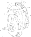
- the drive unit 54 is formed by attaching an electric motor 67 to one surface of a centre case 66 and by attaching a reducer 68 to the other surface of the centre case 66.
- the electric motor 67 includes a bottomed-tube-shaped motor case 49 fastened to the centre case 66, a stator 71 attached to the motor case 49, a motor shaft 73 rotatably supported at one end by the motor case 49 and rotatably supported at the other end by a reducer case 72, and a rotor 74 attached to the motor shaft 73 and surrounded by the stator 71.
- the centre case 66 is a vertically elongate member and has a through hole 75 through which the motor shaft 73 penetrates.
- the reducer 68 includes the bottomed-tube-shaped reducer case 72 fastened to the centre case 66, a small-diameter drive gear 76 provided at a laterally outer end of the motor shaft 73 and housed in the reducer case 72, a large-diameter driven gear 77 rotated by the drive gear 76 directly or via an intermediate gear and housed in the reducer case 72, and the output shaft 59 which is rotated by the driven gear 77 and is configured to rotate the wheel 62.
- An inner race 79 is provided inside the bearing case 56, with rolling elements 78 provided between the inner race 79 and the bearing case 56, and the output shaft 59 is spline-coupled to the inner race 79. Specifically, a laterally outer end of the output shaft 59 is rotatably supported by the bearing case 56, and radial displacement (deflection) is thereby prevented.
- the wheel supporting member 58 is fixed to the front end of the output shaft 59 with a nut 69.
- the wheel 62 is thereby caused to rotate by rotation of the output shaft 59.
- An upward load acting on the rear wheel 13L is transmitted to the wheel supporting member 58, the output shaft 59, and the inner race 79 in this order. Since the wheel supporting member 58 and the inner race 79 are in contact with each other in an axial direction and a protruding length of the output shaft 59 from the inner race 79 is short, the upward load acting on the rear wheel 13L is supported by the inner race 79 and is then supported by the knuckle 43L via the bearing case 56.
- the output shaft 59 can be designed exclusively for rotary power transmission. Accordingly, the diameter of the output shaft 59 can be reduced.
- a brake base plate 81 is fixed to an outer periphery of the bearing case 56. Brake shoes and a shoe expanding part 82 are attached to the brake base plate 81.
- the brake drum 61 is fixed to the wheel supporting member 58. Braking of the rear wheel 13L can be performed by causing the brake shoes to slide in contact with an inner peripheral surface of the brake drum 61.
- a rectangular space 84 surrounded from three sides by the tyre 65, the reducer case 72, and the centre case 66.
- the joint portion 47 for connecting the upper arm portion 48 and the upper arm 41 L to each other is disposed in the rectangular space 84.
- connection work and separation work of the joint portion 47 can be performed easily using the rectangular space 84 as a work space. Accordingly, the work time can be reduced.
- a bearing supporting portion 85 supporting the outer end of the motor shaft 73 is provided in the reducer case 72.
- the bearing supporting portion 85 protrudes into the recessed portion 62a while extending at a lateral side of the knuckle 43L.
- the reducer case 72 (which is part of the drive unit 54) is partially housed in the recessed portion 62a of the wheel 62.
- the drive unit 54 can thus be located closer to the rear wheel (drive wheel) 13L by an amount corresponding to the housed portion. Accordingly, it is possible to dispose part of the drive unit 54 inside the wheel 62 and thereby suppress protrusion of the drive unit 54 to a small degree.
- the rear wheels 13L, 13R are each inclined in such a way that the upper end thereof is located closer to the lateral centre of the vehicle. Accordingly, as shown in Fig. 5 , an uppermost point 54a of the drive unit 54 is below a horizontal line 86 passing through an uppermost point of the tyre 65.
- the drive unit 54 is therefore disposed inside an outer diameter circle 87 of the tyre 65, which is shown by a dotted line.
- the drive unit 54 cannot be seen in a side view of the vehicle, and so the appearance of the vehicle is improved.
- the tyre 65 serves as to protect the drive unit 54, a protection cover for the drive unit 54 can be omitted.
- the electric motor 67 is disposed in such a way that a perpendicular line 90 extending upward from the point of contact between the tyre 65 and the ground and passing through the rotation centre of the wheel 62 (the centre of the output shaft 59) extends upward to overlap the motor shaft 73.
- the upper arm portion 48 extends obliquely upward toward the rear of the vehicle from the knuckle 43L to a position where the upper arm portion 48 does not overlap the drive unit 54, and the upper arm 41 L is connected to the upper end of the upper arm portion 48.
- This arrangement of the upper arm portion 48 eliminates the interference of the drive unit 54 with the upper arm 41 L.
- the electric motor 67 can extend upward. Even when the electric motor 67 is too large to be disposed in the recessed portion 62a of the wheel 62, the electric motor 67 can be easily disposed behind the rear wheel 13L while avoiding interference with the upper arm portion 48 and the upper arm 41.
- an upper half of the motor case 49 has a semicircle shape, and at least part of the joint portion 47 is disposed in an almost-triangular space 91 surrounded by the semicircle (motor case 49), a horizontal line 88 passing through the uppermost point of the semicircle (motor case 49), and a vertical line 89 passing through the rearmost point of the semicircle (motor case 49).
- the joint portion 47 By disposing the joint portion 47 in the almost-triangular space 91 formed in a corner above the semicircle shape, the joint portion 47 can be located close to the motor case 49 while avoiding interference with the motor case 49.
- a terminal portion lid 92 is attached to an upper portion of the motor case 49. Terminal portions can be observed and accessed by removing the terminal portion lid 92.
- a terminal housing chamber 93 is provided in the upper portion of the motor case 49.
- three terminal portions 94 to 96 of U, V, and W are arranged along an outer periphery of the motor case 49 at certain intervals and high-voltage wires 97 to 99 are led out toward the rear of the vehicle.
- a grommet 101 is fitted to a penetrating portion of the high-voltage wires 97 to 99 and a waterproof performance of the terminal housing chamber 93 is thereby maintained.
- the rearmost terminal portion 96 (relative to the vehicle in plan view) is disposed to be offset toward the lateral centre of the vehicle body with respect to the middle terminal portion 95, while the frontmost terminal portion 94 is disposed to be offset toward the wheel with respect to the middle terminal portion 95.
- a crimp terminal 103 is fixed thereto with a bolt 104 via a long socket 102.
- the crimp terminal 103 is fixed thereto with the bolt 104 via a socket 105 having a length which is half the length of the socket 102.
- the crimp terminal 103 is directly fixed thereto with the bolt 104.
- the three terminal portions 94 to 96 are arranged stepwise. Since the terminal portions 94 to 96 are arranged stepwise, end portions of the high-voltage wires 97 to 99 can be fastened to the terminal portions 94 to 96 in straight shapes, without being bent. The work involved in connecting the high-voltage wires 97 to 99 is thereby made easier.
- the three high-voltage wires 97 to 99 are routed along the outer peripheral surface of the motor case 49.
- the motor case 49 is provided with a cover 106 which covers and holds down the high-voltage wires 97 to 99.
- the cover 106 is rotatably fastened to the motor case 49 with a hinge pin 107, and an end thereof is fixed to the motor case 49 with a through pin 108. In other words, routing is made easy by opening (lifting up) the cover 106 during the routing. The cover 106 is closed after the routing.
- the cover 106 is provided at a portion where the high-voltage wires 97 to 99 intersect the upper arm 41 L.
- the high-voltage wires 97 to 99 can be fastened to the motor case 49 by the cover 106.
- the positioning accuracy of the high-voltage wires 97 to 99 is improved. Accordingly, positional relationships of the high-voltage wires with other parts (the upper arm 41 L, for example) can be accurately determined.
- the high-voltage wires 97 to 99 extend from vehicle-mounted batteries (reference numerals 112, 113 in Fig. 12 ) to the terminal portions 94 to 96.
- vehicle-mounted batteries reference numerals 112, 113 in Fig. 12
- the vehicle-mounted batteries do not move vertically relative to the frame of the vehicle.
- the terminal portions 94 to 96 move vertically when the motor case 49 moves vertically.
- a U-shaped portion 109 can be easily formed in the middle of the high-voltage wires 97 to 99 by causing the lead out portions of the high-voltage wires 97 to 99 to gently curve from a horizontal direction to a downward direction along the outer periphery of the motor case 49 as in the embodiment. Even when the terminal portions 94 to 96 vertically move, there is no risk of the high-voltage wires 97 to 99 becoming loose because the high-voltage wires 97 to 99 extend along the motor case 49 and also because the holding effect is provided by the cover 106.
- a box-shaped first battery 112 and second battery 113 are attached to a beam-shaped battery tray 111.
- An interface box 114 is mounted on the second battery 113.
- Two DC-AC convertors 115L, 115R are located on the battery tray 111 side by side in the lateral direction of the vehicle, a controller 116 is located behind the DC-AC convertor 115L.
- a rectangular battery housing space 116 is formed by the left and right side sills 23L, 23R, the front cross frame 24, and the rear cross frame 26.
- the battery tray 111 with the batteries 112, 113 and the like assembled thereto in advance is attached to the battery housing space 116 from below. Then, a battery cover 118 is attached from below.
- the batteries 112, 113 are located within the height dimension of the side sill 23L.
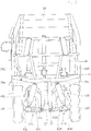
- a 12 V battery 117 is arranged between the left and right rear wheels 13L, 13R.
- the first battery 112, the second battery 113, the DC-AC convertors 115L, 115R, the controller 116, and the 12 V battery 117 are disposed in a plane in this order from the front to the rear of the vehicle, under the floor (reference numeral 14 in Fig. 1 ).
- the rear wheels are the drive wheels; however, the front wheels may be the drive wheels.
- the present invention is preferably applied to a narrow four-wheel vehicle in which a driver seat and a passenger seat are arranged one behind the other.
Landscapes
- Engineering & Computer Science (AREA)
- Mechanical Engineering (AREA)
- Chemical & Material Sciences (AREA)
- Combustion & Propulsion (AREA)
- Transportation (AREA)
- Arrangement Or Mounting Of Propulsion Units For Vehicles (AREA)
Claims (9)
- Véhicule électrique (10) muni de roues motrices gauche et droite (13L, 13R), dans lequel un dispositif de freinage (83) est prévu dans une partie renfoncée (62a) d'une roue (62) de chacune des roues motrices (13L, 13R) et la roue (62) de chacune des roues motrices (13L, 13R) est entraînée par une unité d'entraînement (54), dans lequel
un bras supérieur pouvant osciller verticalement (41L, 41R) et un bras inférieur pouvant osciller verticalement (42L, 42R) s'étendent à partir d'un châssis de carrosserie de véhicule (11) du véhicule électrique (10) dans une direction latérale du véhicule, une rotule (43L, 43R) est reliée à une extrémité distale du bras supérieur (41L, 41R) et à une extrémité distale du bras inférieur (42L, 42R), la roue (62) est supportée en rotation par la rotule (43L, 43R), et l'unité d'entraînement (54) est reliée au côté de la rotule (43L, 43R) plus proche du centre latéral du véhicule ;
caractérisé en ce que
l'unité d'entraînement (54) est une unité dans laquelle un moteur électrique (67) et un réducteur (68) sont intégrés,
le moteur électrique (67) est disposé d'une telle façon qu'une ligne perpendiculaire (90) s'étendant vers le haut à partir du point de contact entre le pneu et le sol et passant par un centre de rotation de la roue (62) s'étend vers le haut pour chevaucher un arbre de moteur (73) dans une vue de profil du véhicule, et
une partie de bras supérieur (48) s'étend obliquement vers le haut vers un arrière du véhicule à partir de la rotule (43L, 43R) entre la roue (62) et l'unité d'entraînement (54) jusqu'à une position où la partie de bras supérieur (48) ne chevauche pas l'unité d'entraînement (54) dans la vue de profil du véhicule, et le bras supérieur (41L, 41R) est relié à une extrémité supérieure de la partie de bras supérieur (48). - Véhicule électrique selon la revendication 1, dans lequel
l'unité d'entraînement (54) est formée en attachant le moteur électrique (67) à une surface d'un carter central (66) et en attachant le réducteur (68) à une autre surface du carter central (66),
le moteur électrique (67) inclut un carter de moteur en forme de tube avec fond (49) fixé au carter central (66), un stator (71) attaché au carter de moteur (49), l'arbre de moteur (73) étant supporté en rotation au niveau d'une extrémité par le carter de moteur (49) et supporté en rotation au niveau d'une autre extrémité par un carter de réducteur (72), et un rotor (74) attaché à l'arbre de moteur (73) et entouré par le stator (71),
le carter central (66) a un trou traversant (75) à travers lequel l'arbre de moteur (73) pénètre,
le réducteur (68) inclut le carter de réducteur en forme de tube avec fond (72) fixé au carter central (66), un engrenage d'entraînement (76) prévu au niveau d'une extrémité extérieure latérale de l'arbre de moteur (73) et logé dans le carter de réducteur (72), un engrenage entraîné (77) mis en rotation par l'engrenage d'entraînement (76) directement ou via un engrenage intermédiaire et logé dans le carter de réducteur (72), et un arbre de sortie (59) mis en rotation par l'engrenage entraîné (77) et mettant la roue (62) en rotation, et
une partie supportant un palier (85) supportant l'autre extrémité de l'arbre de moteur (73) est prévue dans le carter de réducteur (72) et dépasse dans la partie renfoncée (62a) de la roue (62) tout en s'étendant au niveau d'un côté latéralement extérieur de la rotule (43L, 43R). - Véhicule électrique selon la revendication 1 ou la revendication 2, dans lequel l'unité d'entraînement (54) est disposée à l'intérieur d'un cercle de diamètre extérieur (87) d'un pneu (65) de chacune des roues motrices (13L, 13R) dans une vue de profil du véhicule.
- Véhicule électrique selon la revendication 3, dans lequel un espace rectangulaire (84) entouré de trois côtés par le pneu (65), le carter de réducteur (72) et le carter central (66) dans une vue de face du véhicule est formé, et une partie formant articulation (47) entre la partie de bras supérieur (48) et le bras supérieur (41L, 41R) est disposée dans l'espace rectangulaire (84).
- Véhicule électrique selon la revendication 4, dans lequel, dans la vue de profil du véhicule, une moitié supérieure du carter de moteur (49) a une forme semi-circulaire et au moins un morceau de la partie formant articulation (47) est disposé dans un espace presque triangulaire (91) entouré par le demi-cercle, une ligne horizontale (88) passant par le point supérieur du demi-cercle, et une ligne verticale (89) passant par le point le plus en arrière du demi-cercle.
- Véhicule électrique selon la revendication 4 ou la revendication 5, dans lequel le bras supérieur (41L, 41R) est un élément en forme de V ayant une partie intermédiaire qui dépasse vers le haut, et une partie de connexion côté châssis de carrosserie de véhicule (45) du bras supérieur (41L, 41R) est au-dessous de la partie formant articulation (47).
- Véhicule électrique selon la revendication 5 ou la revendication 6 lorsque dépendante de la revendication 5, dans lequel une partie terminale (94 à 96) est prévue dans une partie supérieure du carter de moteur (49) et un câble haute tension (97 à 99) s'étendant depuis la partie terminale (94 à 96) est acheminé le long d'une surface périphérique extérieure du carter de moteur (49).
- Véhicule électrique selon la revendication 7, dans lequel la partie terminale (94 à 96) inclut trois parties terminales (94 à 96) de U, V et W, les trois parties terminales (94 à 96) sont agencées le long de la surface périphérique extérieure du carter de moteur (49) à intervalles, le câble haute tension (97 à 99) est amené vers l'arrière du véhicule, la partie terminale la plus en arrière (96) est disposée pour être latéralement décalée vers le centre de la carrosserie de véhicule par rapport à la partie terminale médiane (95), et la partie terminale la plus en avant (94) est disposée pour être latéralement décalée vers la roue par rapport à la partie terminale médiane (95).
- Véhicule électrique selon la revendication 7 ou 8, dans lequel un couvercle (106) couvrant et maintenant vers le bas le câble haute tension (97 à 99) est prévu dans une partie du carter de moteur (49) où le câble haute tension (97 à 99) croise le bras supérieur (41L, 41R).
Applications Claiming Priority (1)
| Application Number | Priority Date | Filing Date | Title |
|---|---|---|---|
| JP2012080826A JP5872358B2 (ja) | 2012-03-30 | 2012-03-30 | 電動車両 |
Publications (3)
| Publication Number | Publication Date |
|---|---|
| EP2644414A2 EP2644414A2 (fr) | 2013-10-02 |
| EP2644414A3 EP2644414A3 (fr) | 2015-03-25 |
| EP2644414B1 true EP2644414B1 (fr) | 2017-05-24 |
Family
ID=47843092
Family Applications (1)
| Application Number | Title | Priority Date | Filing Date |
|---|---|---|---|
| EP13157550.8A Not-in-force EP2644414B1 (fr) | 2012-03-30 | 2013-03-04 | Véhicule électrique |
Country Status (5)
| Country | Link |
|---|---|
| US (1) | US8910735B2 (fr) |
| EP (1) | EP2644414B1 (fr) |
| JP (1) | JP5872358B2 (fr) |
| CN (1) | CN103358868B (fr) |
| ES (1) | ES2628910T3 (fr) |
Families Citing this family (29)
| Publication number | Priority date | Publication date | Assignee | Title |
|---|---|---|---|---|
| EP2993066B1 (fr) * | 2013-04-30 | 2018-09-05 | Nissan Motor Co., Ltd | Dispositif de suspension de roue menée de moteur-roue |
| US9914348B2 (en) * | 2014-06-30 | 2018-03-13 | Nissan North America, Inc. | Electric drive motor assembly for a wheel |
| US9783257B2 (en) * | 2014-12-31 | 2017-10-10 | Arcimoto, Inc. | Narrow ultra efficient three wheeled vehicle with automotive class feel and handlebar steering |
| US9994276B2 (en) * | 2014-12-31 | 2018-06-12 | Arcimoto, Inc. | Narrow ultra efficient three wheeled vehicle with automotive class feel |
| JP2017150640A (ja) * | 2016-02-26 | 2017-08-31 | Ntn株式会社 | インホイールモータ駆動装置 |
| JP6956464B2 (ja) | 2016-03-04 | 2021-11-02 | Ntn株式会社 | インホイールモータ駆動装置 |
| JP6125066B1 (ja) | 2016-03-08 | 2017-05-10 | Ntn株式会社 | インホイールモータ駆動装置 |
| JP6792995B2 (ja) * | 2016-03-14 | 2020-12-02 | Ntn株式会社 | インホイールモータ駆動装置 |
| US10308132B2 (en) * | 2016-05-09 | 2019-06-04 | Nikola Corporation | Electric utility terrain vehicle |
| US10581126B2 (en) | 2016-05-09 | 2020-03-03 | Nikola Corporation | Electric battery assembly |
| US10497998B2 (en) * | 2016-05-09 | 2019-12-03 | Nikola Corporation | Electric battery assembly |
| JP6794211B2 (ja) | 2016-10-14 | 2020-12-02 | Ntn株式会社 | インホイールモータ駆動装置 |
| JP6821385B2 (ja) | 2016-10-19 | 2021-01-27 | Ntn株式会社 | インホイールモータ駆動装置 |
| JP6786354B2 (ja) | 2016-10-31 | 2020-11-18 | Ntn株式会社 | インホイールモータ駆動装置 |
| US11084371B2 (en) * | 2017-01-10 | 2021-08-10 | Showa Corporation | Motor drive device |
| JP2018192887A (ja) * | 2017-05-16 | 2018-12-06 | トヨタ自動車株式会社 | インホイールモータ内蔵非操舵駆動輪のサスペンション装置 |
| CN111801235B (zh) * | 2018-03-09 | 2023-09-29 | 丰田自动车株式会社 | 轮轴结构 |
| JP7024595B2 (ja) * | 2018-05-16 | 2022-02-24 | トヨタ自動車株式会社 | 車輪駆動ユニット |
| US10559793B2 (en) * | 2018-05-17 | 2020-02-11 | Ford Global Technologies, Llc | Battery array retention method and assembly |
| JP7079347B2 (ja) * | 2018-12-26 | 2022-06-01 | 本田技研工業株式会社 | 電動駆動ユニット及び電動車両 |
| JP7714467B2 (ja) | 2019-03-05 | 2025-07-29 | クーデル・ソシエテ・アノニム | 車両の姿勢を制御するシステム及び方法、並びに当該システムを備える車両 |
| JP2020192952A (ja) * | 2019-05-30 | 2020-12-03 | ヤマハ発動機株式会社 | インホイールモータユニット及び電動車両 |
| JP7380460B2 (ja) | 2020-07-13 | 2023-11-15 | 住友電装株式会社 | 足回り用配線モジュール及び足回り用配線モジュールの配索構造 |
| JP7834426B2 (ja) | 2020-07-13 | 2026-03-24 | 住友電装株式会社 | 足回り用配線モジュール及び足回り用配線モジュールの配索構造 |
| JP7487591B2 (ja) * | 2020-07-13 | 2024-05-21 | 住友電装株式会社 | 配線部材の配索構造 |
| US11498435B2 (en) * | 2020-07-30 | 2022-11-15 | Dana Heavy Vehicle Systems Group, Llc | Systems and methods for an electrified heavy-duty vehicle |
| US11485215B1 (en) | 2021-12-09 | 2022-11-01 | Workhorse Group Inc. | Land vehicles incorporating electric motors and methods therefor |
| US20250135857A1 (en) * | 2023-10-30 | 2025-05-01 | Kubota Corporation | Electric work vehicle |
| US12570162B2 (en) * | 2023-10-30 | 2026-03-10 | Kubota Corporation | Electric work vehicle |
Family Cites Families (13)
| Publication number | Priority date | Publication date | Assignee | Title |
|---|---|---|---|---|
| FR2679842A1 (fr) * | 1991-07-29 | 1993-02-05 | Shm Management Services Ag | Module de roulement moteur, notamment pour vehicule automobile. |
| FR2776966B1 (fr) * | 1998-04-06 | 2000-05-05 | Conception & Dev Michelin Sa | Roue comportant un ou plusieurs moteurs de traction integres |
| JP3638586B2 (ja) * | 2001-04-16 | 2005-04-13 | 株式会社ブリヂストン | インホイールモータの取付方法及びインホイールモータシステム |
| JP2004090822A (ja) * | 2002-09-02 | 2004-03-25 | Toyota Motor Corp | 車両用モータ配備車輪装置 |
| JP4348941B2 (ja) * | 2002-11-26 | 2009-10-21 | 日産自動車株式会社 | 車輪用回転電機の取付構造 |
| JP2005295773A (ja) * | 2004-04-05 | 2005-10-20 | Bridgestone Corp | インホイールモータの取付方法 |
| JP4276579B2 (ja) * | 2004-05-17 | 2009-06-10 | トヨタ自動車株式会社 | インホイールモータに設けられる部品の搭載構造 |
| JP4139353B2 (ja) * | 2004-05-25 | 2008-08-27 | トヨタ自動車株式会社 | 車輪支持装置 |
| JP2006188153A (ja) * | 2005-01-06 | 2006-07-20 | Toyota Motor Corp | インホイールモータ |
| JP4550631B2 (ja) | 2005-03-11 | 2010-09-22 | 本田技研工業株式会社 | 車両用ホイール駆動装置 |
| JP4820189B2 (ja) * | 2006-03-09 | 2011-11-24 | 本田技研工業株式会社 | 車両用ホイール駆動装置の配置構造 |
| JP2008183956A (ja) * | 2007-01-29 | 2008-08-14 | Mazda Motor Corp | 車両用駆動装置の配設構造 |
| CN101638052B (zh) * | 2009-08-21 | 2012-01-04 | 山东大学 | 独立驱动、转向、悬挂和制动的一体化车轮总成 |
-
2012
- 2012-03-30 JP JP2012080826A patent/JP5872358B2/ja not_active Expired - Fee Related
-
2013
- 2013-03-04 EP EP13157550.8A patent/EP2644414B1/fr not_active Not-in-force
- 2013-03-04 ES ES13157550.8T patent/ES2628910T3/es active Active
- 2013-03-21 CN CN201310092256.5A patent/CN103358868B/zh not_active Expired - Fee Related
- 2013-03-27 US US13/851,129 patent/US8910735B2/en active Active
Also Published As
| Publication number | Publication date |
|---|---|
| EP2644414A3 (fr) | 2015-03-25 |
| JP5872358B2 (ja) | 2016-03-01 |
| ES2628910T3 (es) | 2017-08-04 |
| EP2644414A2 (fr) | 2013-10-02 |
| CN103358868A (zh) | 2013-10-23 |
| US8910735B2 (en) | 2014-12-16 |
| CN103358868B (zh) | 2016-04-06 |
| JP2013209016A (ja) | 2013-10-10 |
| US20130284528A1 (en) | 2013-10-31 |
Similar Documents
| Publication | Publication Date | Title |
|---|---|---|
| EP2644414B1 (fr) | Véhicule électrique | |
| EP2644415B1 (fr) | Véhicule électrique | |
| EP4074533B1 (fr) | Ensemble essieu ayant un module de moteur électrique | |
| KR20130111378A (ko) | 전동 삼륜 차량 | |
| CN111114676B (zh) | 跨骑型电动车辆 | |
| WO2016080214A1 (fr) | Élément de protection de batterie | |
| US20140014425A1 (en) | In-wheel motor apparatus | |
| JP2008168804A (ja) | 車両用駆動装置の配設構造 | |
| JP2013144509A (ja) | インホイールモータ駆動車輪のモータ給電線配索構造 | |
| JP6423153B2 (ja) | 電動式転舵装置搭載車両 | |
| KR20230098457A (ko) | 주행용 모듈 및 그 주행용 모듈을 포함하는 모빌리티 | |
| JP2019189054A (ja) | 電動三輪車両 | |
| JP2008168803A (ja) | 車両用駆動装置の配設構造 | |
| JPWO2019044119A1 (ja) | 車両 | |
| JP6694484B2 (ja) | 車両 | |
| CN112004740B (zh) | 电动车辆 | |
| JP5847872B2 (ja) | ウインチ付車両 | |
| JP7380460B2 (ja) | 足回り用配線モジュール及び足回り用配線モジュールの配索構造 | |
| JP2008168802A (ja) | 車両用駆動装置の配設構造 | |
| EP2644462A2 (fr) | Véhicule comprenant un levier de frein de stationnement qui est approprié pour un véhicule de petite taille étroite | |
| JP2014151891A (ja) | 電気動力車両の車体構造 | |
| JP2012046077A (ja) | 電動式車両 | |
| JP2010195147A (ja) | 車載モータ用ケーブルの配策構造 | |
| JP2026029230A (ja) | 電動車両の前部構造 | |
| JP2008168801A (ja) | 車両用駆動装置の配設構造 |
Legal Events
| Date | Code | Title | Description |
|---|---|---|---|
| PUAI | Public reference made under article 153(3) epc to a published international application that has entered the european phase |
Free format text: ORIGINAL CODE: 0009012 |
|
| 17P | Request for examination filed |
Effective date: 20130304 |
|
| AK | Designated contracting states |
Kind code of ref document: A2 Designated state(s): AL AT BE BG CH CY CZ DE DK EE ES FI FR GB GR HR HU IE IS IT LI LT LU LV MC MK MT NL NO PL PT RO RS SE SI SK SM TR |
|
| AX | Request for extension of the european patent |
Extension state: BA ME |
|
| PUAL | Search report despatched |
Free format text: ORIGINAL CODE: 0009013 |
|
| AK | Designated contracting states |
Kind code of ref document: A3 Designated state(s): AL AT BE BG CH CY CZ DE DK EE ES FI FR GB GR HR HU IE IS IT LI LT LU LV MC MK MT NL NO PL PT RO RS SE SI SK SM TR |
|
| AX | Request for extension of the european patent |
Extension state: BA ME |
|
| RIC1 | Information provided on ipc code assigned before grant |
Ipc: B60G 3/20 20060101AFI20150219BHEP Ipc: B60K 7/00 20060101ALI20150219BHEP |
|
| GRAP | Despatch of communication of intention to grant a patent |
Free format text: ORIGINAL CODE: EPIDOSNIGR1 |
|
| INTG | Intention to grant announced |
Effective date: 20160725 |
|
| GRAS | Grant fee paid |
Free format text: ORIGINAL CODE: EPIDOSNIGR3 |
|
| GRAA | (expected) grant |
Free format text: ORIGINAL CODE: 0009210 |
|
| AK | Designated contracting states |
Kind code of ref document: B1 Designated state(s): AL AT BE BG CH CY CZ DE DK EE ES FI FR GB GR HR HU IE IS IT LI LT LU LV MC MK MT NL NO PL PT RO RS SE SI SK SM TR |
|
| REG | Reference to a national code |
Ref country code: GB Ref legal event code: FG4D |
|
| REG | Reference to a national code |
Ref country code: CH Ref legal event code: EP |
|
| REG | Reference to a national code |
Ref country code: IE Ref legal event code: FG4D |
|
| REG | Reference to a national code |
Ref country code: AT Ref legal event code: REF Ref document number: 895839 Country of ref document: AT Kind code of ref document: T Effective date: 20170615 |
|
| REG | Reference to a national code |
Ref country code: DE Ref legal event code: R096 Ref document number: 602013021466 Country of ref document: DE |
|
| REG | Reference to a national code |
Ref country code: ES Ref legal event code: FG2A Ref document number: 2628910 Country of ref document: ES Kind code of ref document: T3 Effective date: 20170804 |
|
| REG | Reference to a national code |
Ref country code: NL Ref legal event code: MP Effective date: 20170524 |
|
| REG | Reference to a national code |
Ref country code: LT Ref legal event code: MG4D |
|
| REG | Reference to a national code |
Ref country code: AT Ref legal event code: MK05 Ref document number: 895839 Country of ref document: AT Kind code of ref document: T Effective date: 20170524 |
|
| PG25 | Lapsed in a contracting state [announced via postgrant information from national office to epo] |
Ref country code: LT Free format text: LAPSE BECAUSE OF FAILURE TO SUBMIT A TRANSLATION OF THE DESCRIPTION OR TO PAY THE FEE WITHIN THE PRESCRIBED TIME-LIMIT Effective date: 20170524 Ref country code: FI Free format text: LAPSE BECAUSE OF FAILURE TO SUBMIT A TRANSLATION OF THE DESCRIPTION OR TO PAY THE FEE WITHIN THE PRESCRIBED TIME-LIMIT Effective date: 20170524 Ref country code: HR Free format text: LAPSE BECAUSE OF FAILURE TO SUBMIT A TRANSLATION OF THE DESCRIPTION OR TO PAY THE FEE WITHIN THE PRESCRIBED TIME-LIMIT Effective date: 20170524 Ref country code: NO Free format text: LAPSE BECAUSE OF FAILURE TO SUBMIT A TRANSLATION OF THE DESCRIPTION OR TO PAY THE FEE WITHIN THE PRESCRIBED TIME-LIMIT Effective date: 20170824 Ref country code: AT Free format text: LAPSE BECAUSE OF FAILURE TO SUBMIT A TRANSLATION OF THE DESCRIPTION OR TO PAY THE FEE WITHIN THE PRESCRIBED TIME-LIMIT Effective date: 20170524 Ref country code: GR Free format text: LAPSE BECAUSE OF FAILURE TO SUBMIT A TRANSLATION OF THE DESCRIPTION OR TO PAY THE FEE WITHIN THE PRESCRIBED TIME-LIMIT Effective date: 20170825 |
|
| PG25 | Lapsed in a contracting state [announced via postgrant information from national office to epo] |
Ref country code: LV Free format text: LAPSE BECAUSE OF FAILURE TO SUBMIT A TRANSLATION OF THE DESCRIPTION OR TO PAY THE FEE WITHIN THE PRESCRIBED TIME-LIMIT Effective date: 20170524 Ref country code: SE Free format text: LAPSE BECAUSE OF FAILURE TO SUBMIT A TRANSLATION OF THE DESCRIPTION OR TO PAY THE FEE WITHIN THE PRESCRIBED TIME-LIMIT Effective date: 20170524 Ref country code: BG Free format text: LAPSE BECAUSE OF FAILURE TO SUBMIT A TRANSLATION OF THE DESCRIPTION OR TO PAY THE FEE WITHIN THE PRESCRIBED TIME-LIMIT Effective date: 20170824 Ref country code: NL Free format text: LAPSE BECAUSE OF FAILURE TO SUBMIT A TRANSLATION OF THE DESCRIPTION OR TO PAY THE FEE WITHIN THE PRESCRIBED TIME-LIMIT Effective date: 20170524 Ref country code: IS Free format text: LAPSE BECAUSE OF FAILURE TO SUBMIT A TRANSLATION OF THE DESCRIPTION OR TO PAY THE FEE WITHIN THE PRESCRIBED TIME-LIMIT Effective date: 20170924 Ref country code: RS Free format text: LAPSE BECAUSE OF FAILURE TO SUBMIT A TRANSLATION OF THE DESCRIPTION OR TO PAY THE FEE WITHIN THE PRESCRIBED TIME-LIMIT Effective date: 20170524 |
|
| REG | Reference to a national code |
Ref country code: FR Ref legal event code: PLFP Year of fee payment: 6 |
|
| PG25 | Lapsed in a contracting state [announced via postgrant information from national office to epo] |
Ref country code: DK Free format text: LAPSE BECAUSE OF FAILURE TO SUBMIT A TRANSLATION OF THE DESCRIPTION OR TO PAY THE FEE WITHIN THE PRESCRIBED TIME-LIMIT Effective date: 20170524 Ref country code: CZ Free format text: LAPSE BECAUSE OF FAILURE TO SUBMIT A TRANSLATION OF THE DESCRIPTION OR TO PAY THE FEE WITHIN THE PRESCRIBED TIME-LIMIT Effective date: 20170524 Ref country code: EE Free format text: LAPSE BECAUSE OF FAILURE TO SUBMIT A TRANSLATION OF THE DESCRIPTION OR TO PAY THE FEE WITHIN THE PRESCRIBED TIME-LIMIT Effective date: 20170524 Ref country code: SK Free format text: LAPSE BECAUSE OF FAILURE TO SUBMIT A TRANSLATION OF THE DESCRIPTION OR TO PAY THE FEE WITHIN THE PRESCRIBED TIME-LIMIT Effective date: 20170524 Ref country code: RO Free format text: LAPSE BECAUSE OF FAILURE TO SUBMIT A TRANSLATION OF THE DESCRIPTION OR TO PAY THE FEE WITHIN THE PRESCRIBED TIME-LIMIT Effective date: 20170524 |
|
| REG | Reference to a national code |
Ref country code: DE Ref legal event code: R097 Ref document number: 602013021466 Country of ref document: DE |
|
| PG25 | Lapsed in a contracting state [announced via postgrant information from national office to epo] |
Ref country code: PL Free format text: LAPSE BECAUSE OF FAILURE TO SUBMIT A TRANSLATION OF THE DESCRIPTION OR TO PAY THE FEE WITHIN THE PRESCRIBED TIME-LIMIT Effective date: 20170524 Ref country code: SM Free format text: LAPSE BECAUSE OF FAILURE TO SUBMIT A TRANSLATION OF THE DESCRIPTION OR TO PAY THE FEE WITHIN THE PRESCRIBED TIME-LIMIT Effective date: 20170524 |
|
| PLBE | No opposition filed within time limit |
Free format text: ORIGINAL CODE: 0009261 |
|
| STAA | Information on the status of an ep patent application or granted ep patent |
Free format text: STATUS: NO OPPOSITION FILED WITHIN TIME LIMIT |
|
| 26N | No opposition filed |
Effective date: 20180227 |
|
| PG25 | Lapsed in a contracting state [announced via postgrant information from national office to epo] |
Ref country code: SI Free format text: LAPSE BECAUSE OF FAILURE TO SUBMIT A TRANSLATION OF THE DESCRIPTION OR TO PAY THE FEE WITHIN THE PRESCRIBED TIME-LIMIT Effective date: 20170524 |
|
| REG | Reference to a national code |
Ref country code: CH Ref legal event code: PL |
|
| GBPC | Gb: european patent ceased through non-payment of renewal fee |
Effective date: 20180304 |
|
| PG25 | Lapsed in a contracting state [announced via postgrant information from national office to epo] |
Ref country code: MC Free format text: LAPSE BECAUSE OF FAILURE TO SUBMIT A TRANSLATION OF THE DESCRIPTION OR TO PAY THE FEE WITHIN THE PRESCRIBED TIME-LIMIT Effective date: 20170524 |
|
| REG | Reference to a national code |
Ref country code: BE Ref legal event code: MM Effective date: 20180331 |
|
| REG | Reference to a national code |
Ref country code: IE Ref legal event code: MM4A |
|
| PG25 | Lapsed in a contracting state [announced via postgrant information from national office to epo] |
Ref country code: LU Free format text: LAPSE BECAUSE OF NON-PAYMENT OF DUE FEES Effective date: 20180304 |
|
| PG25 | Lapsed in a contracting state [announced via postgrant information from national office to epo] |
Ref country code: IE Free format text: LAPSE BECAUSE OF NON-PAYMENT OF DUE FEES Effective date: 20180304 |
|
| PG25 | Lapsed in a contracting state [announced via postgrant information from national office to epo] |
Ref country code: BE Free format text: LAPSE BECAUSE OF NON-PAYMENT OF DUE FEES Effective date: 20180331 Ref country code: LI Free format text: LAPSE BECAUSE OF NON-PAYMENT OF DUE FEES Effective date: 20180331 Ref country code: GB Free format text: LAPSE BECAUSE OF NON-PAYMENT OF DUE FEES Effective date: 20180304 Ref country code: CH Free format text: LAPSE BECAUSE OF NON-PAYMENT OF DUE FEES Effective date: 20180331 |
|
| PGFP | Annual fee paid to national office [announced via postgrant information from national office to epo] |
Ref country code: FR Payment date: 20190111 Year of fee payment: 7 |
|
| PGFP | Annual fee paid to national office [announced via postgrant information from national office to epo] |
Ref country code: ES Payment date: 20190401 Year of fee payment: 7 |
|
| REG | Reference to a national code |
Ref country code: DE Ref legal event code: R084 Ref document number: 602013021466 Country of ref document: DE |
|
| PG25 | Lapsed in a contracting state [announced via postgrant information from national office to epo] |
Ref country code: MT Free format text: LAPSE BECAUSE OF NON-PAYMENT OF DUE FEES Effective date: 20180304 |
|
| PG25 | Lapsed in a contracting state [announced via postgrant information from national office to epo] |
Ref country code: TR Free format text: LAPSE BECAUSE OF FAILURE TO SUBMIT A TRANSLATION OF THE DESCRIPTION OR TO PAY THE FEE WITHIN THE PRESCRIBED TIME-LIMIT Effective date: 20170524 |
|
| PGFP | Annual fee paid to national office [announced via postgrant information from national office to epo] |
Ref country code: IT Payment date: 20200221 Year of fee payment: 8 |
|
| PG25 | Lapsed in a contracting state [announced via postgrant information from national office to epo] |
Ref country code: HU Free format text: LAPSE BECAUSE OF FAILURE TO SUBMIT A TRANSLATION OF THE DESCRIPTION OR TO PAY THE FEE WITHIN THE PRESCRIBED TIME-LIMIT; INVALID AB INITIO Effective date: 20130304 Ref country code: PT Free format text: LAPSE BECAUSE OF FAILURE TO SUBMIT A TRANSLATION OF THE DESCRIPTION OR TO PAY THE FEE WITHIN THE PRESCRIBED TIME-LIMIT Effective date: 20170524 |
|
| PG25 | Lapsed in a contracting state [announced via postgrant information from national office to epo] |
Ref country code: MK Free format text: LAPSE BECAUSE OF NON-PAYMENT OF DUE FEES Effective date: 20170524 Ref country code: CY Free format text: LAPSE BECAUSE OF FAILURE TO SUBMIT A TRANSLATION OF THE DESCRIPTION OR TO PAY THE FEE WITHIN THE PRESCRIBED TIME-LIMIT Effective date: 20170524 |
|
| PG25 | Lapsed in a contracting state [announced via postgrant information from national office to epo] |
Ref country code: AL Free format text: LAPSE BECAUSE OF FAILURE TO SUBMIT A TRANSLATION OF THE DESCRIPTION OR TO PAY THE FEE WITHIN THE PRESCRIBED TIME-LIMIT Effective date: 20170524 |
|
| PG25 | Lapsed in a contracting state [announced via postgrant information from national office to epo] |
Ref country code: FR Free format text: LAPSE BECAUSE OF NON-PAYMENT OF DUE FEES Effective date: 20200331 |
|
| REG | Reference to a national code |
Ref country code: DE Ref legal event code: R082 Ref document number: 602013021466 Country of ref document: DE |
|
| PGFP | Annual fee paid to national office [announced via postgrant information from national office to epo] |
Ref country code: DE Payment date: 20210216 Year of fee payment: 9 |
|
| REG | Reference to a national code |
Ref country code: ES Ref legal event code: FD2A Effective date: 20210726 |
|
| PG25 | Lapsed in a contracting state [announced via postgrant information from national office to epo] |
Ref country code: ES Free format text: LAPSE BECAUSE OF NON-PAYMENT OF DUE FEES Effective date: 20200305 |
|
| PG25 | Lapsed in a contracting state [announced via postgrant information from national office to epo] |
Ref country code: IT Free format text: LAPSE BECAUSE OF NON-PAYMENT OF DUE FEES Effective date: 20210304 |
|
| REG | Reference to a national code |
Ref country code: DE Ref legal event code: R119 Ref document number: 602013021466 Country of ref document: DE |
|
| PG25 | Lapsed in a contracting state [announced via postgrant information from national office to epo] |
Ref country code: DE Free format text: LAPSE BECAUSE OF NON-PAYMENT OF DUE FEES Effective date: 20221001 |