EP2644479A2 - Fahrgestellrahmenverbindung für ein elektrisches Fahrzeug für behinderte Personen - Google Patents
Fahrgestellrahmenverbindung für ein elektrisches Fahrzeug für behinderte Personen Download PDFInfo
- Publication number
- EP2644479A2 EP2644479A2 EP12002930.1A EP12002930A EP2644479A2 EP 2644479 A2 EP2644479 A2 EP 2644479A2 EP 12002930 A EP12002930 A EP 12002930A EP 2644479 A2 EP2644479 A2 EP 2644479A2
- Authority
- EP
- European Patent Office
- Prior art keywords
- chassis frame
- reinforcement member
- welding
- assembly
- fastening
- Prior art date
- Legal status (The legal status is an assumption and is not a legal conclusion. Google has not performed a legal analysis and makes no representation as to the accuracy of the status listed.)
- Withdrawn
Links
- 230000002787 reinforcement Effects 0.000 claims abstract description 71
- 238000003466 welding Methods 0.000 claims abstract description 60
- 229910052782 aluminium Inorganic materials 0.000 claims abstract description 23
- XAGFODPZIPBFFR-UHFFFAOYSA-N aluminium Chemical compound [Al] XAGFODPZIPBFFR-UHFFFAOYSA-N 0.000 claims abstract description 23
- 238000000034 method Methods 0.000 description 7
- XKRFYHLGVUSROY-UHFFFAOYSA-N Argon Chemical compound [Ar] XKRFYHLGVUSROY-UHFFFAOYSA-N 0.000 description 2
- 239000000956 alloy Substances 0.000 description 2
- 229910045601 alloy Inorganic materials 0.000 description 2
- 238000009826 distribution Methods 0.000 description 2
- 230000003014 reinforcing effect Effects 0.000 description 2
- 229910052786 argon Inorganic materials 0.000 description 1
- 238000010276 construction Methods 0.000 description 1
- 239000000446 fuel Substances 0.000 description 1
- 238000004519 manufacturing process Methods 0.000 description 1
- 229910052751 metal Inorganic materials 0.000 description 1
- 239000002184 metal Substances 0.000 description 1
- 229920003002 synthetic resin Polymers 0.000 description 1
- 239000000057 synthetic resin Substances 0.000 description 1
Images




Classifications
-
- B—PERFORMING OPERATIONS; TRANSPORTING
- B62—LAND VEHICLES FOR TRAVELLING OTHERWISE THAN ON RAILS
- B62D—MOTOR VEHICLES; TRAILERS
- B62D27/00—Connections between superstructure or understructure sub-units
- B62D27/02—Connections between superstructure or understructure sub-units rigid
- B62D27/023—Assembly of structural joints
-
- B—PERFORMING OPERATIONS; TRANSPORTING
- B62—LAND VEHICLES FOR TRAVELLING OTHERWISE THAN ON RAILS
- B62D—MOTOR VEHICLES; TRAILERS
- B62D21/00—Understructures, i.e. chassis frame on which a vehicle body may be mounted
- B62D21/02—Understructures, i.e. chassis frame on which a vehicle body may be mounted comprising longitudinally or transversely arranged frame members
-
- B—PERFORMING OPERATIONS; TRANSPORTING
- B62—LAND VEHICLES FOR TRAVELLING OTHERWISE THAN ON RAILS
- B62D—MOTOR VEHICLES; TRAILERS
- B62D29/00—Superstructures, understructures, or sub-units thereof, characterised by the material thereof
- B62D29/008—Superstructures, understructures, or sub-units thereof, characterised by the material thereof predominantly of light alloys, e.g. extruded
-
- B—PERFORMING OPERATIONS; TRANSPORTING
- B62—LAND VEHICLES FOR TRAVELLING OTHERWISE THAN ON RAILS
- B62D—MOTOR VEHICLES; TRAILERS
- B62D31/00—Superstructures for passenger vehicles
- B62D31/003—Superstructures for passenger vehicles compact cars, e.g. city cars
Definitions
- the present invention relates to a chassis frame for an electrical vehicle for a disabled person and, more particularly, to a chassis frame assembly structure for an electrical vehicle, wherein the welding part of the chassis frame made of aluminum (Al) is fixed more firmly by reinforcement so that an impact distribution at the time of a collision is uniformly distributed, thereby being capable of preventing casualties by preventing a crack from occurring in the welding part.
- Al aluminum
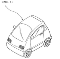
- the recent electrical vehicle for a disabled person includes a single seater electrical vehicle as shown in FIG. 1 .
- the electrical vehicle 1 for a disabled person is driven using a battery method without using fuel as in a common vehicle. Accordingly, there is a tendency to reduce the weight of the electrical vehicle in order to increase the distance covered at the time of fabrication.
- chassis frames 2 of the electrical vehicle are made of an aluminum (Al) alloy as shown in FIG. 2 , the connection parts of the chassis frames 2 are welded using an argon or arc welding method, and thus the chassis frames 2 are integrally assembled while forming a welding assembly unit 3.
- the weight of the electrical vehicle 1 for a disabled person can be reduced because the chassis of the electrical vehicle 1 for a disabled person 1 are assembled by welding using the frames 2 made of aluminum (Al) as described above. Accordingly, the consumption of the battery can be reduced and the distance covered can be increased because the weight of the electrical vehicle for a disabled person is reduced.
- the weight of the electrical vehicle 1 may be reduced to some extent, but the aluminum chassis frame 2 has relatively weak impact strength. For this reason, if the electrical vehicle is subject to a frontal collision while driving and the impact load is applied to the welding parts, a crack is generated in the welding assembly unit 3 and thus the welding part is easily deformed. In an even worse situation, the aluminum chassis frames 2 are broken and the broken parts invade the interior of the vehicle, thereby severely injuring a passenger.
- the conventional aluminum chassis frame 2 is problematic in that, when the vehicle collides, the vehicle body may be greatly damaged because the aluminum chassis frame 2 has low stiffness against an impact and the reliability and safety of a product are deteriorated because the safety of a passenger and a driver cannot be guaranteed. Accordingly, there is a need for a method of improving the chassis frame assembly structure.
- the present invention relates to a chassis frame assembly structure for an electrical vehicle for a disabled person, wherein the welding assembly part of the chassis frame made of aluminum (Al) is fixed more firmly by reinforcement so that an impact distribution at the time of a collision is uniformly distributed, thereby being capable of preventing casualties by preventing a crack from occurring in the welding assembly part due to the collision impact and thus preventing the deformation or breakage of the chassis frames.
- Al aluminum
- a chassis frame assembly structure for an electrical vehicle for a disabled person, in which welding assembly units are formed by attachment and welding at respective portions in each of which channel-shaped frames made of aluminum and each configured to have a hollow structure are coupled, including a plurality of fastening holes formed at proper interval close to the welding assembly unit of the chassis frames; reinforcement members each configured to have a channel shape, surround the periphery of the welding assembly unit of the chassis frame, and have a plurality of assembly holes, corresponding to the respective fastening holes, formed at proper intervals in one face of the reinforcement member; and fastening members assembled with the assembly holes and the fastening holes, wherein the reinforcement member is positioned at the outside of the chassis frame and integrally assembled with the chassis frame by the fastening members.
- each of the reinforcement members is the square-sectional welding assembly unit of the chassis frame having a straight-line section and formed of a ⁇ -shaped sectional channel.
- the assembly holes are formed in both faces of the reinforcement member.
- each of the reinforcement members is the square-sectional welding assembly unit of the chassis frame having a straight-line section and formed of a ⁇ -shaped sectional channel.
- the assembly holes are formed in both faces of the reinforcement member.
- each of the reinforcement members may further include a second welding assembly unit made of the same aluminum (Al) as the chassis frame, and a corner part where the chassis frames and the second welding assembly unit adjoin each other may be welded and processed.
- Al aluminum
- Each of the fastening members includes a fastening bolt and a nut.
- the fastening bolt penetrates the chassis frame and the reinforcement member, and the fastening bolt may be then assembled by the nut on the opposite side or the fastening hole may be subject to tap processing and screwed using only the fastening bolt.
- FIG. 1 is a perspective view showing an external appearance of an electrical vehicle for a disabled person
- FIG. 2 is a perspective view showing the chassis frame assembly structure and the welding assembly unit for a conventional electrical vehicle for a disabled person;
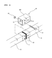
- FIG. 3 is a perspective view showing a chassis frame assembly structure for an electrical vehicle for a disabled person according to an embodiment of the present invention
- FIG. 4 is an exploded perspective view showing the assembly structure of a ⁇ -shaped channel reinforcement member according to an embodiment of the present invention
- FIGS. 5 and 6 are a longitudinal section view and a front view showing the assembly structure of the ⁇ -shaped channel reinforcement member
- FIG. 7 is an exploded perspective view showing the assembly structure of a ⁇ -shaped channel reinforcement member according to another embodiment of the present invention.
- FIGS. 8 and 9 are a longitudinal section view and a front view showing the assembly structure of the ⁇ -shaped channel reinforcement member.
- FIG. 10 is a front view showing a chassis frame assembly structure according to another embodiment of the present invention.
- chassis frame 11 fastening hole
- FIG. 3 is a perspective view showing a chassis frame assembly structure for an electrical vehicle for a disabled person according to an embodiment of the present invention
- FIG. 4 is an exploded perspective view showing the assembly structure of a ⁇ -shaped channel reinforcement member according to an embodiment of the present invention
- FIGS. 5 and 6 are a longitudinal section view and a front view showing the assembly structure of the ⁇ -shaped channel reinforcement member.
- the chassis frames 10 for forming the vehicle body of the electrical vehicle for a disabled person are made of an aluminum (Al) alloy in order to reduce weight, and they commonly have a channel hollow structure having a ⁇ -shaped section.
- each of reinforcement members 30 made of metal and each configured to have a channel shape is additionally assembled with the outside of a welding assembly unit 20 and is then integrally assembled with the chassis frame 10.
- the reinforcement member 30 has the channel shape so that the reinforcement member 30 is closely adhered to the outside of the aluminum frame and it surrounds the aluminum frame.
- the reinforcement member 30 is assembled to thereby surround the welding assembly unit 20 having a straight-line section, in the welding connection part of the chassis frame 10.
- the reinforcement member 30 has a ⁇ shaped channel 301 having the same sectional shape as the chassis frame 10.
- the reinforcement member 30 has a specific width to surround the ends of the chassis frame 10, including the welding assembly unit 20.
- a plurality of assembly holes 31 is formed in the side of the reinforcement member 30 and is formed at specific intervals close to the welding assembly unit 20 of the chassis frame 10.
- the plurality of assembly holes 31 corresponds to respectively fastening holes 11.
- each of the fastening members 40 is illustrated as including a fastening bolt 41 and a nut 42.
- the reinforcement member 30 constructed as above according to the embodiment is positioned at the outside of the chassis frame 10 and then integrally assembled with the chassis frame 10 by the fastening members 40, thereby reinforcing the strength of the welding assembly unit 20.
- the fastening bolts 41 and the nuts 42, the fastening holes 11, and the assembly holes 31 may be assembled various forms of fastening methods.
- the fastening holes 11 and the assembly holes 31 may have simple through holes so that the fastening bolts 41 penetrate the respective through holes and the fastening bolts 41 are then fastened by the nuts 42 on the opposite side.
- the fastening bolt 41 may penetrate the chassis frame and the reinforcement member 30 and the fastening bolt 41 may be then assembled by the nut 42 on the opposite side. Tap processing may be performed on the fastening hole 11, and only the fastening bolt 41 may be then screwed onto the fastening hole 11.
- a direction where the fastening bolt 41 is fastened may be vertical or horizontal depending on the position of the welding assembly unit 20 of the chassis frame 10 and the degree and direction of an external impact applied to the chassis frame, but not limited thereto.
- the direction where the fastening bolt 41 is fastened may be implemented in various ways unless it is restricted by the claims.
- the reinforcement member 30 is inserted into the square-sectional welding assembly unit 20 of the chassis frame 10 having a straight-line section.
- the reinforcement member 30 has the ⁇ -shaped channel 301, and the assembly holes 31 are formed in both faces of the reinforcement member 30.
- the reinforcement member 30 having the ⁇ - shaped channel 301 is previously inserted into the end of the chassis frame 10 on one side before the chassis frame 10 is welded as shown in FIGS. 5 and 6 , and a welding task is then completed.
- the reinforcement member 30 is moved to the welding assembly unit 20, and the fastening bolts 41 and the nuts 42 are integrally screwed and assembled.
- the welding assembly unit 20 of the chassis frame 10 made of aluminum (Al) is fully surrounded by the reinforcement member 30, the strength of the welding assembly unit 20 is further reinforced. Accordingly, the welding assembly unit 20 can have strength enough to withstand an external impact.
- FIG. 7 is an exploded perspective view showing the assembly structure of a ⁇ -shaped channel reinforcement member according to another embodiment of the present invention
- FIGS. 8 and 9 are a longitudinal section view and a front view showing the assembly structure of the ⁇ -shaped channel reinforcement member.
- the assembly structure of the ⁇ -shaped channel reinforcement member according to another embodiment of the present invention is described below with reference to FIGS. 7 to 9 .
- the reinforcement member 30 is additionally assembled with the chassis frame 10 for an electrical vehicle for a disabled person.
- the reinforcement member 30 has a ⁇ -shaped channel 302 so that the reinforcement member 30 is inserted into the square-sectional welding assembly unit 20 of the chassis frame 10 in one direction.
- the plurality of assembly holes 31 is formed at respective positions, corresponding to the fastening holes 11, in both faces of the reinforcement member 30.
- the reinforcement member 30 including the ⁇ -shaped channel 302 may be assembled like the reinforcement member 30 including the " ⁇ "-shaped channel 301 according to the above-described embodiment, thus being capable of reinforcing the welding assembly unit 20.
- the ⁇ -shaped channel reinforcement member 302 has one side opened.
- the ⁇ -shaped channel reinforcement members 302 may be additionally reinforced for the welding assembly unit 20 in which the chassis frames 10 are welded or if the existing welding assembly unit 20 is to be reinforced by the ⁇ -shaped channel reinforcement member 302 because a minute crack is generated in the surface of the existing welding assembly unit 20, the ⁇ -shaped channel reinforcement member 302 may be additionally assembled in order to reinforce the welding assembly unit 20.
- the reinforcement member 30 may further include a second welding assembly unit 21 which is made of aluminum (Al) like the chassis frame 10 and is additionally welded to a corner part where the chassis frame 10 and the second welding assembly unit 21 adjoin each other in the state in which the reinforcement member 30 is assembled from the outside of the chassis frame 10 according to an assembly method, such as that described in connection with the above-described embodiment.
- a second welding assembly unit 21 which is made of aluminum (Al) like the chassis frame 10 and is additionally welded to a corner part where the chassis frame 10 and the second welding assembly unit 21 adjoin each other in the state in which the reinforcement member 30 is assembled from the outside of the chassis frame 10 according to an assembly method, such as that described in connection with the above-described embodiment.
- both ends of the reinforcement member 30 surrounded on the outside of the welding assembly unit 20 of the chassis frame 10 and the corner part where the chassis frames 10 adjoin each other are additionally subject to welded and processed. Accordingly, the assembly parts of the chassis frames 10 can implement an assembly structure capable of maintaining further stronger strength.
- the reinforcement member 30 is illustrated as being made of aluminum (Al).
- the reinforcement member 30 may be made of special synthetic resin having strength enough to withstand an external impact.
- the channel of the reinforcement member 30 may have a variety of sectional shapes corresponding to the sectional shape of the chassis frame 10, such as an ⁇ shape, in addition to the ⁇ shape or the ⁇ shape within the scope of the present invention.
- chassis frame assembly structure for an electrical vehicle for a disabled person has the following advantages.
- the outside of the welding assembly unit of the aluminum chassis frames is surrounded by the reinforcement member and then fastened by the fastening members, such as the bolts and the nuts. Furthermore, the reinforcement members and the chassis frames are secondarily adhered and welded, thereby forming the second welding assembly unit. Accordingly, the welding assembly part between the chassis frames can be integrated and fixed more firmly.
Landscapes
- Engineering & Computer Science (AREA)
- Chemical & Material Sciences (AREA)
- Combustion & Propulsion (AREA)
- Transportation (AREA)
- Mechanical Engineering (AREA)
- Architecture (AREA)
- Structural Engineering (AREA)
- Body Structure For Vehicles (AREA)
Applications Claiming Priority (1)
| Application Number | Priority Date | Filing Date | Title |
|---|---|---|---|
| KR1020120030538A KR101415897B1 (ko) | 2012-03-26 | 2012-03-26 | 장애인용 전기자동차의 섀시 프레임 조립구조 |
Publications (2)
| Publication Number | Publication Date |
|---|---|
| EP2644479A2 true EP2644479A2 (de) | 2013-10-02 |
| EP2644479A3 EP2644479A3 (de) | 2015-12-02 |
Family
ID=46044164
Family Applications (1)
| Application Number | Title | Priority Date | Filing Date |
|---|---|---|---|
| EP12002930.1A Withdrawn EP2644479A3 (de) | 2012-03-26 | 2012-04-26 | Fahrgestellrahmenverbindung für ein elektrisches Fahrzeug für behinderte Personen |
Country Status (4)
| Country | Link |
|---|---|
| US (1) | US20130249203A1 (de) |
| EP (1) | EP2644479A3 (de) |
| JP (1) | JP5329692B2 (de) |
| KR (1) | KR101415897B1 (de) |
Families Citing this family (9)
| Publication number | Priority date | Publication date | Assignee | Title |
|---|---|---|---|---|
| US9090293B1 (en) | 2014-06-26 | 2015-07-28 | Ford Global Technologies, Llc | Cargo bed support assembly for a truck |
| US9221500B1 (en) | 2014-06-26 | 2015-12-29 | Ford Global Technologies, Llc | Crush tube and support structure for a pickup truck bed |
| USD752483S1 (en) * | 2014-07-02 | 2016-03-29 | Michigan Vehicle Solutions | Chassis member |
| KR101878378B1 (ko) | 2014-08-29 | 2018-07-16 | 창림모아츠 주식회사 | 장애인 차량용 로워 플로어 지지 구조 |
| KR101689157B1 (ko) | 2014-12-29 | 2016-12-23 | 창림모아츠 주식회사 | 장애인 차량용 토션빔 액슬 |
| KR101597140B1 (ko) | 2014-12-29 | 2016-02-24 | 창림모아츠 주식회사 | 장애인 차량용 토션빔 지그 |
| CN105083383A (zh) * | 2015-08-11 | 2015-11-25 | 郑州比克新能源汽车有限公司 | 汽车车身纵梁结构 |
| KR102757874B1 (ko) * | 2019-12-05 | 2025-01-21 | 현대자동차주식회사 | 차량용 차체 |
| KR102792070B1 (ko) * | 2020-09-07 | 2025-04-08 | 현대모비스 주식회사 | 차체와 섀시프레임의 결합구조 |
Family Cites Families (14)
| Publication number | Priority date | Publication date | Assignee | Title |
|---|---|---|---|---|
| JPS62144776U (de) * | 1986-03-07 | 1987-09-12 | ||
| JP3107123B2 (ja) * | 1993-02-09 | 2000-11-06 | 日産自動車株式会社 | 車体部材の連結部構造 |
| US5362120A (en) * | 1993-04-05 | 1994-11-08 | Ford Motor Company | Vehicle body construction and method for inspection of adhesively secured joints therein |
| JPH11500979A (ja) * | 1995-03-03 | 1999-01-26 | チ・エレ・エッフェ・ソチェタ・コンソールティレ・ペル・アツィオニ | 軽合金の支持構造体を有する自動車 |
| JP2000211555A (ja) * | 1999-01-20 | 2000-08-02 | Fuji Heavy Ind Ltd | 車両用シャシフレ―ム構造 |
| AU2003288794A1 (en) * | 2003-11-21 | 2005-06-08 | Raufoss Technology As | A sub-frame for a vehicle, and a method for its manufacture |
| JP4413029B2 (ja) * | 2004-02-09 | 2010-02-10 | 富士重工業株式会社 | 車体フレーム構造 |
| JP2006044400A (ja) * | 2004-08-03 | 2006-02-16 | Phiaro Inc | 電気自動車用シャシフレーム構造およびこれを用いた車両 |
| JP4774862B2 (ja) | 2005-08-19 | 2011-09-14 | 日産自動車株式会社 | キャブマウント構造 |
| JP2007283795A (ja) * | 2006-04-12 | 2007-11-01 | Toyota Motor Corp | 車体前部構造 |
| US20100187800A1 (en) * | 2009-01-29 | 2010-07-29 | Ford Global Technologies, Llc | Reinforcement Member for Directly Jointed Tubular Components |
| DE102009039167A1 (de) * | 2009-08-27 | 2011-03-03 | Daimler Ag | Hohlprofilbauteil sowie Verfahren zum Herstellen eines Hohlprofilbauteils |
| DE102010013985B4 (de) * | 2010-04-06 | 2019-02-14 | Colibri Innovative Mobility Automobile Gmbh | Fahrzeugrahmen |
| US8899868B2 (en) * | 2010-06-07 | 2014-12-02 | Roger Blaine Trivette | Miter coupling and method |
-
2012
- 2012-03-26 KR KR1020120030538A patent/KR101415897B1/ko not_active Expired - Fee Related
- 2012-04-26 JP JP2012100952A patent/JP5329692B2/ja not_active Expired - Fee Related
- 2012-04-26 EP EP12002930.1A patent/EP2644479A3/de not_active Withdrawn
- 2012-05-04 US US13/464,796 patent/US20130249203A1/en not_active Abandoned
Non-Patent Citations (1)
| Title |
|---|
| None |
Also Published As
| Publication number | Publication date |
|---|---|
| KR101415897B1 (ko) | 2014-07-09 |
| KR20130108798A (ko) | 2013-10-07 |
| EP2644479A3 (de) | 2015-12-02 |
| JP5329692B2 (ja) | 2013-10-30 |
| JP2013199258A (ja) | 2013-10-03 |
| US20130249203A1 (en) | 2013-09-26 |
Similar Documents
| Publication | Publication Date | Title |
|---|---|---|
| EP2644479A2 (de) | Fahrgestellrahmenverbindung für ein elektrisches Fahrzeug für behinderte Personen | |
| KR100293610B1 (ko) | 보디의 구조체 | |
| EP3838720B1 (de) | Seitenschwellerstruktur für ein fahrzeug | |
| US7806467B2 (en) | Structure of rear portion of car body | |
| KR101454726B1 (ko) | 수지 루프 패널 구조 | |
| US8602483B2 (en) | Vehicle door reinforcement structure | |
| EP2623399A1 (de) | Fahrzeugaufbaukonstruktion | |
| US11161400B2 (en) | Vehicle rear structure | |
| DE102019134712B4 (de) | Karosserieteilstruktur für ein wenigstens teilweise batteriebetriebenes Kraftfahrzeug | |
| US20130300152A1 (en) | Front end for a motor vehicle | |
| US20150151699A1 (en) | Shock absorbing member | |
| US10363964B2 (en) | Stay drop-off structure in case of impact load input | |
| RU2677751C2 (ru) | Конструкция переднего обвязочного бруса, пола и головного борта грузового кузова грузового автомобиля на шасси легкового автомобиля | |
| US10245925B2 (en) | Vehicle door structure and method of manufacturing vehicle door | |
| US20140284967A1 (en) | Pillar structure | |
| US20100289281A1 (en) | Reinforcement tube assembly | |
| US20190111974A1 (en) | Vehicle side section structure | |
| JP4919267B2 (ja) | バンパ構造体 | |
| JP6102817B2 (ja) | 車両後部構造 | |
| KR101886351B1 (ko) | 자동차용 프레임 보강구조 | |
| JP2010143395A (ja) | 車両の側部車体構造 | |
| EP1803632B1 (de) | Rahmenverstärkungsglied | |
| KR102169361B1 (ko) | 루프사이드레일과 프런트루프레일의 연결구조 | |
| EP3950467B1 (de) | Zusammengesetztes längliches element | |
| JP4513408B2 (ja) | 車両のピラー構造 |
Legal Events
| Date | Code | Title | Description |
|---|---|---|---|
| PUAI | Public reference made under article 153(3) epc to a published international application that has entered the european phase |
Free format text: ORIGINAL CODE: 0009012 |
|
| 17P | Request for examination filed |
Effective date: 20120426 |
|
| AK | Designated contracting states |
Kind code of ref document: A2 Designated state(s): AL AT BE BG CH CY CZ DE DK EE ES FI FR GB GR HR HU IE IS IT LI LT LU LV MC MK MT NL NO PL PT RO RS SE SI SK SM TR |
|
| AX | Request for extension of the european patent |
Extension state: BA ME |
|
| PUAL | Search report despatched |
Free format text: ORIGINAL CODE: 0009013 |
|
| AK | Designated contracting states |
Kind code of ref document: A3 Designated state(s): AL AT BE BG CH CY CZ DE DK EE ES FI FR GB GR HR HU IE IS IT LI LT LU LV MC MK MT NL NO PL PT RO RS SE SI SK SM TR |
|
| AX | Request for extension of the european patent |
Extension state: BA ME |
|
| RIC1 | Information provided on ipc code assigned before grant |
Ipc: B62D 27/02 20060101AFI20151023BHEP Ipc: B62D 29/00 20060101ALI20151023BHEP |
|
| STAA | Information on the status of an ep patent application or granted ep patent |
Free format text: STATUS: THE APPLICATION IS DEEMED TO BE WITHDRAWN |
|
| 18D | Application deemed to be withdrawn |
Effective date: 20171103 |