EP2644509A2 - Système de ravitaillement en vol - Google Patents
Système de ravitaillement en vol Download PDFInfo
- Publication number
- EP2644509A2 EP2644509A2 EP13156581.4A EP13156581A EP2644509A2 EP 2644509 A2 EP2644509 A2 EP 2644509A2 EP 13156581 A EP13156581 A EP 13156581A EP 2644509 A2 EP2644509 A2 EP 2644509A2
- Authority
- EP
- European Patent Office
- Prior art keywords
- hose
- cable
- user definable
- module
- distal end
- Prior art date
- Legal status (The legal status is an assumption and is not a legal conclusion. Google has not performed a legal analysis and makes no representation as to the accuracy of the status listed.)
- Granted
Links
Images


Classifications
-
- B—PERFORMING OPERATIONS; TRANSPORTING
- B64—AIRCRAFT; AVIATION; COSMONAUTICS
- B64D—EQUIPMENT FOR FITTING IN OR TO AIRCRAFT; FLIGHT SUITS; PARACHUTES; ARRANGEMENT OR MOUNTING OF POWER PLANTS OR PROPULSION TRANSMISSIONS IN AIRCRAFT
- B64D39/00—Refuelling during flight
- B64D39/04—Adaptations of hose construction
-
- B—PERFORMING OPERATIONS; TRANSPORTING
- B60—VEHICLES IN GENERAL
- B60L—PROPULSION OF ELECTRICALLY-PROPELLED VEHICLES; SUPPLYING ELECTRIC POWER FOR AUXILIARY EQUIPMENT OF ELECTRICALLY-PROPELLED VEHICLES; ELECTRODYNAMIC BRAKE SYSTEMS FOR VEHICLES IN GENERAL; MAGNETIC SUSPENSION OR LEVITATION FOR VEHICLES; MONITORING OPERATING VARIABLES OF ELECTRICALLY-PROPELLED VEHICLES; ELECTRIC SAFETY DEVICES FOR ELECTRICALLY-PROPELLED VEHICLES
- B60L3/00—Electric devices on electrically-propelled vehicles for safety purposes; Monitoring operating variables, e.g. speed, deceleration or energy consumption
- B60L3/0023—Detecting, eliminating, remedying or compensating for drive train abnormalities, e.g. failures within the drive train
- B60L3/0046—Detecting, eliminating, remedying or compensating for drive train abnormalities, e.g. failures within the drive train relating to electric energy storage systems, e.g. batteries or capacitors
-
- B—PERFORMING OPERATIONS; TRANSPORTING
- B60—VEHICLES IN GENERAL
- B60L—PROPULSION OF ELECTRICALLY-PROPELLED VEHICLES; SUPPLYING ELECTRIC POWER FOR AUXILIARY EQUIPMENT OF ELECTRICALLY-PROPELLED VEHICLES; ELECTRODYNAMIC BRAKE SYSTEMS FOR VEHICLES IN GENERAL; MAGNETIC SUSPENSION OR LEVITATION FOR VEHICLES; MONITORING OPERATING VARIABLES OF ELECTRICALLY-PROPELLED VEHICLES; ELECTRIC SAFETY DEVICES FOR ELECTRICALLY-PROPELLED VEHICLES
- B60L3/00—Electric devices on electrically-propelled vehicles for safety purposes; Monitoring operating variables, e.g. speed, deceleration or energy consumption
- B60L3/0023—Detecting, eliminating, remedying or compensating for drive train abnormalities, e.g. failures within the drive train
- B60L3/0069—Detecting, eliminating, remedying or compensating for drive train abnormalities, e.g. failures within the drive train relating to the isolation, e.g. ground fault or leak current
-
- B—PERFORMING OPERATIONS; TRANSPORTING
- B60—VEHICLES IN GENERAL
- B60L—PROPULSION OF ELECTRICALLY-PROPELLED VEHICLES; SUPPLYING ELECTRIC POWER FOR AUXILIARY EQUIPMENT OF ELECTRICALLY-PROPELLED VEHICLES; ELECTRODYNAMIC BRAKE SYSTEMS FOR VEHICLES IN GENERAL; MAGNETIC SUSPENSION OR LEVITATION FOR VEHICLES; MONITORING OPERATING VARIABLES OF ELECTRICALLY-PROPELLED VEHICLES; ELECTRIC SAFETY DEVICES FOR ELECTRICALLY-PROPELLED VEHICLES
- B60L3/00—Electric devices on electrically-propelled vehicles for safety purposes; Monitoring operating variables, e.g. speed, deceleration or energy consumption
- B60L3/04—Cutting off the power supply under fault conditions
-
- B—PERFORMING OPERATIONS; TRANSPORTING
- B60—VEHICLES IN GENERAL
- B60L—PROPULSION OF ELECTRICALLY-PROPELLED VEHICLES; SUPPLYING ELECTRIC POWER FOR AUXILIARY EQUIPMENT OF ELECTRICALLY-PROPELLED VEHICLES; ELECTRODYNAMIC BRAKE SYSTEMS FOR VEHICLES IN GENERAL; MAGNETIC SUSPENSION OR LEVITATION FOR VEHICLES; MONITORING OPERATING VARIABLES OF ELECTRICALLY-PROPELLED VEHICLES; ELECTRIC SAFETY DEVICES FOR ELECTRICALLY-PROPELLED VEHICLES
- B60L53/00—Methods of charging batteries, specially adapted for electric vehicles; Charging stations or on-board charging equipment therefor; Exchange of energy storage elements in electric vehicles
- B60L53/10—Methods of charging batteries, specially adapted for electric vehicles; Charging stations or on-board charging equipment therefor; Exchange of energy storage elements in electric vehicles characterised by the energy transfer between the charging station and the vehicle
- B60L53/14—Conductive energy transfer
- B60L53/16—Connectors, e.g. plugs or sockets, specially adapted for charging electric vehicles
-
- B—PERFORMING OPERATIONS; TRANSPORTING
- B60—VEHICLES IN GENERAL
- B60L—PROPULSION OF ELECTRICALLY-PROPELLED VEHICLES; SUPPLYING ELECTRIC POWER FOR AUXILIARY EQUIPMENT OF ELECTRICALLY-PROPELLED VEHICLES; ELECTRODYNAMIC BRAKE SYSTEMS FOR VEHICLES IN GENERAL; MAGNETIC SUSPENSION OR LEVITATION FOR VEHICLES; MONITORING OPERATING VARIABLES OF ELECTRICALLY-PROPELLED VEHICLES; ELECTRIC SAFETY DEVICES FOR ELECTRICALLY-PROPELLED VEHICLES
- B60L53/00—Methods of charging batteries, specially adapted for electric vehicles; Charging stations or on-board charging equipment therefor; Exchange of energy storage elements in electric vehicles
- B60L53/10—Methods of charging batteries, specially adapted for electric vehicles; Charging stations or on-board charging equipment therefor; Exchange of energy storage elements in electric vehicles characterised by the energy transfer between the charging station and the vehicle
- B60L53/14—Conductive energy transfer
- B60L53/18—Cables specially adapted for charging electric vehicles
-
- B—PERFORMING OPERATIONS; TRANSPORTING
- B64—AIRCRAFT; AVIATION; COSMONAUTICS
- B64D—EQUIPMENT FOR FITTING IN OR TO AIRCRAFT; FLIGHT SUITS; PARACHUTES; ARRANGEMENT OR MOUNTING OF POWER PLANTS OR PROPULSION TRANSMISSIONS IN AIRCRAFT
- B64D39/00—Refuelling during flight
-
- B—PERFORMING OPERATIONS; TRANSPORTING
- B64—AIRCRAFT; AVIATION; COSMONAUTICS
- B64D—EQUIPMENT FOR FITTING IN OR TO AIRCRAFT; FLIGHT SUITS; PARACHUTES; ARRANGEMENT OR MOUNTING OF POWER PLANTS OR PROPULSION TRANSMISSIONS IN AIRCRAFT
- B64D39/00—Refuelling during flight
- B64D39/06—Connecting hose to aircraft; Disconnecting hose therefrom
-
- B—PERFORMING OPERATIONS; TRANSPORTING
- B64—AIRCRAFT; AVIATION; COSMONAUTICS
- B64U—UNMANNED AERIAL VEHICLES [UAV]; EQUIPMENT THEREFOR
- B64U50/00—Propulsion; Power supply
- B64U50/30—Supply or distribution of electrical power
- B64U50/34—In-flight charging
-
- F—MECHANICAL ENGINEERING; LIGHTING; HEATING; WEAPONS; BLASTING
- F16—ENGINEERING ELEMENTS AND UNITS; GENERAL MEASURES FOR PRODUCING AND MAINTAINING EFFECTIVE FUNCTIONING OF MACHINES OR INSTALLATIONS; THERMAL INSULATION IN GENERAL
- F16L—PIPES; JOINTS OR FITTINGS FOR PIPES; SUPPORTS FOR PIPES, CABLES OR PROTECTIVE TUBING; MEANS FOR THERMAL INSULATION IN GENERAL
- F16L11/00—Hoses, i.e. flexible pipes
- F16L11/04—Hoses, i.e. flexible pipes made of rubber or flexible plastics
- F16L11/12—Hoses, i.e. flexible pipes made of rubber or flexible plastics with arrangements for particular purposes, e.g. specially profiled, with protecting layer, heated, electrically conducting
- F16L11/127—Hoses, i.e. flexible pipes made of rubber or flexible plastics with arrangements for particular purposes, e.g. specially profiled, with protecting layer, heated, electrically conducting electrically conducting
-
- F—MECHANICAL ENGINEERING; LIGHTING; HEATING; WEAPONS; BLASTING
- F16—ENGINEERING ELEMENTS AND UNITS; GENERAL MEASURES FOR PRODUCING AND MAINTAINING EFFECTIVE FUNCTIONING OF MACHINES OR INSTALLATIONS; THERMAL INSULATION IN GENERAL
- F16L—PIPES; JOINTS OR FITTINGS FOR PIPES; SUPPORTS FOR PIPES, CABLES OR PROTECTIVE TUBING; MEANS FOR THERMAL INSULATION IN GENERAL
- F16L11/00—Hoses, i.e. flexible pipes
- F16L11/22—Multi-channel hoses
-
- H—ELECTRICITY
- H01—ELECTRIC ELEMENTS
- H01R—ELECTRICALLY-CONDUCTIVE CONNECTIONS; STRUCTURAL ASSOCIATIONS OF A PLURALITY OF MUTUALLY-INSULATED ELECTRICAL CONNECTING ELEMENTS; COUPLING DEVICES; CURRENT COLLECTORS
- H01R12/00—Structural associations of a plurality of mutually-insulated electrical connecting elements, specially adapted for printed circuits, e.g. printed circuit boards [PCB], flat or ribbon cables, or like generally planar structures, e.g. terminal strips, terminal blocks; Coupling devices specially adapted for printed circuits, flat or ribbon cables, or like generally planar structures; Terminals specially adapted for contact with, or insertion into, printed circuits, flat or ribbon cables, or like generally planar structures
- H01R12/70—Coupling devices
- H01R12/77—Coupling devices for flexible printed circuits, flat or ribbon cables or like structures
-
- H—ELECTRICITY
- H01—ELECTRIC ELEMENTS
- H01R—ELECTRICALLY-CONDUCTIVE CONNECTIONS; STRUCTURAL ASSOCIATIONS OF A PLURALITY OF MUTUALLY-INSULATED ELECTRICAL CONNECTING ELEMENTS; COUPLING DEVICES; CURRENT COLLECTORS
- H01R13/00—Details of coupling devices of the kinds covered by groups H01R12/70 or H01R24/00 - H01R33/00
- H01R13/005—Electrical coupling combined with fluidic coupling
-
- H—ELECTRICITY
- H01—ELECTRIC ELEMENTS
- H01R—ELECTRICALLY-CONDUCTIVE CONNECTIONS; STRUCTURAL ASSOCIATIONS OF A PLURALITY OF MUTUALLY-INSULATED ELECTRICAL CONNECTING ELEMENTS; COUPLING DEVICES; CURRENT COLLECTORS
- H01R13/00—Details of coupling devices of the kinds covered by groups H01R12/70 or H01R24/00 - H01R33/00
- H01R13/66—Structural association with built-in electrical component
- H01R13/665—Structural association with built-in electrical component with built-in electronic circuit
- H01R13/6683—Structural association with built-in electrical component with built-in electronic circuit with built-in sensor
-
- B—PERFORMING OPERATIONS; TRANSPORTING
- B60—VEHICLES IN GENERAL
- B60L—PROPULSION OF ELECTRICALLY-PROPELLED VEHICLES; SUPPLYING ELECTRIC POWER FOR AUXILIARY EQUIPMENT OF ELECTRICALLY-PROPELLED VEHICLES; ELECTRODYNAMIC BRAKE SYSTEMS FOR VEHICLES IN GENERAL; MAGNETIC SUSPENSION OR LEVITATION FOR VEHICLES; MONITORING OPERATING VARIABLES OF ELECTRICALLY-PROPELLED VEHICLES; ELECTRIC SAFETY DEVICES FOR ELECTRICALLY-PROPELLED VEHICLES
- B60L2200/00—Type of vehicles
- B60L2200/10—Air crafts
-
- B—PERFORMING OPERATIONS; TRANSPORTING
- B60—VEHICLES IN GENERAL
- B60L—PROPULSION OF ELECTRICALLY-PROPELLED VEHICLES; SUPPLYING ELECTRIC POWER FOR AUXILIARY EQUIPMENT OF ELECTRICALLY-PROPELLED VEHICLES; ELECTRODYNAMIC BRAKE SYSTEMS FOR VEHICLES IN GENERAL; MAGNETIC SUSPENSION OR LEVITATION FOR VEHICLES; MONITORING OPERATING VARIABLES OF ELECTRICALLY-PROPELLED VEHICLES; ELECTRIC SAFETY DEVICES FOR ELECTRICALLY-PROPELLED VEHICLES
- B60L2240/00—Control parameters of input or output; Target parameters
- B60L2240/10—Vehicle control parameters
- B60L2240/36—Temperature of vehicle components or parts
-
- B—PERFORMING OPERATIONS; TRANSPORTING
- B60—VEHICLES IN GENERAL
- B60L—PROPULSION OF ELECTRICALLY-PROPELLED VEHICLES; SUPPLYING ELECTRIC POWER FOR AUXILIARY EQUIPMENT OF ELECTRICALLY-PROPELLED VEHICLES; ELECTRODYNAMIC BRAKE SYSTEMS FOR VEHICLES IN GENERAL; MAGNETIC SUSPENSION OR LEVITATION FOR VEHICLES; MONITORING OPERATING VARIABLES OF ELECTRICALLY-PROPELLED VEHICLES; ELECTRIC SAFETY DEVICES FOR ELECTRICALLY-PROPELLED VEHICLES
- B60L2240/00—Control parameters of input or output; Target parameters
- B60L2240/60—Navigation input
- B60L2240/66—Ambient conditions
- B60L2240/662—Temperature
-
- H—ELECTRICITY
- H01—ELECTRIC ELEMENTS
- H01R—ELECTRICALLY-CONDUCTIVE CONNECTIONS; STRUCTURAL ASSOCIATIONS OF A PLURALITY OF MUTUALLY-INSULATED ELECTRICAL CONNECTING ELEMENTS; COUPLING DEVICES; CURRENT COLLECTORS
- H01R2201/00—Connectors or connections adapted for particular applications
- H01R2201/26—Connectors or connections adapted for particular applications for vehicles
-
- Y—GENERAL TAGGING OF NEW TECHNOLOGICAL DEVELOPMENTS; GENERAL TAGGING OF CROSS-SECTIONAL TECHNOLOGIES SPANNING OVER SEVERAL SECTIONS OF THE IPC; TECHNICAL SUBJECTS COVERED BY FORMER USPC CROSS-REFERENCE ART COLLECTIONS [XRACs] AND DIGESTS
- Y02—TECHNOLOGIES OR APPLICATIONS FOR MITIGATION OR ADAPTATION AGAINST CLIMATE CHANGE
- Y02T—CLIMATE CHANGE MITIGATION TECHNOLOGIES RELATED TO TRANSPORTATION
- Y02T10/00—Road transport of goods or passengers
- Y02T10/60—Other road transportation technologies with climate change mitigation effect
- Y02T10/70—Energy storage systems for electromobility, e.g. batteries
-
- Y—GENERAL TAGGING OF NEW TECHNOLOGICAL DEVELOPMENTS; GENERAL TAGGING OF CROSS-SECTIONAL TECHNOLOGIES SPANNING OVER SEVERAL SECTIONS OF THE IPC; TECHNICAL SUBJECTS COVERED BY FORMER USPC CROSS-REFERENCE ART COLLECTIONS [XRACs] AND DIGESTS
- Y02—TECHNOLOGIES OR APPLICATIONS FOR MITIGATION OR ADAPTATION AGAINST CLIMATE CHANGE
- Y02T—CLIMATE CHANGE MITIGATION TECHNOLOGIES RELATED TO TRANSPORTATION
- Y02T10/00—Road transport of goods or passengers
- Y02T10/60—Other road transportation technologies with climate change mitigation effect
- Y02T10/7072—Electromobility specific charging systems or methods for batteries, ultracapacitors, supercapacitors or double-layer capacitors
-
- Y—GENERAL TAGGING OF NEW TECHNOLOGICAL DEVELOPMENTS; GENERAL TAGGING OF CROSS-SECTIONAL TECHNOLOGIES SPANNING OVER SEVERAL SECTIONS OF THE IPC; TECHNICAL SUBJECTS COVERED BY FORMER USPC CROSS-REFERENCE ART COLLECTIONS [XRACs] AND DIGESTS
- Y02—TECHNOLOGIES OR APPLICATIONS FOR MITIGATION OR ADAPTATION AGAINST CLIMATE CHANGE
- Y02T—CLIMATE CHANGE MITIGATION TECHNOLOGIES RELATED TO TRANSPORTATION
- Y02T10/00—Road transport of goods or passengers
- Y02T10/60—Other road transportation technologies with climate change mitigation effect
- Y02T10/72—Electric energy management in electromobility
-
- Y—GENERAL TAGGING OF NEW TECHNOLOGICAL DEVELOPMENTS; GENERAL TAGGING OF CROSS-SECTIONAL TECHNOLOGIES SPANNING OVER SEVERAL SECTIONS OF THE IPC; TECHNICAL SUBJECTS COVERED BY FORMER USPC CROSS-REFERENCE ART COLLECTIONS [XRACs] AND DIGESTS
- Y02—TECHNOLOGIES OR APPLICATIONS FOR MITIGATION OR ADAPTATION AGAINST CLIMATE CHANGE
- Y02T—CLIMATE CHANGE MITIGATION TECHNOLOGIES RELATED TO TRANSPORTATION
- Y02T90/00—Enabling technologies or technologies with a potential or indirect contribution to GHG emissions mitigation
- Y02T90/10—Technologies relating to charging of electric vehicles
- Y02T90/12—Electric charging stations
-
- Y—GENERAL TAGGING OF NEW TECHNOLOGICAL DEVELOPMENTS; GENERAL TAGGING OF CROSS-SECTIONAL TECHNOLOGIES SPANNING OVER SEVERAL SECTIONS OF THE IPC; TECHNICAL SUBJECTS COVERED BY FORMER USPC CROSS-REFERENCE ART COLLECTIONS [XRACs] AND DIGESTS
- Y02—TECHNOLOGIES OR APPLICATIONS FOR MITIGATION OR ADAPTATION AGAINST CLIMATE CHANGE
- Y02T—CLIMATE CHANGE MITIGATION TECHNOLOGIES RELATED TO TRANSPORTATION
- Y02T90/00—Enabling technologies or technologies with a potential or indirect contribution to GHG emissions mitigation
- Y02T90/10—Technologies relating to charging of electric vehicles
- Y02T90/14—Plug-in electric vehicles
-
- Y—GENERAL TAGGING OF NEW TECHNOLOGICAL DEVELOPMENTS; GENERAL TAGGING OF CROSS-SECTIONAL TECHNOLOGIES SPANNING OVER SEVERAL SECTIONS OF THE IPC; TECHNICAL SUBJECTS COVERED BY FORMER USPC CROSS-REFERENCE ART COLLECTIONS [XRACs] AND DIGESTS
- Y02—TECHNOLOGIES OR APPLICATIONS FOR MITIGATION OR ADAPTATION AGAINST CLIMATE CHANGE
- Y02T—CLIMATE CHANGE MITIGATION TECHNOLOGIES RELATED TO TRANSPORTATION
- Y02T90/00—Enabling technologies or technologies with a potential or indirect contribution to GHG emissions mitigation
- Y02T90/10—Technologies relating to charging of electric vehicles
- Y02T90/16—Information or communication technologies improving the operation of electric vehicles
Definitions
- This invention relates to a hose for conveying a fluid and to a method of configuring a hose for conveying a fluid.
- Flexible hoses are used to transfer fluid from one place to another and common applications are for transferring water, pressurised air, hydraulic fluid or any other fluid from one piece of equipment to another.
- fluid at one end of the hose is pressurised, possibly by a pump or header tank, and each end of the hose is provided with a connector that sealably connects the hose to the equipment. It is known to provide a hose for connecting one aircraft to another for the purpose of in-flight refuelling.
- In-flight refuelling systems involve moving aviation fuel from a tanker aircraft to a receiving aircraft to increase the operating range and time of the receiving aircraft by overcoming the maximum fuel load limitation.
- the probe and drogue arrangement involves a flexible hose with a valve and a drogue at the distal end of the hose.
- the hose is extended from the tanker aircraft and is pulled behind the tanker aircraft by the aerodynamic force created by the drogue, which also provides some positional stability.
- the receiving aircraft comprises a probe extending forwardly from the nose or fuselage of the aircraft, and also has a valve at its distal end.
- the pilot of the aircraft to be refuelled controls and manoeuvres the aircraft to align the probe with the valve and the drogue and then moves the aircraft towards the tanker aircraft so that the probe connects with the valve on the hose. Once connection has been made, the valves can be opened to establish a fluid path, thereby allowing fuel to flow into the fuel tanks of the receiving aircraft.
- Flying boom refuelling systems have a rigid boom that is deployed from the tanker aircraft, the position of which is typically controlled by an operator in the tanker aircraft.
- the boom can carry a hose which has a valve at its distal end.
- the receiving aircraft comprises a docking port that may be within the fuselage, or extending from the fuselage.
- the pilot of the receiving aircraft again flies their aircraft into contact with the boom.
- the boom operator can control the finite position of the boom so there is a two-way process for making the connection.
- UAV's Unmanned Aerial Vehicles
- AUAV's Autonomous Unmanned Aerial Vehicles
- a limitation of UAV's and AUAV's is the power that can be carried by onboard batteries which are recharged before each use.
- Aircraft currently communicate via radio or satellite communications which can place a large strain on the bandwidth of such systems.
- UAV's and AUAV's that are deployed as observers can collect and store large amounts of data that is either transmitted over the communication channels or stored onboard the aircraft for later retrieval. Transmission over the communication channels requires more bandwidth which means more satellites, transmitters and receivers that can add considerable cost.
- communication channels may not be fast or secure enough to carry out some operations such as system diagnostics. Storing data onboard the aircraft delays the retrieval of that information and requires the aircraft to return to the ground. Therefore, the data storage capacity of an aircraft may also limit the aircraft's maximum operational time.
- the present invention seeks to provide a hose for conveying fluids that seeks to alleviate or substantially overcome the problems with conventional fluid carrying hoses, including those mentioned above.
- a hose for conveying fluids comprising a wall defining a fluid carrying tube and a power and/or data transmission cable integrated into said wall.
- the wall may comprise an inner fluid carrying tube and an outer protective sheath and the cable may be positioned between the inner fluid carrying tube and the outer protective sheath.
- the wall may comprise an inner fluid carrying tube and an outer protective sheath and the cable may be embedded within the outer protective sheath.
- the cable may be wound around the inner fluid carrying tube to define a helical path along the hose.
- Helically winding the cable around the inner fluid carrying tube means that the cable is always at an angle to any bending of the hose, thereby reducing the stress induced in the cable.
- the cable comprises a plurality of spaced insulated wires encased in a sleeve of low friction material to allow movement of the wires relative to the sleeve when the cable is subject to bending.
- the low friction casing reduces the stress placed on the wires as they move around within the casing. Also, allowing the wires to move within the casing means that the wires will move to the position of least stress during bending of the hose.
- the hose has a distal end and a user definable module, the user definable module being removably attachable to said distal end and including a connector for electrical connection to said cable.
- the user definable module may be tubular and may surround the distal end of the hose.
- the user definable module comprises at least one or more components for determining a measurable parameter at the distal end of the hose.
- the user definable module may comprise at least one of a position sensor, an accelerometer, a temperature sensor, a pressure sensor, a proximity sensor and a flow rate sensor.
- the hose may also comprise an intermediate connecting collar, attachable to the distal end of the hose proximal to the user definable module, the collar comprising first electrical terminals to connect the cable to conductors in the collar and second electrical terminals spaced from the first electrical terminals to connect the conductors in the collar to the user definable module.
- the conductors in the collar may extend from the first electrical terminal in a helical path and terminate at the second electrical terminal in a plane extending substantially at right angles to a longitudinal axis of the hose.
- the intermediate collar has an angled cut out that defines a face which is substantially perpendicular to the helical path of the cable, said first electrical terminal being mounted on said face.
- the angled cut out allows the helically wound cable to easily connect to the collar without having to bend the cable.
- the intermediate collar may comprise an end face which lies in a plane substantially at right angles to the longitudinal axis of the hose, said second electrical terminal being mounted to said end face.
- the user definable module comprises two half tubular portions or shells that are attachable to each other to surround the distal end of the hose.
- the two part construction of the user definable module allows the user definable module to be easily removed from the hose for interchanging.
- the user definable module may be attachable to the collar.
- the user definable module comprises a connector configured to connect to the second electrical terminals, when the user definable module is attached to the distal end of the hose.
- a connector may extend from the distal end of the hose to receive a probe, the connector extending distally beyond the user defined module.
- the user definable module comprises a terminal connector configured to electrically connect to a mating terminal connector on a receiving probe, when the connector is connected to said receiving probe.
- a user definable module removably attachable to the distal end of a fluid conveying hose that is releasably connectable to a fluid receiving entity to provide fluid to said entity, the fluid conveying hose comprising a wall defining a fluid carrying tube and a power and/or data transmission cable integrated into said wall, the user definable module being connectable to said cable and comprising components to measure at least one measurable parameter at the end of the hose and/or provide electrical connection between the cable and said fluid receiving entity for the transmission of data and/or power along said hose via said user definable interface.
- a method of configuring a hose for fluid transfer said hose being releasably connectable to a fluid receiving entity to provide fluid to said entity and comprising a wall defining a fluid carrying tube and a power and/or data transmission cable integrated into said wall, the method comprising the step of selecting a user definable module according to claim 19 and attaching said selected module to a distal end of the hose prior to connecting said hose to a fluid receiving entity.
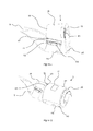
- Figure 1 shows a tanker aircraft 2 with a refuelling hose 1 in a deployed position, trailing behind the aircraft.
- the refuelling hose 1 is flexible and is mounted on a reel assembly within the tanker aircraft 2 so that operation of the reel assembly will deploy and retract the refuelling hose 1.
- the distal end 3 of the refuelling hose 1 comprises a valve connector 4 that mates with a probe 5 on the receiving aircraft 6 and a drogue 7 that provides a stabilising aerodynamic force.
- the drag created by the drogue 7 as the tanker aircraft 2 moves through the air provides a backwards force that drags the distal end 3 of the refuelling hose 1 behind the tanker aircraft 2 and in a position and orientation that is suitable for mating with the receiving aircraft 6.
- the drogue 7 also helps reduce oscillations in the hose that would otherwise cause the distal end of the refuelling hose to move around.
- FIG. 2 shows the distal end 3 of the refuelling hose 1 without a drogue attachment.
- the distal end 3 comprises a mating connector 4 that provides the sealed mechanical connection between the hose 1 and the probe of the receiving aircraft.
- a user definable interface (UDI) module 11 is mounted to the distal end of the refuelling hose 1 so that the connector 4 protrudes from one end of the module 11.
- the UDI module 11 allows a user to configure the end of the refuelling hose 1 with different functionality for different applications as will become apparent from the description that follows below.
- a data and/or power transmission cable 9 is wound around and embedded into the refuelling hose and terminates in an end connector 10 that connects the cable 9 to the UDI module 11 via an intermediate collar 18 (see below).
- FIG 3 shows a perspective view of the refuelling hose 1 showing the cable 9 embedded within the refuelling hose 1.
- the hose 1 comprises an inner fuel carrying hose 12 and an outer protective sheath 13 as well as a reinforcing sheath 14 that provides both increased strength and protection against electrical charges such as lightning strikes (part of the outer protective sheath 13 is removed in Figure 3 for clarity and to enable the path of the cable 9 to be seen).
- the cable 9 is flat and flexible and comprises a plurality of conducting wires 15 to carry power, data or any other electrical signals.
- the cable 9 is wrapped helically around the inner fuel carrying hose 12 and the reinforcing sheath 14 and is then covered by the outer protective sheath 13 so that the cable 9 is located between the reinforcing sheath 14 and the outer protective sheath 13.
- the cable 9 may be embedded within the outer protective sheath 13.
- the wires 15 themselves may be of any type, for example 4AWL wires for carrying power, wires for carrying data and/or power and/or fibre optic cables.
- the wires 15 may be copper, aluminium or optical wave guides or other suitable conductors.
- the cable 9 should be configured to carry both power and/or data signals with a degree of flexibility so that the hose 1 and cable 9 can be used with a variety of UDI modules, as explained in more detail hereinafter.
- the flexible hose 1 During normal duty the flexible hose 1 is exposed to bending forces caused by winding the hose 1 on and off a storage reel on the tanker aircraft and also from turbulence during operation, as the hose moves around in the air.
- the cable 9 is embedded within the hose 1 so will also be subject to those bending forces and there is a need to protect the cable 9, particularly the wires 15, from fatigue stresses. Bending the hose 1 and the cable 9 will exert tensile stress on one side of the wires 15 and compressive stress on the opposite side. Also, the direction of bending will change during operation, resulting in fatigue stress effects. The bending and fatigue stresses can alter the conductive properties of the wires 15 and affect the performance of the cable 9, possibly even causing the wires 15 to fail.
- each wire is provided with low friction insulation, made from a fluoropolymer or thermoplastic material, and the insulated wires 15 are contained within a low friction sleeve 17, also made from a fluoropolymer or thermoplastic material. This allows the insulated wires 15 to move around within the sleeve 17.
- the low friction contact between the insulated wires 15 and the sleeve 17 allows the wires 15 to move around within the sleeve 17 to the position of least stress as the hose 1 bends, thereby reducing the bending and fatigue stresses induced in the power, signal and fibre optic wires 15.
- the outer surface of the sleeve 17 is treated to allow it to be bonded to the outer protective sheath 13 or reinforcing sheath 14 of the hose 1.
- the treatment process could be chemical etching, plasma arc or bespoke RF surface modification that allows adhesive to bond to the sleeve 17.
- EMI Electromagnetic Impulse
- An EMI may occur naturally, such as from a lightning strike or as a result of the systems themselves, for example a build up of static electricity or short circuits.
- EMI may be used intentionally as weapon and the systems of the aircraft and the refuelling apparatus need to be protected from any such attack.
- FIG 4 shows a termination collar 18 that is fixed to the distal end of the refuelling hose to provide an electrical terminal and connection between the cable 9 and the UDI module 11 (see Figure 5 ).
- the termination collar 18 is attached to the outer wall 13 (see Figure 3 ) of the refuelling hose 1 to securely and rigidly attach the termination collar 18 to the hose 1.
- the termination collar 18 comprises a ring portion 19 with an inner diameter that is larger than and extends around the inner refuelling hose 12 and the mechanical connector 4 without interfering with the function of these components.
- the termination collar 18 comprises an angled cut out 20 at the end of the termination collar 18 facing along the hose 1 towards the tanker aircraft.
- the cut out has a face 47 that extends perpendicularly to the helix path of the cable 9 such that the face 47 is at 90 degrees relative to the helix angle of the cable 9.
- the face 47 comprises an electrical connector 21 configured to receive the end 23 of the helically wound cable 9 and the sleeve 17 is adhered or bonded to the termination collar 18.
- the angled cut out 20 and the face 47 allow the end 23 of the cable 9 to be easily received in the connector 21 without having to flex the cable 9 or disturb the helical path.
- the angled cut out 20 extends from the face 47 at an angle that is closely matched to the helix angle of the cable 9 so that the termination collar 18 is shaped to allow the cable 9 to freely connect with the connector 21.
- the end 23 of the cable 9 may be removably or permanently attached to the connector 21 on the termination collar 18.
- the connector 21 may be a zero insertion force type connector with a clamping element to prevent disconnection.
- Conductors 24 are embedded within the ring portion 19 of the termination collar 18 to connect the electrical connector 21 on angled face 47 to an electrical terminal 25 on the distal end 26 of the termination collar 18, facing away from the tanker aircraft.
- the conductors 24 initially follow the helical path through the collar 18 but then turn so that they extend in an axial direction of the hose and terminate at the end face of the collar 18, which lies in a plane extending at right-angles to the longitudinal axis of the hose.
- the conductors 24 may be copper, aluminium or optical wave guides. In this way, when the cable 9 is attached to the electrical connector 21, the cable 9 is in electrical contact with the terminal 25 on the end face 26 of the termination collar 18, so that electrical connection can then be made to the UDI module 11, as explained below with reference to Figure 5 .
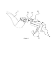
- FIG. 5 shows the distal end 3 of the refuelling hose 1 with the cable 9, termination collar 18 and the User Definable Interface (UDI) module 11 attached to the termination collar 18.
- the UDI module 11 and collar 18 are shown as being partially transparent for the purposes of clarity only.
- the UDI module 11 comprises two half-cylindrical portions or shells 27, 28 that are attachable to each other surrounding the refuelling hose 1.
- the UDI module 11 may also be attachable to the end 26 of the termination collar 18.
- the two parts 27, 28 of the UDI module 11 may be attachable to each other by a magnetic clamping system comprising a plurality of magnets, such as neodymium magnets, embedded in the mating faces of the two parts 27, 28.
- the magnets in each part 27, 28 have opposing poles such that they attract each other and clamp the two parts 27, 28 together.
- the magnets in one of the two parts 27, 28 are moveable so that the magnets can be moved from an aligned position for clamping to an unaligned positioned for separating the two parts 27, 28 of the UDI module 11.
- the magnets may be moveable by a manual lever or other actuator.
- the two parts 27, 28 of the UDI module are attachable by means of locking elements, fasteners, or any other suitable attachment that allows the UDI module 11 to be easily clamped and separated.
- the UDI module 11 may also be attached to the outer face 26 of the termination collar 18 by any of the attachment means described above.
- the UDI module 11 is easily removable from the refuelling hose 1 and can be changed during flight when the hose is retracted into the tanker aircraft 2.
- Different UDI modules 11 may be configured in different ways for different applications, for example refuelling of different aircraft or in different conditions.
- the UDI module 11 comprises an electrical connector 30 on the end face 31 of one of the half-cylindrical portions 27 that connects with the electrical terminal 25 on the end face 26 of the termination collar 18 to electrically connect the termination collar 18 to the UDI module 11.
- Conductors or wires 32 are embedded into, or mounted to, the UDI module 11 to connect any devices that are mounted in the UDI module 11 to the connector 30 and therefore to the tanker aircraft 2 via the cable 9.
- Some examples of components that the UDI module 11 may comprise are position sensors, accelerometers, pressure, temperature, flow rate sensors, connection sensors (to detect if the probe and hose are suitably mated) and so forth.
- the UDI module 11 is able to provide whatever functionality is required for each individual refuelling aircraft, or even each individual operation.
- the cable 9 provides the connectivity and the UDI module provides a platform for using any type of electrical equipment desired at the connection between the refuelling hose and the receiving aircraft.
- Figures 6a and 6b show the two portions 27, 28 of the UDI module 11 that are attachable to each other and to the end 26 of the termination collar 18.
- the UDI module 11 is fully configurable to change the connectivity and function of the refuelling hose 1 depending on the requirements of the user and the operation.
- Components such as sensors and connectors can be embedded within or attached to the UDI modules 11 and different UDI modules 11 can be provided for different applications.
- Each different UDI module 11 may utilise the wires 15 in the cable 9 differently so different connections will be required at the tanker end of the cable 9 as well.
- a user onboard the tanker aircraft 2 may change the UDI module 11 by removing the two portions 27, 28 and swapping them for a different UDI module 11, thereby changing the functionality and capabilities of the refuelling hose 1.
- Figure 7 shows an example configuration of the UDI module 11 without the body of the UDI module 11 showing, for purposes of clarity.
- the UDI module 11 comprises a power transfer unit 33, accelerometers 34 and heat and pressure sensors 35.
- the power transfer unit 33 is positioned on an outer face of the UDI module 11 and power is provided to the unit from the tanker aircraft 2 along the cable 9 in the refuelling hose 1.
- the receiving aircraft 2 will have a similar power transfer unit positioned on or near the probe 5 that connects with the refuelling hose 1 so that when the probe and the hose are connected, the two power transfer units are proximate to each other and power can be transferred from one aircraft to the other via induction.
- the accelerometers 34 can be used to determine the position and/or stability of the distal end 3 of the refuelling hose 1 which may be useful for informing the operators or systems about the condition of the connection or if the hose 1 is stable enough for a connection to be made in the first place. For example, high acceleration during fuel transfer may trigger the fuel transfer operation to be stopped as a safety precaution. Temperature and pressure sensors 35 in the UDI module 11 can inform operators or systems about the state of the fuel being transferred and therefore if the systems are working effectively or if there might be a blockage or other problem. Low or high temperatures caused by the high altitudes or malfunctioning systems may be dangerous so temperature sensors may be used to determine if fuel transfer is safe and inform an operator or system when the fuel temperature is outside a safe range.
- a further optional component for the UDI module 11 may include providing an electrical terminal (not shown) at the distal end 36 (see Figure 5 ) of the UDI module 11 that is configured to electrically connect to a connector on the receiving aircraft 6 when the refuelling connection is made.
- the receiving aircraft may comprise an electrical connector assembly either on, or near, the probe 5 that connects to the UDI module, allowing power and/or data to be transferred between the tanker aircraft 2 and the receiving aircraft 6 via the cable 9 in the refuelling hose 1.
- the connectors may magnetically orientate and/or lock together to ensure alignment before a connection is made.
- concentric slip rings may be used on the distal end of the UDI module that connect to a compatible slip ring arrangement on the receiving aircraft.
- the electrical connection along the hose 1 allows power and/or electrical signals to be carried from the tanker aircraft 2 to the receiving aircraft 6 and vice versa. Therefore, it is possible to provide power to the aircraft 6 being refuelled to recharge the batteries and extend the operating life of UAV's and AUAV's which carry limited life batteries. Furthermore, the tanker aircraft 2 is able to securely communicate with the receiving aircraft 6 to download data, such as surveillance images, or to upload instructions or perform diagnostic analysis on faulty or out of date systems. The data connection is more secure than a wireless alternative because it is direct, can not be intercepted and is protected from EMI and other such attacks.
- the UDI module 11 may be fitted with a drogue that functions in the conventional manner.
- the UDI module 11 may have aerodynamic control surfaces and an actuator to control the wings from the tanker aircraft 2 such that an operator onboard the tanker aircraft may control the attitude of the distal end of the refuelling hose 1 to facilitate the connection between the probe 5 and the distal end 3 of the hose 1.
- the UDI module 11 is changeable so a tanker aircraft will be able to switch between these applications during flight, depending on the requirements of each refuelling operation and the equipment onboard the receiving aircraft.
Landscapes
- Engineering & Computer Science (AREA)
- Mechanical Engineering (AREA)
- Power Engineering (AREA)
- Transportation (AREA)
- General Engineering & Computer Science (AREA)
- Sustainable Energy (AREA)
- Life Sciences & Earth Sciences (AREA)
- Sustainable Development (AREA)
- Aviation & Aerospace Engineering (AREA)
- Chemical & Material Sciences (AREA)
- Combustion & Propulsion (AREA)
- Microelectronics & Electronic Packaging (AREA)
- Rigid Pipes And Flexible Pipes (AREA)
Applications Claiming Priority (1)
| Application Number | Priority Date | Filing Date | Title |
|---|---|---|---|
| GB1205551.3A GB2500669B (en) | 2012-03-29 | 2012-03-29 | Hose for conveying fluid |
Publications (3)
| Publication Number | Publication Date |
|---|---|
| EP2644509A2 true EP2644509A2 (fr) | 2013-10-02 |
| EP2644509A3 EP2644509A3 (fr) | 2015-08-26 |
| EP2644509B1 EP2644509B1 (fr) | 2024-03-27 |
Family
ID=46087336
Family Applications (1)
| Application Number | Title | Priority Date | Filing Date |
|---|---|---|---|
| EP13156581.4A Active EP2644509B1 (fr) | 2012-03-29 | 2013-02-25 | Système de ravitaillement en vol |
Country Status (4)
| Country | Link |
|---|---|
| US (2) | US20130255986A1 (fr) |
| EP (1) | EP2644509B1 (fr) |
| ES (1) | ES2977454T3 (fr) |
| GB (1) | GB2500669B (fr) |
Cited By (6)
| Publication number | Priority date | Publication date | Assignee | Title |
|---|---|---|---|---|
| EP2876052A1 (fr) * | 2013-11-25 | 2015-05-27 | EADS Construcciones Aeronauticas S.A. | Tuyau flexible et système de ravitaillement en vol avec une commande de pression de carburant active |
| EP2915751A1 (fr) * | 2014-03-07 | 2015-09-09 | EADS Construcciones Aeronauticas S.A. | Procédé de ravitaillement en vol tuyau et panier et système avec une meilleure commande du mouvement tuyau et panier |
| WO2018108999A1 (fr) * | 2016-12-14 | 2018-06-21 | Polimer Kauçuk Sanayi Ve Pazarlama A.S. | Tuyau blindé électromagnétique comprenant une couche de signal pour guider un fluide |
| EP3418201A1 (fr) | 2017-06-22 | 2018-12-26 | Airbus Defence and Space SA | Système de rechargement électrique en vol |
| EP3584167A1 (fr) * | 2018-06-19 | 2019-12-25 | Airbus Defence and Space, S.A.U. | Tuyau de ravitaillement en vol et procédé de detection de dommages dans le tuyau de ravitaillement en vol |
| EP3564641A4 (fr) * | 2016-12-30 | 2020-08-05 | Beijing Goldwind Science & Creation Windpower Equipment Co., Ltd. | Connecteur électrique, dispositif d'essai d'état de fluide et système d'échange de chaleur de fluide |
Families Citing this family (53)
| Publication number | Priority date | Publication date | Assignee | Title |
|---|---|---|---|---|
| GB2500669B (en) | 2012-03-29 | 2016-03-30 | Icon Polymer Group | Hose for conveying fluid |
| US9843179B1 (en) * | 2013-04-16 | 2017-12-12 | The United States Of America As Represented By The Secretary Of The Navy | Corrosion resistant termination connector for steel wire rope/minesweeping cable |
| US10662625B2 (en) * | 2014-12-12 | 2020-05-26 | Delta Faucet Company | Sprayer hose assembly |
| CN104896206A (zh) * | 2015-05-13 | 2015-09-09 | 王丽 | 一种冷冻式干燥机气流送风管 |
| US10099799B2 (en) * | 2015-09-15 | 2018-10-16 | The Boeing Company | Articulated boom nozzle with torsion cable reel |
| GB2561524A (en) * | 2016-12-22 | 2018-10-24 | Linde Ag | A hose for connection to a gas cylinder |
| US11624326B2 (en) | 2017-05-21 | 2023-04-11 | Bj Energy Solutions, Llc | Methods and systems for supplying fuel to gas turbine engines |
| US11124314B2 (en) * | 2018-04-12 | 2021-09-21 | The Boeing Company | Systems and methods for transferring electric power to an aircraft during flight |
| US11545280B2 (en) | 2018-08-23 | 2023-01-03 | The Esab Group Inc. | Cable hose with embedded features |
| GB2574078B (en) * | 2018-09-27 | 2020-05-20 | pitman James | Methods and systems for in-flight fuelling of aircraft |
| US11560845B2 (en) | 2019-05-15 | 2023-01-24 | Bj Energy Solutions, Llc | Mobile gas turbine inlet air conditioning system and associated methods |
| CA3092859A1 (fr) | 2019-09-13 | 2021-03-13 | Bj Energy Solutions, Llc | Carburant, communications, systemes d`alimentation et methodes connexes |
| US10989180B2 (en) | 2019-09-13 | 2021-04-27 | Bj Energy Solutions, Llc | Power sources and transmission networks for auxiliary equipment onboard hydraulic fracturing units and associated methods |
| CA3191280A1 (fr) | 2019-09-13 | 2021-03-13 | Bj Energy Solutions, Llc | Methodes et systemes d`alimentation de turbines a gaz en carburant |
| US10895202B1 (en) | 2019-09-13 | 2021-01-19 | Bj Energy Solutions, Llc | Direct drive unit removal system and associated methods |
| US11015536B2 (en) | 2019-09-13 | 2021-05-25 | Bj Energy Solutions, Llc | Methods and systems for supplying fuel to gas turbine engines |
| US12065968B2 (en) | 2019-09-13 | 2024-08-20 | BJ Energy Solutions, Inc. | Systems and methods for hydraulic fracturing |
| US11015594B2 (en) | 2019-09-13 | 2021-05-25 | Bj Energy Solutions, Llc | Systems and method for use of single mass flywheel alongside torsional vibration damper assembly for single acting reciprocating pump |
| US10961914B1 (en) | 2019-09-13 | 2021-03-30 | BJ Energy Solutions, LLC Houston | Turbine engine exhaust duct system and methods for noise dampening and attenuation |
| US12338772B2 (en) | 2019-09-13 | 2025-06-24 | Bj Energy Solutions, Llc | Systems, assemblies, and methods to enhance intake air flow to a gas turbine engine of a hydraulic fracturing unit |
| CA3092863C (fr) | 2019-09-13 | 2023-07-18 | Bj Energy Solutions, Llc | Carburant, communications, systemes d`alimentation et methodes connexes |
| US11555756B2 (en) | 2019-09-13 | 2023-01-17 | Bj Energy Solutions, Llc | Fuel, communications, and power connection systems and related methods |
| US11002189B2 (en) | 2019-09-13 | 2021-05-11 | Bj Energy Solutions, Llc | Mobile gas turbine inlet air conditioning system and associated methods |
| US10815764B1 (en) | 2019-09-13 | 2020-10-27 | Bj Energy Solutions, Llc | Methods and systems for operating a fleet of pumps |
| CA3092865C (fr) | 2019-09-13 | 2023-07-04 | Bj Energy Solutions, Llc | Sources d`alimentation et reseaux de transmission pour du materiel auxiliaire a bord d`unites de fracturation hydraulique et methodes connexes |
| US11708829B2 (en) | 2020-05-12 | 2023-07-25 | Bj Energy Solutions, Llc | Cover for fluid systems and related methods |
| US10968837B1 (en) | 2020-05-14 | 2021-04-06 | Bj Energy Solutions, Llc | Systems and methods utilizing turbine compressor discharge for hydrostatic manifold purge |
| US11428165B2 (en) | 2020-05-15 | 2022-08-30 | Bj Energy Solutions, Llc | Onboard heater of auxiliary systems using exhaust gases and associated methods |
| US11208880B2 (en) | 2020-05-28 | 2021-12-28 | Bj Energy Solutions, Llc | Bi-fuel reciprocating engine to power direct drive turbine fracturing pumps onboard auxiliary systems and related methods |
| US11208953B1 (en) | 2020-06-05 | 2021-12-28 | Bj Energy Solutions, Llc | Systems and methods to enhance intake air flow to a gas turbine engine of a hydraulic fracturing unit |
| US11109508B1 (en) | 2020-06-05 | 2021-08-31 | Bj Energy Solutions, Llc | Enclosure assembly for enhanced cooling of direct drive unit and related methods |
| US10961908B1 (en) | 2020-06-05 | 2021-03-30 | Bj Energy Solutions, Llc | Systems and methods to enhance intake air flow to a gas turbine engine of a hydraulic fracturing unit |
| US11111768B1 (en) | 2020-06-09 | 2021-09-07 | Bj Energy Solutions, Llc | Drive equipment and methods for mobile fracturing transportation platforms |
| US11066915B1 (en) | 2020-06-09 | 2021-07-20 | Bj Energy Solutions, Llc | Methods for detection and mitigation of well screen out |
| US11022526B1 (en) | 2020-06-09 | 2021-06-01 | Bj Energy Solutions, Llc | Systems and methods for monitoring a condition of a fracturing component section of a hydraulic fracturing unit |
| US10954770B1 (en) | 2020-06-09 | 2021-03-23 | Bj Energy Solutions, Llc | Systems and methods for exchanging fracturing components of a hydraulic fracturing unit |
| US11933153B2 (en) | 2020-06-22 | 2024-03-19 | Bj Energy Solutions, Llc | Systems and methods to operate hydraulic fracturing units using automatic flow rate and/or pressure control |
| US11939853B2 (en) | 2020-06-22 | 2024-03-26 | Bj Energy Solutions, Llc | Systems and methods providing a configurable staged rate increase function to operate hydraulic fracturing units |
| US11028677B1 (en) | 2020-06-22 | 2021-06-08 | Bj Energy Solutions, Llc | Stage profiles for operations of hydraulic systems and associated methods |
| US11125066B1 (en) | 2020-06-22 | 2021-09-21 | Bj Energy Solutions, Llc | Systems and methods to operate a dual-shaft gas turbine engine for hydraulic fracturing |
| US11473413B2 (en) | 2020-06-23 | 2022-10-18 | Bj Energy Solutions, Llc | Systems and methods to autonomously operate hydraulic fracturing units |
| US11466680B2 (en) | 2020-06-23 | 2022-10-11 | Bj Energy Solutions, Llc | Systems and methods of utilization of a hydraulic fracturing unit profile to operate hydraulic fracturing units |
| US11220895B1 (en) | 2020-06-24 | 2022-01-11 | Bj Energy Solutions, Llc | Automated diagnostics of electronic instrumentation in a system for fracturing a well and associated methods |
| US11149533B1 (en) | 2020-06-24 | 2021-10-19 | Bj Energy Solutions, Llc | Systems to monitor, detect, and/or intervene relative to cavitation and pulsation events during a hydraulic fracturing operation |
| US11193361B1 (en) | 2020-07-17 | 2021-12-07 | Bj Energy Solutions, Llc | Methods, systems, and devices to enhance fracturing fluid delivery to subsurface formations during high-pressure fracturing operations |
| CN111942188B (zh) * | 2020-08-11 | 2022-04-12 | 北京京东乾石科技有限公司 | 一种无人机空中充电系统、充电方法、装置、设备和介质 |
| RU2748810C1 (ru) * | 2020-10-16 | 2021-05-31 | Акционерное общество "Научно-производственное предприятие "Звезда" имени академика Г.И. Северина" | Топливный шланг агрегата заправки топливом в полете |
| RU203665U1 (ru) * | 2020-12-04 | 2021-04-15 | Акционерное общество "Научно-производственное предприятие "Звезда" имени академика Г.И. Северина" | Топливный шланг агрегата заправки топливом в полете |
| RU2749470C1 (ru) * | 2020-12-04 | 2021-06-11 | Акционерное общество "Научно-производственное предприятие "Звезда" имени академика Г.И. Северина" | Топливный шланг агрегата заправки топливом в полете |
| US11639654B2 (en) | 2021-05-24 | 2023-05-02 | Bj Energy Solutions, Llc | Hydraulic fracturing pumps to enhance flow of fracturing fluid into wellheads and related methods |
| US12378864B2 (en) | 2021-10-25 | 2025-08-05 | Bj Energy Solutions, Llc | Systems and methods to reduce acoustic resonance or disrupt standing wave formation in a fluid manifold of a high-pressure fracturing system |
| GB2620987A (en) * | 2022-07-29 | 2024-01-31 | Baker Hughes Energy Technology UK Ltd | Pipe cable assembly |
| EP4545420A1 (fr) * | 2023-10-24 | 2025-04-30 | Airbus Defence and Space, S.A.U. | Tuyau de ravitaillement air-air |
Family Cites Families (88)
| Publication number | Priority date | Publication date | Assignee | Title |
|---|---|---|---|---|
| US482181A (en) * | 1892-09-06 | Electric connector for hose | ||
| US2438146A (en) * | 1945-06-07 | 1948-03-23 | American Brass Co | Flexible metal hose |
| US2663523A (en) * | 1949-08-02 | 1953-12-22 | Boeing Co | Aircraft interconnecting mechanism |
| US2949265A (en) * | 1954-03-22 | 1960-08-16 | Boeing Co | Articulated aircraft refueling boom |
| US2973163A (en) * | 1956-02-03 | 1961-02-28 | Flight Refueling Inc | Apparatus for trailing a fluid-transmitting hose or tow-line from an aircraft |
| US3023267A (en) * | 1959-03-05 | 1962-02-27 | Gen Cable Corp | Combination power and communication cable |
| US3034085A (en) * | 1959-12-09 | 1962-05-08 | Whirlpool Co | Combined fluid and electrical connector |
| NL273812A (fr) * | 1961-02-27 | |||
| US3285544A (en) * | 1964-02-26 | 1966-11-15 | Industrial Nucleonics Corp | Mid-air refueling system |
| US3387319A (en) * | 1965-06-28 | 1968-06-11 | Electrolux Corp | Airflow-electric coupling for vacuum cleaner |
| DE1750392A1 (de) * | 1968-04-11 | 1970-11-12 | Gossler Kg Oscar | Vorrichtung zum Anschluss einer elektrischen Leitung an einen Schlauch |
| IT957531B (it) * | 1971-03-10 | 1973-10-20 | Dornier Ag | Fune d ormeggio per aerodine |
| US3780208A (en) * | 1972-06-05 | 1973-12-18 | Moore & Co Samuel | Composite hose having a grounding wire enclosed in a sleeve and wrapped about the core tube of the hose |
| NL7414546A (nl) * | 1973-11-15 | 1975-05-20 | Rhone Poulenc Sa | Soepele verwarmingsbuis en werkwijze voor het vervaardigen ervan. |
| SE7401692L (fr) * | 1974-02-08 | 1975-08-11 | Electrolux Ab | |
| US4059847A (en) * | 1976-09-01 | 1977-11-22 | Dayco Corporation | Hose having an electrically conductive layer for dissipating static electricity and method of making same |
| US4063790A (en) * | 1976-10-15 | 1977-12-20 | Dayco Corporation | Fluid conduit assembly |
| US4108701A (en) * | 1977-06-01 | 1978-08-22 | The Goodyear Tire & Rubber Company | Method for making hose incorporating an embedded static ground conductor |
| US4129270A (en) * | 1977-06-13 | 1978-12-12 | The Boeing Company | Air refueling boom pivot gimbal arrangements |
| US4162370A (en) * | 1977-06-24 | 1979-07-24 | Automation Industries, Inc. | Current carrying hose assembly |
| US4167645A (en) * | 1977-11-14 | 1979-09-11 | Dayco Corporation | Electrical current-carrying fluid hose construction |
| US4196464A (en) * | 1978-02-23 | 1980-04-01 | Eaton Corporation | Semi-conductive layer-containing reinforced pressure hose and method of making same |
| US4462649A (en) * | 1980-05-05 | 1984-07-31 | Dayco Corporation | Hose construction and method of making same |
| US4405969A (en) * | 1981-10-02 | 1983-09-20 | The Polymer Corporation | Anti-static hose assemblies |
| US4964692A (en) * | 1982-07-21 | 1990-10-23 | Smith & Nephew Dyonics, Inc. | Fiber bundle illumination system |
| JPS617809U (ja) * | 1984-06-19 | 1986-01-17 | 住友電気工業株式会社 | シ−ルド電線 |
| GB8431067D0 (en) * | 1984-12-08 | 1985-01-16 | British Aerospace | Cable conduit system for vehicles |
| USH297H (en) * | 1985-08-12 | 1987-07-07 | The United States Of America As Represented By The Secretary Of The Air Force | Robotic refueling system for tactical and strategic aircraft |
| US4815816A (en) * | 1987-05-12 | 1989-03-28 | Rts Laboratories, Inc. | Image transportation device using incoherent fiber optics bundles and method of using same |
| JPH0416045Y2 (fr) * | 1987-11-16 | 1992-04-10 | ||
| FR2659437B1 (fr) * | 1990-03-07 | 1994-03-25 | Caoutchouc Manufacture Plastique | Moyen de reperage lineaire de longueur, de vitesse ou de positionnement pour article souple de grande longeur. |
| FR2662229B1 (fr) * | 1990-05-17 | 1992-07-31 | Coflexip | Conduite tubulaire flexible comportant des moyens de chauffage incorpores. |
| US5102012A (en) * | 1990-08-31 | 1992-04-07 | Dayco Products, Inc. | Fuel dispensing system having a flexible hose with a static dissipater and a fuel leak detector |
| US5220130A (en) * | 1991-08-06 | 1993-06-15 | Cooper Industries, Inc. | Dual insulated data cable |
| US5170011A (en) * | 1991-09-25 | 1992-12-08 | Teleflex Incorporated | Hose assembly |
| FR2714708B1 (fr) * | 1994-01-05 | 1996-03-08 | Giat Ind Sa | Conduite tubulaire flexible comportant un câble de transmission d'information. |
| US5600752A (en) * | 1994-03-11 | 1997-02-04 | Industrial Design Laboratories, Inc. | Flexible gas hose assembly with concentric helical tube members having reinforcement spring coils |
| US5573206A (en) * | 1994-08-19 | 1996-11-12 | Able Corporation | Hose and drogue boom refueling system, for aircraft |
| US5539624A (en) * | 1995-01-17 | 1996-07-23 | Durodyne, Inc. | Illuminated hose |
| US5921285A (en) * | 1995-09-28 | 1999-07-13 | Fiberspar Spoolable Products, Inc. | Composite spoolable tube |
| US7498509B2 (en) * | 1995-09-28 | 2009-03-03 | Fiberspar Corporation | Composite coiled tubing end connector |
| CA2163702C (fr) * | 1995-11-24 | 2000-05-30 | Mark Beauchamp | Cable electrique resistant aux flammes |
| US6441308B1 (en) * | 1996-06-07 | 2002-08-27 | Cable Design Technologies, Inc. | Cable with dual layer jacket |
| US6061490A (en) * | 1997-08-01 | 2000-05-09 | Mitsubishi Rayon Co., Ltd. | Optical fiber bundle with bundling member |
| US6114632A (en) * | 1998-03-05 | 2000-09-05 | Planas, Sr.; Alberto E. | Integrated power and data communication hybrid cable assembly for local area computer network |
| GB2345199B (en) * | 1998-12-22 | 2003-06-04 | Philip Head | Tubing and conductors or conduits |
| CA2381423C (fr) * | 1999-09-07 | 2009-04-07 | Utilx Corporation | Cable contenant un ecoulement |
| US6445576B1 (en) * | 2000-02-25 | 2002-09-03 | Intel Corporation | Tilt mounted hard drive bay |
| US6604711B1 (en) * | 2000-11-20 | 2003-08-12 | Sargent Fletcher, Inc. | Autonomous system for the aerial refueling or decontamination of unmanned airborne vehicles |
| US6901191B2 (en) * | 2001-11-12 | 2005-05-31 | Corning Cable Systems Llc | High density fiber optic cable |
| US6710243B2 (en) * | 2002-06-27 | 2004-03-23 | Capativa Tech, Inc. | Structure of signal line |
| US6786455B1 (en) * | 2002-09-05 | 2004-09-07 | Asher Bartov | Method for engaging a probe and drogue for aerial refueling |
| US7152828B1 (en) * | 2002-11-01 | 2006-12-26 | Sargent Fletcher, Inc. | Method and apparatus for the hookup of unmanned/manned (“hum”) multi purpose vehicles with each other |
| US7041935B2 (en) * | 2002-11-12 | 2006-05-09 | Thermal Dynamics Corporation | Apparatus and methods for connecting a plasma arc torch lead to a power supply |
| US6811427B2 (en) * | 2002-11-15 | 2004-11-02 | Western Digital Technologies, Inc. | Robust serial advanced technology attachment (SATA) cable connector |
| NO324787B1 (no) * | 2003-06-16 | 2007-12-10 | Aker Subsea As | Undersjøisk kontrollkabel/produksjonsledning |
| US7226302B2 (en) * | 2003-09-22 | 2007-06-05 | Scotech Systems Inc. | Vacuum cleaner current-carrying hose connection system |
| US7837151B1 (en) * | 2003-11-01 | 2010-11-23 | Sargent Fletcher, Inc. | Method and apparatus for the hookup of unmanned/manned (“HUM”) multi purpose air vehicles with each other |
| WO2005047748A1 (fr) * | 2003-11-12 | 2005-05-26 | Huber+Suhner Ag | Tuyau servant a acheminer des milieux, en particulier pulverulents, generateurs de charges electrostatiques |
| US7313000B2 (en) * | 2003-12-05 | 2007-12-25 | Ultra Products, Inc. | Power distribution system for a personal computer |
| US7185854B2 (en) * | 2004-06-18 | 2007-03-06 | The Boeing Company | In-flight refueling system and method for extending and retracting an in-flight refueling device |
| US7281687B2 (en) * | 2004-07-14 | 2007-10-16 | The Boeing Company | In-flight refueling system and method for facilitating emergency separation of in-flight refueling system components |
| US7097139B2 (en) * | 2004-07-22 | 2006-08-29 | The Boeing Company | In-flight refueling system, damping device and method for damping oscillations in in-flight refueling system components |
| US7137598B2 (en) * | 2004-08-26 | 2006-11-21 | The Boeing Company | In-flight refueling system, sensor system and method for damping oscillations in in-flight refueling system components |
| US7637458B2 (en) * | 2005-06-08 | 2009-12-29 | The Boeing Company | Systems and methods for providing back-up hydraulic power for aircraft, including tanker aircraft |
| US7219857B2 (en) * | 2005-06-20 | 2007-05-22 | The Boeing Company | Controllable refueling drogues and associated systems and methods |
| US7172444B1 (en) * | 2005-07-28 | 2007-02-06 | Jui-Shu Huang | Hard drive contact pin connector device |
| FR2903475B1 (fr) * | 2006-07-05 | 2011-10-21 | Sofanou Sa | Gaine tubulaire annelee de protection comprenant une charniere et dispositif pour fabriquer une telle gaine |
| ITMI20061436A1 (it) * | 2006-07-21 | 2008-01-22 | Colbachini Spa | Tubo flessibile ondulato di tipo perfezionato,con cavo elettrico incorporato. |
| GB2443671B (en) * | 2006-11-13 | 2011-03-09 | Steven Martin Hudson | Data transmission between electro-statically charged bodies |
| US20080250632A1 (en) * | 2007-02-12 | 2008-10-16 | Dayton Douglas C | System and method of a conformable cable |
| US7900866B2 (en) * | 2007-10-18 | 2011-03-08 | The Boeing Company | System and methods for airborne launch and recovery of aircraft |
| US8231083B2 (en) * | 2007-10-18 | 2012-07-31 | The Boeing Company | System and methods for airborne launch and recovery of aircraft |
| US8332081B2 (en) * | 2008-05-22 | 2012-12-11 | Eads Construcciones Aeronauticas, S.A. | Methods and systems for reducing the phenomenon of structural coupling in the control system of an in-flight refuelling boom |
| US7887358B2 (en) * | 2008-07-08 | 2011-02-15 | Adtron Corporation | Connector clamp |
| JP5197300B2 (ja) * | 2008-10-21 | 2013-05-15 | 株式会社マキタ | コード付きホース及び集塵機 |
| JP5592394B2 (ja) * | 2008-12-17 | 2014-09-17 | ザ・ボーイング・カンパニー | 燃料補給ブームに掛かる力の自動的軽減 |
| DE102009022796B4 (de) * | 2009-05-27 | 2015-12-03 | Airbus Operations Gmbh | Vorrichtung zum Verlegen eines in einem Flugzeug installierten Kabelstrangs |
| US8220746B1 (en) * | 2009-05-29 | 2012-07-17 | The Boeing Company | Broad speed range inflatable drogue canopy |
| BR112012003882A2 (pt) * | 2009-08-21 | 2016-03-29 | Titeflex Corp | tubo dissipador de energia, métodos de fabricação de tubulação dissipadora de energia, método de instalação e dispositivos de vedação de um tubo dissipador de energia |
| US8083536B2 (en) * | 2009-08-31 | 2011-12-27 | Ocz Technology Group Inc | Connector assembly and method for SATA drives |
| US8763955B1 (en) * | 2009-08-31 | 2014-07-01 | The Boeing Company | Method and apparatus for controlling a refueling drogue |
| US7972167B2 (en) * | 2009-09-14 | 2011-07-05 | Better Place GmbH | Electrical connector with a flexible blade-shaped housing with a handle with an opening |
| JP5679553B2 (ja) * | 2010-11-24 | 2015-03-04 | 矢崎総業株式会社 | ワイヤハーネス |
| US20120160536A1 (en) * | 2010-12-23 | 2012-06-28 | Mike Beining | Fluid connector with hose cutting ring |
| US20130037323A1 (en) * | 2011-08-12 | 2013-02-14 | Jaime Smith | Electroluminescent systems |
| US9457912B2 (en) * | 2012-01-04 | 2016-10-04 | Israel Aerospace Industries Ltd. | Systems and methods for air vehicles |
| GB2500669B (en) | 2012-03-29 | 2016-03-30 | Icon Polymer Group | Hose for conveying fluid |
-
2012
- 2012-03-29 GB GB1205551.3A patent/GB2500669B/en active Active
-
2013
- 2013-02-25 ES ES13156581T patent/ES2977454T3/es active Active
- 2013-02-25 EP EP13156581.4A patent/EP2644509B1/fr active Active
- 2013-03-22 US US13/848,753 patent/US20130255986A1/en not_active Abandoned
-
2016
- 2016-09-28 US US15/278,071 patent/US10267439B2/en active Active
Non-Patent Citations (1)
| Title |
|---|
| None |
Cited By (9)
| Publication number | Priority date | Publication date | Assignee | Title |
|---|---|---|---|---|
| EP2876052A1 (fr) * | 2013-11-25 | 2015-05-27 | EADS Construcciones Aeronauticas S.A. | Tuyau flexible et système de ravitaillement en vol avec une commande de pression de carburant active |
| EP2915751A1 (fr) * | 2014-03-07 | 2015-09-09 | EADS Construcciones Aeronauticas S.A. | Procédé de ravitaillement en vol tuyau et panier et système avec une meilleure commande du mouvement tuyau et panier |
| US9969502B2 (en) | 2014-03-07 | 2018-05-15 | Eads Construcciones Aeronauticas S.A. | In-flight refueling method and system for controlling motion of the hose and drogue |
| WO2018108999A1 (fr) * | 2016-12-14 | 2018-06-21 | Polimer Kauçuk Sanayi Ve Pazarlama A.S. | Tuyau blindé électromagnétique comprenant une couche de signal pour guider un fluide |
| GB2557648A (en) * | 2016-12-14 | 2018-06-27 | Polimer Kaucuk Sanayi Ve Pazarlama A S | Hose for guiding a fluid |
| EP3564641A4 (fr) * | 2016-12-30 | 2020-08-05 | Beijing Goldwind Science & Creation Windpower Equipment Co., Ltd. | Connecteur électrique, dispositif d'essai d'état de fluide et système d'échange de chaleur de fluide |
| EP3418201A1 (fr) | 2017-06-22 | 2018-12-26 | Airbus Defence and Space SA | Système de rechargement électrique en vol |
| EP3584167A1 (fr) * | 2018-06-19 | 2019-12-25 | Airbus Defence and Space, S.A.U. | Tuyau de ravitaillement en vol et procédé de detection de dommages dans le tuyau de ravitaillement en vol |
| US10996136B2 (en) | 2018-06-19 | 2021-05-04 | Airbus Defence And Space, S.A.U. | Air to air refueling hose and method for detecting damage in air to air refueling hose |
Also Published As
| Publication number | Publication date |
|---|---|
| GB201205551D0 (en) | 2012-05-09 |
| GB2500669B (en) | 2016-03-30 |
| EP2644509A3 (fr) | 2015-08-26 |
| EP2644509B1 (fr) | 2024-03-27 |
| US20130255986A1 (en) | 2013-10-03 |
| US20170241576A1 (en) | 2017-08-24 |
| ES2977454T3 (es) | 2024-08-23 |
| US10267439B2 (en) | 2019-04-23 |
| GB2500669A (en) | 2013-10-02 |
Similar Documents
| Publication | Publication Date | Title |
|---|---|---|
| US10267439B2 (en) | Hose for conveying fluid | |
| US7185854B2 (en) | In-flight refueling system and method for extending and retracting an in-flight refueling device | |
| US9716374B2 (en) | Systems and methods for electrical harness construction | |
| US20200010193A1 (en) | Method and Apparatus for Unmanned Aerial Maritime Float Vehicle That Sense and Report Relevant Data from Physical and Operational Environment | |
| US20120168168A1 (en) | System and method for connection and installation of underwater lines | |
| EP2774838A2 (fr) | Avion autonome | |
| EP2835313B1 (fr) | Sonde de ravitaillement polyvalente | |
| EP2759478B1 (fr) | Pointe avec buse de détection de charge et fonctionnalité de communication sans fil pour perche de ravitaillement | |
| EP2738097B1 (fr) | Systèmes de ravitaillement en vol avec un sous-système de communication digital | |
| US20120168567A1 (en) | Electrical power transfer assembly | |
| US10099799B2 (en) | Articulated boom nozzle with torsion cable reel | |
| US6786455B1 (en) | Method for engaging a probe and drogue for aerial refueling | |
| EP2531695B1 (fr) | Câble et procédé d'acheminement et de connexion d'un signal pouvant être traité en différé | |
| EP3870510B1 (fr) | Ensemble formant tuyau souple de carburant pour ravitaillement de carburant en vol d'aéronef | |
| WO2013114138A2 (fr) | Déploiement amélioré d'installations sous-marines | |
| WO2020104766A1 (fr) | Récupération d'un véhicule sans pilote | |
| EP2370317B1 (fr) | Atténuation automatique des forces s'exerçant sur une perche de ravitaillement | |
| EP3221933B1 (fr) | Ensemble sortie de câble automatique et procédé | |
| EP2528820B1 (fr) | Systeme de réglage d'un treuil pour perche de ravitaillement en vol | |
| EP4667363A1 (fr) | Système de stabilisation et de guidage d'ensemble de cône de ravitaillement aérien | |
| WO2012080207A1 (fr) | Câble et système pour la transmission de signaux optiques et électriques | |
| RU2784626C1 (ru) | Способ передачи электрических сигналов из электросистемы пусковой установки в электросистему отделяемого объекта | |
| CN223142188U (zh) | 静电释放系统及交通工具 | |
| CN215155708U (zh) | 旋翼式垂直起降无人机线束结构 | |
| WO2006081820A1 (fr) | Mecanisme de decouplage pour raccords male et femelle |
Legal Events
| Date | Code | Title | Description |
|---|---|---|---|
| PUAI | Public reference made under article 153(3) epc to a published international application that has entered the european phase |
Free format text: ORIGINAL CODE: 0009012 |
|
| AK | Designated contracting states |
Kind code of ref document: A2 Designated state(s): AL AT BE BG CH CY CZ DE DK EE ES FI FR GB GR HR HU IE IS IT LI LT LU LV MC MK MT NL NO PL PT RO RS SE SI SK SM TR |
|
| AX | Request for extension of the european patent |
Extension state: BA ME |
|
| PUAL | Search report despatched |
Free format text: ORIGINAL CODE: 0009013 |
|
| AK | Designated contracting states |
Kind code of ref document: A3 Designated state(s): AL AT BE BG CH CY CZ DE DK EE ES FI FR GB GR HR HU IE IS IT LI LT LU LV MC MK MT NL NO PL PT RO RS SE SI SK SM TR |
|
| AX | Request for extension of the european patent |
Extension state: BA ME |
|
| RIC1 | Information provided on ipc code assigned before grant |
Ipc: B64D 39/00 20060101AFI20150723BHEP |
|
| 17P | Request for examination filed |
Effective date: 20160601 |
|
| RBV | Designated contracting states (corrected) |
Designated state(s): AL AT BE BG CH CY CZ DE DK EE ES FI FR GB GR HR HU IE IS IT LI LT LU LV MC MK MT NL NO PL PT RO RS SE SI SK SM TR |
|
| STAA | Information on the status of an ep patent application or granted ep patent |
Free format text: STATUS: EXAMINATION IS IN PROGRESS |
|
| 17Q | First examination report despatched |
Effective date: 20181116 |
|
| 19U | Interruption of proceedings before grant |
Effective date: 20181218 |
|
| 19W | Proceedings resumed before grant after interruption of proceedings |
Effective date: 20200302 |
|
| RAP1 | Party data changed (applicant data changed or rights of an application transferred) |
Owner name: CROSSLINK TECHNOLOGY HOLDINGS LIMITED |
|
| GRAP | Despatch of communication of intention to grant a patent |
Free format text: ORIGINAL CODE: EPIDOSNIGR1 |
|
| STAA | Information on the status of an ep patent application or granted ep patent |
Free format text: STATUS: GRANT OF PATENT IS INTENDED |
|
| INTG | Intention to grant announced |
Effective date: 20230515 |
|
| GRAS | Grant fee paid |
Free format text: ORIGINAL CODE: EPIDOSNIGR3 |
|
| GRAA | (expected) grant |
Free format text: ORIGINAL CODE: 0009210 |
|
| STAA | Information on the status of an ep patent application or granted ep patent |
Free format text: STATUS: THE PATENT HAS BEEN GRANTED |
|
| AK | Designated contracting states |
Kind code of ref document: B1 Designated state(s): AL AT BE BG CH CY CZ DE DK EE ES FI FR GB GR HR HU IE IS IT LI LT LU LV MC MK MT NL NO PL PT RO RS SE SI SK SM TR |
|
| REG | Reference to a national code |
Ref country code: GB Ref legal event code: FG4D |
|
| REG | Reference to a national code |
Ref country code: CH Ref legal event code: EP |
|
| REG | Reference to a national code |
Ref country code: DE Ref legal event code: R096 Ref document number: 602013085486 Country of ref document: DE |
|
| REG | Reference to a national code |
Ref country code: IE Ref legal event code: FG4D |
|
| PG25 | Lapsed in a contracting state [announced via postgrant information from national office to epo] |
Ref country code: LT Free format text: LAPSE BECAUSE OF FAILURE TO SUBMIT A TRANSLATION OF THE DESCRIPTION OR TO PAY THE FEE WITHIN THE PRESCRIBED TIME-LIMIT Effective date: 20240327 |
|
| REG | Reference to a national code |
Ref country code: LT Ref legal event code: MG9D |
|
| PG25 | Lapsed in a contracting state [announced via postgrant information from national office to epo] |
Ref country code: GR Free format text: LAPSE BECAUSE OF FAILURE TO SUBMIT A TRANSLATION OF THE DESCRIPTION OR TO PAY THE FEE WITHIN THE PRESCRIBED TIME-LIMIT Effective date: 20240628 |
|
| PG25 | Lapsed in a contracting state [announced via postgrant information from national office to epo] |
Ref country code: RS Free format text: LAPSE BECAUSE OF FAILURE TO SUBMIT A TRANSLATION OF THE DESCRIPTION OR TO PAY THE FEE WITHIN THE PRESCRIBED TIME-LIMIT Effective date: 20240627 Ref country code: HR Free format text: LAPSE BECAUSE OF FAILURE TO SUBMIT A TRANSLATION OF THE DESCRIPTION OR TO PAY THE FEE WITHIN THE PRESCRIBED TIME-LIMIT Effective date: 20240327 |
|
| PG25 | Lapsed in a contracting state [announced via postgrant information from national office to epo] |
Ref country code: RS Free format text: LAPSE BECAUSE OF FAILURE TO SUBMIT A TRANSLATION OF THE DESCRIPTION OR TO PAY THE FEE WITHIN THE PRESCRIBED TIME-LIMIT Effective date: 20240627 Ref country code: NO Free format text: LAPSE BECAUSE OF FAILURE TO SUBMIT A TRANSLATION OF THE DESCRIPTION OR TO PAY THE FEE WITHIN THE PRESCRIBED TIME-LIMIT Effective date: 20240627 Ref country code: LT Free format text: LAPSE BECAUSE OF FAILURE TO SUBMIT A TRANSLATION OF THE DESCRIPTION OR TO PAY THE FEE WITHIN THE PRESCRIBED TIME-LIMIT Effective date: 20240327 Ref country code: HR Free format text: LAPSE BECAUSE OF FAILURE TO SUBMIT A TRANSLATION OF THE DESCRIPTION OR TO PAY THE FEE WITHIN THE PRESCRIBED TIME-LIMIT Effective date: 20240327 Ref country code: GR Free format text: LAPSE BECAUSE OF FAILURE TO SUBMIT A TRANSLATION OF THE DESCRIPTION OR TO PAY THE FEE WITHIN THE PRESCRIBED TIME-LIMIT Effective date: 20240628 Ref country code: FI Free format text: LAPSE BECAUSE OF FAILURE TO SUBMIT A TRANSLATION OF THE DESCRIPTION OR TO PAY THE FEE WITHIN THE PRESCRIBED TIME-LIMIT Effective date: 20240327 Ref country code: BG Free format text: LAPSE BECAUSE OF FAILURE TO SUBMIT A TRANSLATION OF THE DESCRIPTION OR TO PAY THE FEE WITHIN THE PRESCRIBED TIME-LIMIT Effective date: 20240327 |
|
| REG | Reference to a national code |
Ref country code: NL Ref legal event code: MP Effective date: 20240327 |
|
| REG | Reference to a national code |
Ref country code: ES Ref legal event code: FG2A Ref document number: 2977454 Country of ref document: ES Kind code of ref document: T3 Effective date: 20240823 |
|
| PG25 | Lapsed in a contracting state [announced via postgrant information from national office to epo] |
Ref country code: SE Free format text: LAPSE BECAUSE OF FAILURE TO SUBMIT A TRANSLATION OF THE DESCRIPTION OR TO PAY THE FEE WITHIN THE PRESCRIBED TIME-LIMIT Effective date: 20240327 Ref country code: LV Free format text: LAPSE BECAUSE OF FAILURE TO SUBMIT A TRANSLATION OF THE DESCRIPTION OR TO PAY THE FEE WITHIN THE PRESCRIBED TIME-LIMIT Effective date: 20240327 |
|
| PG25 | Lapsed in a contracting state [announced via postgrant information from national office to epo] |
Ref country code: NL Free format text: LAPSE BECAUSE OF FAILURE TO SUBMIT A TRANSLATION OF THE DESCRIPTION OR TO PAY THE FEE WITHIN THE PRESCRIBED TIME-LIMIT Effective date: 20240327 |
|
| REG | Reference to a national code |
Ref country code: AT Ref legal event code: MK05 Ref document number: 1669699 Country of ref document: AT Kind code of ref document: T Effective date: 20240327 |
|
| PG25 | Lapsed in a contracting state [announced via postgrant information from national office to epo] |
Ref country code: NL Free format text: LAPSE BECAUSE OF FAILURE TO SUBMIT A TRANSLATION OF THE DESCRIPTION OR TO PAY THE FEE WITHIN THE PRESCRIBED TIME-LIMIT Effective date: 20240327 |
|
| PG25 | Lapsed in a contracting state [announced via postgrant information from national office to epo] |
Ref country code: IS Free format text: LAPSE BECAUSE OF FAILURE TO SUBMIT A TRANSLATION OF THE DESCRIPTION OR TO PAY THE FEE WITHIN THE PRESCRIBED TIME-LIMIT Effective date: 20240727 |
|
| PG25 | Lapsed in a contracting state [announced via postgrant information from national office to epo] |
Ref country code: PT Free format text: LAPSE BECAUSE OF FAILURE TO SUBMIT A TRANSLATION OF THE DESCRIPTION OR TO PAY THE FEE WITHIN THE PRESCRIBED TIME-LIMIT Effective date: 20240729 Ref country code: SM Free format text: LAPSE BECAUSE OF FAILURE TO SUBMIT A TRANSLATION OF THE DESCRIPTION OR TO PAY THE FEE WITHIN THE PRESCRIBED TIME-LIMIT Effective date: 20240327 |
|
| PG25 | Lapsed in a contracting state [announced via postgrant information from national office to epo] |
Ref country code: EE Free format text: LAPSE BECAUSE OF FAILURE TO SUBMIT A TRANSLATION OF THE DESCRIPTION OR TO PAY THE FEE WITHIN THE PRESCRIBED TIME-LIMIT Effective date: 20240327 Ref country code: CZ Free format text: LAPSE BECAUSE OF FAILURE TO SUBMIT A TRANSLATION OF THE DESCRIPTION OR TO PAY THE FEE WITHIN THE PRESCRIBED TIME-LIMIT Effective date: 20240327 |
|
| PG25 | Lapsed in a contracting state [announced via postgrant information from national office to epo] |
Ref country code: AT Free format text: LAPSE BECAUSE OF FAILURE TO SUBMIT A TRANSLATION OF THE DESCRIPTION OR TO PAY THE FEE WITHIN THE PRESCRIBED TIME-LIMIT Effective date: 20240327 |
|
| PG25 | Lapsed in a contracting state [announced via postgrant information from national office to epo] |
Ref country code: PL Free format text: LAPSE BECAUSE OF FAILURE TO SUBMIT A TRANSLATION OF THE DESCRIPTION OR TO PAY THE FEE WITHIN THE PRESCRIBED TIME-LIMIT Effective date: 20240327 |
|
| PG25 | Lapsed in a contracting state [announced via postgrant information from national office to epo] |
Ref country code: SK Free format text: LAPSE BECAUSE OF FAILURE TO SUBMIT A TRANSLATION OF THE DESCRIPTION OR TO PAY THE FEE WITHIN THE PRESCRIBED TIME-LIMIT Effective date: 20240327 |
|
| PG25 | Lapsed in a contracting state [announced via postgrant information from national office to epo] |
Ref country code: SM Free format text: LAPSE BECAUSE OF FAILURE TO SUBMIT A TRANSLATION OF THE DESCRIPTION OR TO PAY THE FEE WITHIN THE PRESCRIBED TIME-LIMIT Effective date: 20240327 Ref country code: SK Free format text: LAPSE BECAUSE OF FAILURE TO SUBMIT A TRANSLATION OF THE DESCRIPTION OR TO PAY THE FEE WITHIN THE PRESCRIBED TIME-LIMIT Effective date: 20240327 Ref country code: RO Free format text: LAPSE BECAUSE OF FAILURE TO SUBMIT A TRANSLATION OF THE DESCRIPTION OR TO PAY THE FEE WITHIN THE PRESCRIBED TIME-LIMIT Effective date: 20240327 Ref country code: PT Free format text: LAPSE BECAUSE OF FAILURE TO SUBMIT A TRANSLATION OF THE DESCRIPTION OR TO PAY THE FEE WITHIN THE PRESCRIBED TIME-LIMIT Effective date: 20240729 Ref country code: PL Free format text: LAPSE BECAUSE OF FAILURE TO SUBMIT A TRANSLATION OF THE DESCRIPTION OR TO PAY THE FEE WITHIN THE PRESCRIBED TIME-LIMIT Effective date: 20240327 Ref country code: IS Free format text: LAPSE BECAUSE OF FAILURE TO SUBMIT A TRANSLATION OF THE DESCRIPTION OR TO PAY THE FEE WITHIN THE PRESCRIBED TIME-LIMIT Effective date: 20240727 Ref country code: EE Free format text: LAPSE BECAUSE OF FAILURE TO SUBMIT A TRANSLATION OF THE DESCRIPTION OR TO PAY THE FEE WITHIN THE PRESCRIBED TIME-LIMIT Effective date: 20240327 Ref country code: CZ Free format text: LAPSE BECAUSE OF FAILURE TO SUBMIT A TRANSLATION OF THE DESCRIPTION OR TO PAY THE FEE WITHIN THE PRESCRIBED TIME-LIMIT Effective date: 20240327 Ref country code: AT Free format text: LAPSE BECAUSE OF FAILURE TO SUBMIT A TRANSLATION OF THE DESCRIPTION OR TO PAY THE FEE WITHIN THE PRESCRIBED TIME-LIMIT Effective date: 20240327 |
|
| PG25 | Lapsed in a contracting state [announced via postgrant information from national office to epo] |
Ref country code: IT Free format text: LAPSE BECAUSE OF FAILURE TO SUBMIT A TRANSLATION OF THE DESCRIPTION OR TO PAY THE FEE WITHIN THE PRESCRIBED TIME-LIMIT Effective date: 20240327 |
|
| PG25 | Lapsed in a contracting state [announced via postgrant information from national office to epo] |
Ref country code: IT Free format text: LAPSE BECAUSE OF FAILURE TO SUBMIT A TRANSLATION OF THE DESCRIPTION OR TO PAY THE FEE WITHIN THE PRESCRIBED TIME-LIMIT Effective date: 20240327 |
|
| REG | Reference to a national code |
Ref country code: DE Ref legal event code: R097 Ref document number: 602013085486 Country of ref document: DE |
|
| PG25 | Lapsed in a contracting state [announced via postgrant information from national office to epo] |
Ref country code: DK Free format text: LAPSE BECAUSE OF FAILURE TO SUBMIT A TRANSLATION OF THE DESCRIPTION OR TO PAY THE FEE WITHIN THE PRESCRIBED TIME-LIMIT Effective date: 20240327 |
|
| PG25 | Lapsed in a contracting state [announced via postgrant information from national office to epo] |
Ref country code: DK Free format text: LAPSE BECAUSE OF FAILURE TO SUBMIT A TRANSLATION OF THE DESCRIPTION OR TO PAY THE FEE WITHIN THE PRESCRIBED TIME-LIMIT Effective date: 20240327 |
|
| PLBE | No opposition filed within time limit |
Free format text: ORIGINAL CODE: 0009261 |
|
| STAA | Information on the status of an ep patent application or granted ep patent |
Free format text: STATUS: NO OPPOSITION FILED WITHIN TIME LIMIT |
|
| 26N | No opposition filed |
Effective date: 20250103 |
|
| PG25 | Lapsed in a contracting state [announced via postgrant information from national office to epo] |
Ref country code: SI Free format text: LAPSE BECAUSE OF FAILURE TO SUBMIT A TRANSLATION OF THE DESCRIPTION OR TO PAY THE FEE WITHIN THE PRESCRIBED TIME-LIMIT Effective date: 20240327 |
|
| PGFP | Annual fee paid to national office [announced via postgrant information from national office to epo] |
Ref country code: ES Payment date: 20250331 Year of fee payment: 13 |
|
| PG25 | Lapsed in a contracting state [announced via postgrant information from national office to epo] |
Ref country code: MC Free format text: LAPSE BECAUSE OF FAILURE TO SUBMIT A TRANSLATION OF THE DESCRIPTION OR TO PAY THE FEE WITHIN THE PRESCRIBED TIME-LIMIT Effective date: 20240327 |
|
| REG | Reference to a national code |
Ref country code: CH Ref legal event code: PL |
|
| PG25 | Lapsed in a contracting state [announced via postgrant information from national office to epo] |
Ref country code: LU Free format text: LAPSE BECAUSE OF NON-PAYMENT OF DUE FEES Effective date: 20250225 |
|
| PG25 | Lapsed in a contracting state [announced via postgrant information from national office to epo] |
Ref country code: CH Free format text: LAPSE BECAUSE OF NON-PAYMENT OF DUE FEES Effective date: 20250228 |
|
| REG | Reference to a national code |
Ref country code: BE Ref legal event code: MM Effective date: 20250228 |
|
| PG25 | Lapsed in a contracting state [announced via postgrant information from national office to epo] |
Ref country code: BE Free format text: LAPSE BECAUSE OF NON-PAYMENT OF DUE FEES Effective date: 20250228 |
|
| PG25 | Lapsed in a contracting state [announced via postgrant information from national office to epo] |
Ref country code: IE Free format text: LAPSE BECAUSE OF NON-PAYMENT OF DUE FEES Effective date: 20250225 |
|
| PGFP | Annual fee paid to national office [announced via postgrant information from national office to epo] |
Ref country code: GB Payment date: 20260216 Year of fee payment: 14 |
|
| PGFP | Annual fee paid to national office [announced via postgrant information from national office to epo] |
Ref country code: DE Payment date: 20260218 Year of fee payment: 14 |
|
| PGFP | Annual fee paid to national office [announced via postgrant information from national office to epo] |
Ref country code: FR Payment date: 20260218 Year of fee payment: 14 |