EP2644532A2 - Mischbehälter für verschiedene materialien - Google Patents
Mischbehälter für verschiedene materialien Download PDFInfo
- Publication number
- EP2644532A2 EP2644532A2 EP11842947.1A EP11842947A EP2644532A2 EP 2644532 A2 EP2644532 A2 EP 2644532A2 EP 11842947 A EP11842947 A EP 11842947A EP 2644532 A2 EP2644532 A2 EP 2644532A2
- Authority
- EP
- European Patent Office
- Prior art keywords
- container
- storing
- storing compartment
- lower side
- pumping
- Prior art date
- Legal status (The legal status is an assumption and is not a legal conclusion. Google has not performed a legal analysis and makes no representation as to the accuracy of the status listed.)
- Withdrawn
Links
- 238000007789 sealing Methods 0.000 claims description 47
- 238000005086 pumping Methods 0.000 claims description 42
- 238000004891 communication Methods 0.000 claims description 10
- 238000003780 insertion Methods 0.000 claims description 9
- 230000037431 insertion Effects 0.000 claims description 9
- 239000007788 liquid Substances 0.000 claims description 8
- 239000000843 powder Substances 0.000 claims description 5
- 239000007787 solid Substances 0.000 claims description 3
- 239000000203 mixture Substances 0.000 description 10
- 239000002537 cosmetic Substances 0.000 description 5
- 238000010276 construction Methods 0.000 description 3
- 230000004308 accommodation Effects 0.000 description 2
- 235000012489 doughnuts Nutrition 0.000 description 2
- 230000000694 effects Effects 0.000 description 2
- 238000004519 manufacturing process Methods 0.000 description 2
- 239000000306 component Substances 0.000 description 1
- 238000007599 discharging Methods 0.000 description 1
- 238000012986 modification Methods 0.000 description 1
- 230000004048 modification Effects 0.000 description 1
- 230000002087 whitening effect Effects 0.000 description 1
Images


Classifications
-
- B—PERFORMING OPERATIONS; TRANSPORTING
- B65—CONVEYING; PACKING; STORING; HANDLING THIN OR FILAMENTARY MATERIAL
- B65D—CONTAINERS FOR STORAGE OR TRANSPORT OF ARTICLES OR MATERIALS, e.g. BAGS, BARRELS, BOTTLES, BOXES, CANS, CARTONS, CRATES, DRUMS, JARS, TANKS, HOPPERS, FORWARDING CONTAINERS; ACCESSORIES, CLOSURES, OR FITTINGS THEREFOR; PACKAGING ELEMENTS; PACKAGES
- B65D81/00—Containers, packaging elements, or packages, for contents presenting particular transport or storage problems, or adapted to be used for non-packaging purposes after removal of contents
- B65D81/32—Containers, packaging elements, or packages, for contents presenting particular transport or storage problems, or adapted to be used for non-packaging purposes after removal of contents for packaging two or more different materials which must be maintained separate prior to use in admixture
- B65D81/3261—Flexible containers having several compartments
- B65D81/3266—Flexible containers having several compartments separated by a common rupturable seal, a clip or other removable fastening device
-
- A—HUMAN NECESSITIES
- A45—HAND OR TRAVELLING ARTICLES
- A45D—HAIRDRESSING OR SHAVING EQUIPMENT; EQUIPMENT FOR COSMETICS OR COSMETIC TREATMENTS, e.g. FOR MANICURING OR PEDICURING
- A45D34/00—Containers or accessories specially adapted for handling liquid toiletry or cosmetic substances, e.g. perfumes
- A45D34/04—Appliances specially adapted for applying liquid, e.g. using roller or ball
-
- B—PERFORMING OPERATIONS; TRANSPORTING
- B05—SPRAYING OR ATOMISING IN GENERAL; APPLYING FLUENT MATERIALS TO SURFACES, IN GENERAL
- B05B—SPRAYING APPARATUS; ATOMISING APPARATUS; NOZZLES
- B05B11/00—Single-unit hand-held apparatus in which flow of contents is produced by the muscular force of the operator at the moment of use
- B05B11/0005—Components or details
- B05B11/0078—Arrangements for separately storing several components
- B05B11/0081—Arrangements for separately storing several components and for mixing the components in a common container as a mixture ready for use before discharging the latter
- B05B11/0083—Arrangements for separately storing several components and for mixing the components in a common container as a mixture ready for use before discharging the latter one of the components being in powder form
-
- B—PERFORMING OPERATIONS; TRANSPORTING
- B05—SPRAYING OR ATOMISING IN GENERAL; APPLYING FLUENT MATERIALS TO SURFACES, IN GENERAL
- B05B—SPRAYING APPARATUS; ATOMISING APPARATUS; NOZZLES
- B05B11/00—Single-unit hand-held apparatus in which flow of contents is produced by the muscular force of the operator at the moment of use
- B05B11/01—Single-unit hand-held apparatus in which flow of contents is produced by the muscular force of the operator at the moment of use characterised by the means producing the flow
- B05B11/10—Pump arrangements for transferring the contents from the container to a pump chamber by a sucking effect and forcing the contents out through the dispensing nozzle
- B05B11/1042—Components or details
- B05B11/1043—Sealing or attachment arrangements between pump and container
- B05B11/1046—Sealing or attachment arrangements between pump and container the pump chamber being arranged substantially coaxially to the neck of the container
- B05B11/1047—Sealing or attachment arrangements between pump and container the pump chamber being arranged substantially coaxially to the neck of the container the pump being preassembled as an independent unit before being mounted on the container
-
- B—PERFORMING OPERATIONS; TRANSPORTING
- B05—SPRAYING OR ATOMISING IN GENERAL; APPLYING FLUENT MATERIALS TO SURFACES, IN GENERAL
- B05B—SPRAYING APPARATUS; ATOMISING APPARATUS; NOZZLES
- B05B11/00—Single-unit hand-held apparatus in which flow of contents is produced by the muscular force of the operator at the moment of use
- B05B11/01—Single-unit hand-held apparatus in which flow of contents is produced by the muscular force of the operator at the moment of use characterised by the means producing the flow
- B05B11/10—Pump arrangements for transferring the contents from the container to a pump chamber by a sucking effect and forcing the contents out through the dispensing nozzle
- B05B11/1042—Components or details
- B05B11/1066—Pump inlet valves
- B05B11/1067—Pump inlet valves actuated by pressure
- B05B11/1069—Pump inlet valves actuated by pressure the valve being made of a resiliently deformable material or being urged in a closed position by a spring
-
- A—HUMAN NECESSITIES
- A45—HAND OR TRAVELLING ARTICLES
- A45D—HAIRDRESSING OR SHAVING EQUIPMENT; EQUIPMENT FOR COSMETICS OR COSMETIC TREATMENTS, e.g. FOR MANICURING OR PEDICURING
- A45D2200/00—Details not otherwise provided for in A45D
- A45D2200/05—Details of containers
- A45D2200/058—Means for mixing different substances prior to application
-
- B—PERFORMING OPERATIONS; TRANSPORTING
- B05—SPRAYING OR ATOMISING IN GENERAL; APPLYING FLUENT MATERIALS TO SURFACES, IN GENERAL
- B05B—SPRAYING APPARATUS; ATOMISING APPARATUS; NOZZLES
- B05B11/00—Single-unit hand-held apparatus in which flow of contents is produced by the muscular force of the operator at the moment of use
- B05B11/01—Single-unit hand-held apparatus in which flow of contents is produced by the muscular force of the operator at the moment of use characterised by the means producing the flow
- B05B11/02—Membranes or pistons acting on the contents inside the container, e.g. follower pistons
- B05B11/026—Membranes separating the content remaining in the container from the atmospheric air to compensate underpressure inside the container
-
- B—PERFORMING OPERATIONS; TRANSPORTING
- B05—SPRAYING OR ATOMISING IN GENERAL; APPLYING FLUENT MATERIALS TO SURFACES, IN GENERAL
- B05B—SPRAYING APPARATUS; ATOMISING APPARATUS; NOZZLES
- B05B11/00—Single-unit hand-held apparatus in which flow of contents is produced by the muscular force of the operator at the moment of use
- B05B11/01—Single-unit hand-held apparatus in which flow of contents is produced by the muscular force of the operator at the moment of use characterised by the means producing the flow
- B05B11/02—Membranes or pistons acting on the contents inside the container, e.g. follower pistons
- B05B11/028—Pistons separating the content remaining in the container from the atmospheric air to compensate underpressure inside the container
-
- B—PERFORMING OPERATIONS; TRANSPORTING
- B05—SPRAYING OR ATOMISING IN GENERAL; APPLYING FLUENT MATERIALS TO SURFACES, IN GENERAL
- B05B—SPRAYING APPARATUS; ATOMISING APPARATUS; NOZZLES
- B05B11/00—Single-unit hand-held apparatus in which flow of contents is produced by the muscular force of the operator at the moment of use
- B05B11/01—Single-unit hand-held apparatus in which flow of contents is produced by the muscular force of the operator at the moment of use characterised by the means producing the flow
- B05B11/10—Pump arrangements for transferring the contents from the container to a pump chamber by a sucking effect and forcing the contents out through the dispensing nozzle
- B05B11/1001—Piston pumps
- B05B11/1023—Piston pumps having an outlet valve opened by deformation or displacement of the piston relative to its actuating stem
Definitions
- the present invention relates to a mixing container for different contents, and in particular to a mixing container for different contents which makes it possible to easily mix two contents since a lower side of a receiver member opens through a simple work of a button part when in use while a content stored in a storage compartment and a content stored in a receiver member don't mix when not in use.
- Some cosmetics are designed to be used in such a way to mix powder or liquid components so as to obtain a special effect, for example, when obtaining a whitening effect in a paste type basic component.
- basic components and powder or liquid components may easily go bad when they are previously mixed and stored, so such components should be instantly mixed by a user when using them.
- the mixing cosmetic container for different contents has features in that a dispenser is formed of a main container 2 storing a first content, and a dispenser cap 10 engaged to the top of the main container 2.
- An assistant container 20 is engaged to between the main container 2 and the dispenser cap 10 for storing a second content, with a bottom surface 22 being provided in the assistant container 20 and being designed to be broken by a certain pressure.
- a spacing member 30 which can be cut off when in use
- a push member 40 which descends when the spacing member 30 is removed and breaks the bottom surface 22 of the assistant container 20.
- the conventional cosmetic container capable of mixing contents has basic features in that when the spacing member 30 is removed, the push member 40 descends, and the bottom surface 22 of the assistant container 20 is broken. In other words, for the sake of the above-described operations, there are the push member 40 descending to break the bottom surface 22, the spacing member 30 for the descending movement of the push member 40, and a structure helping mix the first and second contents while forming a space for the movement of the push member.
- the above-described constructions appear to be complicated, which results in the increased manufacture cost and manufacture time.
- the present invention is made to improve the above mentioned problems encountered in the conventional art and other problems. It is an object of the present invention to provide a mixing container for difference contents which makes it possible to easily mix two contents since a lower side of the receiver member can easily open through a simple work of the button part when in use while the content stored in the storing compartment and the content stored in the receiver member don't mix when not in use.
- a mixing container for different contents comprising a housing 100 having a storing compartment 110 storing contents, a piston 120 being installed in the interior of the storing compartment 110; a guide bracket 200 which is engaged to the top of the housing 100, an engaging shoulder 210 protruding toward the inner side of the storing compartment 110, a guide piece 220 formed at the top of the guide bracket and extending upward; a button part 300 operating as it is inserted in the guide piece 220 and having a pumping member 320 for the content to discharge through a discharge port 310 by a user's work; a sealing ring 400 which is installed to selectively part between the guide bracket 200 and the button part 300; and a storing container 500 comprising a receiver member 510 which is installed at the button part 300 and contains a content which is different from the content stored in the storing compartment 110, the lower side of the receiver member 510 being supported by the engaging shoulder 210; and a sealing member 520 which selectively seals the lower side of the receiver member
- the button part 300 comprises a guide groove which is engaged with the guide piece 220 and has an opened lower side for the same to move up and down; and an insertion groove 340 the lower side of which is open, the receiver member 520 being inserted in the insertion groove 340.
- a mixing container for different contents comprising a housing 100 having a storing compartment 110 storing contents and a protrusion part 130 on an upper outer surface of which are formed threads; a button part 300 which is engaged with the protrusion part 130 and has a pumping member 320 for the content to discharge through the discharge port 310 by a user's work; a sealing ring 400 which is installed to selectively part between the housing 100 and the button part 300; and a storing container 500 comprising a receiver member 510 which is engaged to the protrusion part 130 and extends into the interior of the storing compartment 110 for thereby storing a content which is different from the content stored in the storing compartment 110; and a sealing member 520 which selectively seals the lower side of the receiver member 510 and is engaged with the lower side of the pumping member 320 and has a communication hole 521 configured for the pumping member 320 and the storing compartment 110 to communicate.
- a fixing shoulder 530 provided at the top of the storing container 500 for the container 500 to be fixed at the top of the housing 100.
- the content stored in the storing compartment 110 is liquid
- the content stored in the interior of the receiver member 510 is one among liquid, powder and solid.
- the present invention makes it possible to easily mix two contents since a lower side of the receiver member can easily open through a simple work of the button part when in use while the content stored in the storing compartment and the content stored in the receiver member don't mix when not in use.
- Figure 1 is a disassembled perspective view illustrating a mixing container for different contents according to a first embodiment of the present invention.
- Figure 2 is a disassembled cross sectional view illustrating a mixing container for different contents according to a first embodiment of the present invention.
- Figure 3 is a cross sectional view illustrating an initial state of a mixing container for different contents according to a first embodiment of the present invention.
- Figure 4 is a cross sectional view illustrating a state that two contents are mixed in a mixing container for different contents according to a first embodiment of the present invention.
- Figure 5 is a cross sectional view illustrating a state that the piston of mixing container for different contents has moved to the top dead point according to a first embodiment of the present invention.
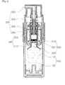
- Figure 6 is a disassembled cross sectional view illustrating a mixing container for different contents according to a second embodiment of the present invention.
- Figure 7 is a cross sectional view illustrating an initial state of a mixing container for different contents according to a second embodiment of the present invention.
- Figure 8 is a cross sectional view illustrating a state that two contents are mixed in a mixing container for different contents according to a second embodiment of the present invention.
- Figures 9 to 10 are cross sectional views illustrating a conventional mixing container for different contents.
- the present invention has two embodiments, of which the first embodiment is directed to a container type and the second embodiment is directed to a tube type.
- the present invention has features in that two kinds of contents are mixed and used. It is preferred that the content stored in the storing compartment 110 is liquid. It is preferred that the content stored in the receiver member 510 is one among liquid content different from the content stored in the storing compartment 110, powder and solid contents.
- Figure 1 is a disassembled perspective view illustrating a mixing container for different contents according to a first embodiment of the present invention.
- Figure 2 is a disassembled cross sectional view illustrating a mixing container for different contents according to a first embodiment of the present invention.
- Figure 3 is a cross sectional view illustrating an initial state of a mixing container for different contents according to a first embodiment of the present invention.
- Figure 4 is a cross sectional view illustrating a state that two contents are mixed in a mixing container for different contents according to a first embodiment of the present invention.
- Figure 5 is a cross sectional view illustrating a state that the piston of mixing container for different contents has moved to the top dead point according to a first embodiment of the present invention.
- the mixing container for different contents comprises a housing 100, a guide bracket 200, a button part 300, a sealing ring 400 and a storing container 500.
- a storing compartment 110 There may be further provided a storing compartment 110, a piston 120, an engaging shoulder 210, a guide piece 220, a discharge port 310, a pumping member 320, a guide groove 330, an insertion groove 340, a parting handle 410, a receiver member 510, a sealing member 520 and a communication hole 521.
- the housing 100 is a member with a storing compartment 110 storing contents, and a piston 120 is installed in the storing compartment 110.
- the piston 120 moves upward in contact with the inner wall of the storing compartment 110 during the pumping of the pumping member 320, thus keeping the interior of the pumping member 320 in a vacuum state.
- the housing 100 is made from a plastic or metallic content with a certain strength high enough to keep a vacuum state.
- the guide bracket 200 is a member engaged to the top of the housing 100. It is preferred that the guide bracket 200 is elastically engaged to the top of the housing 100. As shown in Figure 2 , an engaging shoulder 210 protrudes for its lower side to orient to the inner side.
- the engaging shoulder 210 protrudes toward the inner side of the storing compartment 110 when engaging to the housing 100.
- a guide piece 220 prolonging toward the upper side.
- the guide piece 220 serves to guide the up and down movements of the pumping member 320.
- the button part 300 is a member installed at the top of the guide bracket 200. At the button part 300 is provided a guide groove 330 engaging to the guide piece 220.
- the guide groove 330 engages with the guide piece 220 for the button part 300 to drive up and down.
- the button part 300 comprises a pumping member 320.
- the pumping member 320 is connected with the communication hole 521 of the sealing member 520 for thereby discharging the content in the interior of the housing 100 to the outside by way of the discharge port 310.
- the construction and operation principles of the pumping member 320 are known art, so the descriptions thereon will be omitted.
- an insertion groove 340 the bottom of which is open is provided at the inner side of the button part 300. As shown in Figure 2 , the insertion groove 340 covers the lower outer surface of the pumping member 320.
- the lower side of the receiver member 510 is sealingly engaged to the insertion groove 340 by means of a sealing member. At this time, it is preferred that the sealing member 520 is elastically engaged with the pumping member 320.
- the sealing member 400 is a member disposed between the guide bracket 200 and the button part 300.
- the sealing ring 400 serves to space apart the guide bracket 200 and the button part 300, and when in use, it parts for the guide bracket 200 to engage with the button part 300.
- the button part 300 moves downward by means of the guide piece 220 of the guide bracket 200, and at the same time the sealing member 520 moves downward, and the content stored in the interior of the receiver member 510 and the content stored in the interior of the storing compartment 110 come to mix with each other.
- the parting ring 400 consists of a parting handle 410 for easier parting work.
- the accommodation container 500 is formed of a receiver member 510 storing the content which is different from the content stored in the storing compartment 110, and a sealing member 520 which is elastically engaged to the lower side of the receiver member 510.
- the receiver member 510 is a member inserted in the insertion groove 340.
- the receiver member 510 is formed in a donut shape the lower side and center of which are open, with content being stored in the interior of the same.
- the receiver member 510 is supported by the engaging shoulder 210 for its lower side not to enter the interior of the housing 100.
- the sealing member 520 is a member selectively sealing the lower side of the receiver member 510.
- the sealing member 520 serves to separate the contents stored in the interior of the sealing member 520 and stored in the storing compartment 110 when the product of the first embodiment of the present invention is not used.
- the top of the sealing member 520 is engaged to the lower side of the pumping member 320.
- the sealing member 520 serves to open the lower side of the receiver member 510 as it moves downward by means of the button part 300 which moves when parting the sealing ring 400.
- a communication hole 521 communicating with the pumping member 320.
- the content can discharge from the interior of the storing compartment 110 through the discharge port 310 during the pumping of the pumping member 320.
- the second embodiment of the present invention has features in that the guide bracket 200 of the first embodiment is removed.
- the thread engagements of the housing 100 and the button part 300 are added instead of the use of the guide bracket 200.
- the button part 300 of the first embodiment moves up and down by the engagements of the guide piece 220 and the guide groove 330; however the button part 300 of the second embodiment moves up and down by the thread engagement with the protrusion part 130.
- Figure 6 is a disassembled cross sectional view illustrating a mixing container for different contents according to a second embodiment of the present invention.
- Figure 7 is a cross sectional view illustrating an initial state of a mixing container for different contents according to a second embodiment of the present invention.
- Figure 8 is a cross sectional view illustrating a state that two contents are mixed in a mixing container for different contents according to a second embodiment of the present invention.
- the mixing container for different contents comprises a housing 100, a button part 300, a sealing ring 400 and a storing container 500. There may be further provided a storing compartment 110, a protrusion part 130, a discharge port 310, a parting handle 410, a pumping member 320, a receiver member 510, a sealing member 520 and a fixing shoulder 530.
- the housing 100 is a member with a storing compartment 110 in its interior.
- the member serving as the piston 120 of the first embodiment is not provided in the interior of the housing 100.
- the housing 100 according to a second embodiment of the present invention is made from a flexible tube for the purpose of absorb as much contents as the discharged content amount depending on the pumping of the pumping member 320.
- protrusion part 130 From the top of the housing 100 protrudes a protrusion part 130. Content may input into the protrusion part 130, and threads are formed on its outer surface.
- the button part 300 is a member thread-engaged with the protrusion part 130.
- the button part 300 includes a discharge port 310 and a pumping member 320.
- the discharge port 310 and the pumping member 320 has the same functions as the discharge port 310 and the pumping member 320 of the first embodiment, so the description thereon will be omitted.
- the button part 300 ascends and descends in thread engagement with the protrusion part 130. When not in use, as shown in Figure 7 , it remains spaced apart from the housing 100 by the sealing ring 400 at a certain interval, and when in use, it rotates in one direction and moves downward, and the sealing member 520 moves downward by the button part 300, thus opening the lower side of the receiver member 510.
- the sealing ring 400 is a member installed between the housing 100 and the button part 300. As shown in Figure 7 , at the initial stage, in other words, the product of the present invention is packed, when not in use, the housing 100 and the button pat 300 are spaced apart from each other, and when in use the button part 300 moves downward.
- the button part 300 is thread-engaged with the threads of the protrusion part 130 and moves downward, and at the same time the sealing member 520 moves downward, so the content stored in the interior of the receiver member 510 and the content stored in the interior of the storing compartment 110 come to mix with each other.
- sealing ring 400 is equipped with a parting handle 410 for the sake of easier parting work.
- the storing container 500 comprises a fixing shoulder 530 protruding outward to be caught by an upper outer portion of the protrusion part 130 at the top of the same, an extension part 531 extending downward from the fixing shoulder 530, an accommodation part 510 storing the content different from the content stored in the storing compartment 110, and a sealing member 520 elastically connected to the lower side of the receiver member 510.
- the fixing shoulder 530 serves to fix the receiver member 510 and the sealing member 520 in places in the interior of the housing.
- the receiver member 510 is a member positioned in the interior of the housing 100 and is formed in a donut shape the lower and center sides of which are open, with the contents being stored in the interior of the same.
- the sealing member 520 is a member selectively sealing the lower side of the receiver member 510. When not in use, it helps separate the content stored in the interior of the sealing member 520 and the content stored in the storing compartment 110.
- the top of the sealing member 520 is engaged with the lower side of the pumping member 320.
- the sealing member 520 descends with the aid of the button part 300 which descends in the parting direction of the sealing ring 400, thus opening the lower side of the receiver member 510.
- a communication hole 521 communicating with the pumping member 320.
- the content stored in the interior of the storing compartment 110 can discharge through the discharge port 310 through the communication hole 521.
- Figure 3 shows the initial state of the mixing container for different contents according to a first embodiment of the present invention.
- the content stored in the storing compartment 110 and the content stored in the receiver member 510 keep separate by the sealing member 520.
- the user parts the sealing ring 400 with holding the parting handle 410, and the button part 300 is pressurized in the downward direction.
- the button part 300 descends along the guide piece 220, and it changes from the initial state of Figure 3 to the state of Figure 4 .
- the sealing member 520 descends by the pumping member 320, and the lower side of the receiver member 510 is opened.
- the content stored in the receiver member 510 comes into the storing compartment 110 and comes to mix with.
- the user lightly swings upward and downward holding the housing, so two contents mix well.
- the user light sways holding two contents, and the user pressurizes the button part 300 for the sake of pumping work.
- the interior of the housing 100 comes to vacuum, so the piston 120 ascends as long as the amount discharged through the discharge port 310.
- the piston 120 comes to positioned at the top dead point.
Landscapes
- Engineering & Computer Science (AREA)
- Mechanical Engineering (AREA)
- Package Specialized In Special Use (AREA)
- Containers And Packaging Bodies Having A Special Means To Remove Contents (AREA)
- Closures For Containers (AREA)
- Details Of Rigid Or Semi-Rigid Containers (AREA)
Applications Claiming Priority (2)
| Application Number | Priority Date | Filing Date | Title |
|---|---|---|---|
| KR1020100115971A KR101192603B1 (ko) | 2010-11-22 | 2010-11-22 | 이종 내용물 혼합용기 |
| PCT/KR2011/008920 WO2012070843A2 (ko) | 2010-11-22 | 2011-11-22 | 이종 내용물 혼합용기 |
Publications (2)
| Publication Number | Publication Date |
|---|---|
| EP2644532A2 true EP2644532A2 (de) | 2013-10-02 |
| EP2644532A4 EP2644532A4 (de) | 2017-08-09 |
Family
ID=46146285
Family Applications (1)
| Application Number | Title | Priority Date | Filing Date |
|---|---|---|---|
| EP11842947.1A Withdrawn EP2644532A4 (de) | 2010-11-22 | 2011-11-22 | Mischbehälter für verschiedene materialien |
Country Status (6)
| Country | Link |
|---|---|
| US (1) | US9434526B2 (de) |
| EP (1) | EP2644532A4 (de) |
| JP (1) | JP6217975B2 (de) |
| KR (1) | KR101192603B1 (de) |
| CN (1) | CN103201191B (de) |
| WO (1) | WO2012070843A2 (de) |
Families Citing this family (41)
| Publication number | Priority date | Publication date | Assignee | Title |
|---|---|---|---|---|
| DE102008030623A1 (de) * | 2008-01-03 | 2009-07-09 | Umsonst-Kübler, Petra | Vorrichtung zum Durchmischen einer Masse |
| KR101478978B1 (ko) | 2013-01-15 | 2015-01-07 | (주)연우 | 이종 내용물 혼합용기 |
| KR101481959B1 (ko) * | 2013-03-05 | 2015-02-04 | (주)연우 | 잔량 개선을 위한 이종 내용물 혼합용기 |
| USD723934S1 (en) * | 2013-05-24 | 2015-03-10 | Yonwoo Co., Ltd. | Cosmetic container |
| KR101431518B1 (ko) * | 2013-09-04 | 2014-08-21 | 주식회사 에프에스코리아 | 화장품 이액용기 |
| KR101389530B1 (ko) * | 2013-10-07 | 2014-05-27 | 주식회사 두코 | 이종물질혼합용기 |
| KR101479223B1 (ko) | 2014-01-21 | 2015-01-12 | 주식회사 네스필러피케이지 | 내용물 잔량 소진상태 확인이 용이한 에어리스 펌프 |
| USD737149S1 (en) * | 2014-04-01 | 2015-08-25 | Amorepacific Corporation | Cosmetic container |
| KR101544922B1 (ko) | 2014-06-23 | 2015-08-18 | (주)인젝타 | 골시멘트 혼합 및 주입용 카트리지 및 상기 카트리지를 포함하는 골시멘트 혼합 및 전달시스템 |
| CN104223733B (zh) * | 2014-07-21 | 2017-05-31 | 黑龙江省科学院火山与矿泉研究所 | 一种内部混合搅拌式化妆品存放装置 |
| CH710030A2 (de) * | 2014-08-27 | 2016-02-29 | Mühlemann Ip Gmbh | Dosiervorrichtung aus Kunststoff, die zur dichtenden Befestigung auf einem Flaschenhals ausgestaltet ist. |
| KR101503239B1 (ko) * | 2014-09-25 | 2015-03-18 | (주)연우 | 이종 내용물 저장 용기 |
| CA2964819A1 (en) * | 2014-10-20 | 2016-04-28 | Rieke Packaging Systems Limited | Pump dispensers |
| KR101635810B1 (ko) * | 2015-04-10 | 2016-07-04 | (주)연우 | 이종 내용물 혼합용기 |
| BR112019000996A2 (pt) * | 2016-07-18 | 2019-05-14 | Rpc Bramlage Gmbh | dispenser para massas líquidas até pastosas |
| KR101879205B1 (ko) | 2016-07-27 | 2018-07-17 | (주)연우 | 이종 내용물 혼합 용기 |
| KR101881043B1 (ko) * | 2016-11-28 | 2018-07-24 | 주식회사 케이알 | 이액형 화장품 용기 |
| AU2017382833C1 (en) * | 2016-12-20 | 2020-08-27 | Elc Management Llc | Fresh cosmetic composition delivery system |
| FR3065156B1 (fr) | 2017-04-14 | 2019-06-21 | L'oreal | Ensemble de conditionnement et de distribution d'un produit fluide bi-composant |
| USD834425S1 (en) * | 2017-05-15 | 2018-11-27 | Shiseido Co., Ltd. | Bottle for cosmetics |
| KR102020455B1 (ko) * | 2018-02-14 | 2019-09-11 | 펌텍코리아(주) | 누름버튼의 하강 거리가 조절되는 스포이드형 화장품 용기 |
| CN108703579B (zh) * | 2018-04-23 | 2021-05-07 | 铜陵昌盛家具有限责任公司 | 一种持续散香型木床 |
| JP7118540B2 (ja) * | 2018-08-30 | 2022-08-16 | 株式会社吉野工業所 | 混合吐出容器 |
| KR102252534B1 (ko) * | 2018-12-14 | 2021-05-14 | (주)아모레퍼시픽 | 화장료 혼합용 주 용기, 화장료 혼합용 보조 용기 및 이들을 포함하는 화장품 |
| KR102206002B1 (ko) * | 2019-06-19 | 2021-01-21 | 주식회사 케이알 | 이액형 화장품 용기 |
| CN110589213B (zh) * | 2019-09-26 | 2024-09-17 | 富祥塑胶制品(上海)有限公司 | 滴管装置 |
| WO2021125396A1 (ko) * | 2019-12-19 | 2021-06-24 | 주식회사 에프에스코리아 | 이종 화장품 믹싱 용기 |
| WO2021149331A1 (ja) * | 2020-01-22 | 2021-07-29 | 株式会社三谷バルブ | 分別廃棄可能な噴出容器、および、内容物噴出ユニット |
| USD991785S1 (en) | 2020-01-31 | 2023-07-11 | Armin Arminak | Lotion pump actuator |
| KR20210114086A (ko) | 2020-03-09 | 2021-09-23 | 주식회사 태성산업 | 내용물 전량 배출사용이 가능한 에어리스 타입 이종 내용물 혼합용기 |
| CN111547388B (zh) * | 2020-04-26 | 2022-07-12 | 浙江伟飒塑业有限公司 | 一种吸液结构及具有该结构的容器 |
| CN111547387B (zh) * | 2020-04-26 | 2022-07-12 | 浙江伟飒塑业有限公司 | 一种喷瓶 |
| CN111703695B (zh) * | 2020-07-15 | 2024-08-23 | 上海秀枝雪包装有限公司 | 一种真空软包泵压双舱式化妆品容器 |
| CN112273837B (zh) * | 2020-11-13 | 2024-12-31 | 郗大伟 | 一种缓存式滚珠包装瓶 |
| JP7438638B2 (ja) * | 2020-11-27 | 2024-02-27 | 株式会社吉野工業所 | 粉噴出容器 |
| US11498089B2 (en) | 2021-04-04 | 2022-11-15 | Armin Arminak | All plastic continuous spray trigger sprayer |
| EP4086008A1 (de) * | 2021-05-04 | 2022-11-09 | Aptar Radolfzell GmbH | Tropfenspender, flüssigkeitsspender und verfahren zur herstellung eines flüssigkeitsspenders |
| CN113335702A (zh) * | 2021-07-16 | 2021-09-03 | 浙江瑞昶实业有限公司 | 一种化妆品包装瓶 |
| US20230092170A1 (en) * | 2021-09-23 | 2023-03-23 | Apackaging Group Llc | All Plastic High Pressure Pump |
| CN117284613A (zh) * | 2022-06-14 | 2023-12-26 | 西尔格定量泵(无锡)有限公司 | 分配器 |
| DE102023102632B4 (de) * | 2023-02-02 | 2026-04-30 | Gaplast Gmbh | Kartuschensystem zur Abgabe einer wässrigen Lösung |
Family Cites Families (17)
| Publication number | Priority date | Publication date | Assignee | Title |
|---|---|---|---|---|
| US4727985A (en) * | 1986-02-24 | 1988-03-01 | The Boc Group, Inc. | Mixing and dispensing apparatus |
| DE4206524C2 (de) * | 1992-03-02 | 1997-04-24 | Andris Raimund Gmbh & Co Kg | Dosierpumpe für zähflüssige, insbesondere pastenartige Stoffe |
| FR2750397B1 (fr) * | 1996-06-28 | 1998-08-07 | Oreal | Dispositif pour le stockage separe d'au moins deux produits, leur melange et la distribution du melange ainsi obtenu et procede de fabrication |
| IT1292677B1 (it) * | 1997-02-28 | 1999-02-11 | Bormioli Metalplast Spa | Confezione per mantenere separati dei prodotti prima dell'uso. |
| DE19742559C2 (de) * | 1997-09-26 | 1999-08-05 | Gaplast Gmbh | Behälter mit Pumpe |
| ATE390960T1 (de) * | 1999-02-14 | 2008-04-15 | Pfeiffer Erich Gmbh & Co Kg | Spender für fliessfähige medien |
| KR200266847Y1 (ko) | 2001-12-05 | 2002-03-04 | (주)연우 | 디스펜서 |
| JP4400705B2 (ja) * | 2002-03-29 | 2010-01-20 | 株式会社タニ | 内容物の混合構造を有する包装容器 |
| KR200297647Y1 (ko) | 2002-03-29 | 2002-12-12 | 기근서 | 내용물 혼합구조를 갖는 포장용기 |
| KR200288637Y1 (ko) * | 2002-06-07 | 2002-09-11 | 임준국 | 혼합식 용기 |
| JP2004051104A (ja) * | 2002-07-16 | 2004-02-19 | Maruichi Valve Co Ltd | 二成分混合噴射装置 |
| KR20070076748A (ko) * | 2006-01-19 | 2007-07-25 | 삼성전자주식회사 | 휴대장치로 컨텐츠를 제공하는 컨텐츠제공장치 및 그의컨텐츠 제공방법 |
| KR200416576Y1 (ko) | 2006-03-06 | 2006-05-19 | (주)연우 | 디스펜서 용기 |
| ITMI20061266A1 (it) * | 2006-06-29 | 2007-12-30 | Microspray Delta Spa | Pompa semplificata di mandata di sostanze fluide prelevate da un contenitore |
| JP4781932B2 (ja) | 2006-07-31 | 2011-09-28 | 株式会社吉野工業所 | ポンプ付き二剤混合容器 |
| JP4818851B2 (ja) | 2006-08-31 | 2011-11-16 | 株式会社吉野工業所 | ポンプ付き二剤混合容器 |
| DE102007046625B4 (de) * | 2007-09-27 | 2012-06-06 | Gaplast Gmbh | Vorrichtung zum getrennten Aufbewahren einer Substanz, vorzugsweise eines medizinischen oder pharmazeutischen Wirkstoffs, und einer Flüssigkeit und zum Mischen derselben vor dem Gebrauch |
-
2010
- 2010-11-22 KR KR1020100115971A patent/KR101192603B1/ko not_active Expired - Fee Related
-
2011
- 2011-11-22 EP EP11842947.1A patent/EP2644532A4/de not_active Withdrawn
- 2011-11-22 JP JP2013539778A patent/JP6217975B2/ja not_active Expired - Fee Related
- 2011-11-22 US US13/879,774 patent/US9434526B2/en not_active Expired - Fee Related
- 2011-11-22 WO PCT/KR2011/008920 patent/WO2012070843A2/ko not_active Ceased
- 2011-11-22 CN CN201180053837.7A patent/CN103201191B/zh not_active Expired - Fee Related
Non-Patent Citations (1)
| Title |
|---|
| See references of WO2012070843A2 * |
Also Published As
| Publication number | Publication date |
|---|---|
| CN103201191B (zh) | 2015-02-18 |
| KR20120054716A (ko) | 2012-05-31 |
| JP6217975B2 (ja) | 2017-10-25 |
| KR101192603B1 (ko) | 2012-10-26 |
| JP2014500203A (ja) | 2014-01-09 |
| WO2012070843A3 (ko) | 2012-09-27 |
| WO2012070843A2 (ko) | 2012-05-31 |
| US9434526B2 (en) | 2016-09-06 |
| CN103201191A (zh) | 2013-07-10 |
| EP2644532A4 (de) | 2017-08-09 |
| US20130228482A1 (en) | 2013-09-05 |
Similar Documents
| Publication | Publication Date | Title |
|---|---|---|
| US9434526B2 (en) | Mixing container for different contents | |
| US12006128B2 (en) | Device for closing a container of a liquid to pasty product and refill closed by such a device | |
| US7866465B2 (en) | Multi-compartment storage and mixing vessel | |
| JP3405952B2 (ja) | 多成分系の保存混合機能兼有計量分配装置 | |
| US10034581B2 (en) | Dual content mixing container | |
| US10301087B2 (en) | Bottle for disposable one time use substance container | |
| US20190357656A1 (en) | Receptacle for mixing of different materials | |
| JP2014208542A (ja) | 二重容器 | |
| KR200480441Y1 (ko) | 자동 스포이드 용기 | |
| KR101817077B1 (ko) | 수동식 이중 분사장치 | |
| US10723537B2 (en) | Cartridge pump | |
| US20220169432A1 (en) | Mixing container having syringe | |
| JP4947792B2 (ja) | 複数液混合用エアゾール装置 | |
| AU2004287738B2 (en) | Method and structure for mixing different materials | |
| KR101071101B1 (ko) | 화장품 용기 | |
| CN217309436U (zh) | 不同种类化妆品混合容器 | |
| JP5046105B2 (ja) | 二剤混合容器 | |
| KR20130004528U (ko) | 수납공간이 분리된 혼합용기 | |
| US20070193893A1 (en) | Structure of cap having storage space | |
| KR20230028645A (ko) | 듀오믹스 기능을 가지는 화장품 용기용 캡 | |
| KR200493357Y1 (ko) | 이액 분리 저장이 가능한 앰플용기 | |
| EP2762420A2 (de) | Pumpenartiger röhrenbehälter | |
| KR101461853B1 (ko) | 음료용기 | |
| JP2003137374A (ja) | 液状流動体注出容器 | |
| JP2019026345A (ja) | 注出容器 |
Legal Events
| Date | Code | Title | Description |
|---|---|---|---|
| PUAI | Public reference made under article 153(3) epc to a published international application that has entered the european phase |
Free format text: ORIGINAL CODE: 0009012 |
|
| 17P | Request for examination filed |
Effective date: 20130612 |
|
| AK | Designated contracting states |
Kind code of ref document: A2 Designated state(s): AL AT BE BG CH CY CZ DE DK EE ES FI FR GB GR HR HU IE IS IT LI LT LU LV MC MK MT NL NO PL PT RO RS SE SI SK SM TR |
|
| DAX | Request for extension of the european patent (deleted) | ||
| A4 | Supplementary search report drawn up and despatched |
Effective date: 20170711 |
|
| RIC1 | Information provided on ipc code assigned before grant |
Ipc: A45D 34/04 20060101ALI20170704BHEP Ipc: B05B 11/00 20060101ALN20170704BHEP Ipc: B65D 81/32 20060101AFI20170704BHEP Ipc: B65D 25/08 20060101ALI20170704BHEP Ipc: B65D 83/76 20060101ALI20170704BHEP Ipc: A45D 34/00 20060101ALI20170704BHEP |
|
| GRAP | Despatch of communication of intention to grant a patent |
Free format text: ORIGINAL CODE: EPIDOSNIGR1 |
|
| RIC1 | Information provided on ipc code assigned before grant |
Ipc: B65D 81/32 20060101AFI20180706BHEP Ipc: B05B 11/00 20060101ALN20180706BHEP Ipc: A45D 34/04 20060101ALI20180706BHEP Ipc: B65D 25/08 20060101ALI20180706BHEP Ipc: A45D 34/00 20060101ALI20180706BHEP Ipc: B65D 83/76 20060101ALI20180706BHEP |
|
| RIC1 | Information provided on ipc code assigned before grant |
Ipc: A45D 34/04 20060101ALI20180716BHEP Ipc: A45D 34/00 20060101ALI20180716BHEP Ipc: B65D 25/08 20060101ALI20180716BHEP Ipc: B05B 11/00 20060101ALN20180716BHEP Ipc: B65D 83/76 20060101ALI20180716BHEP Ipc: B65D 81/32 20060101AFI20180716BHEP |
|
| INTG | Intention to grant announced |
Effective date: 20180731 |
|
| STAA | Information on the status of an ep patent application or granted ep patent |
Free format text: STATUS: THE APPLICATION IS DEEMED TO BE WITHDRAWN |
|
| 18D | Application deemed to be withdrawn |
Effective date: 20181211 |