EP2644560B1 - Table élévatrice à ciseaux - Google Patents
Table élévatrice à ciseaux Download PDFInfo
- Publication number
- EP2644560B1 EP2644560B1 EP13152404.3A EP13152404A EP2644560B1 EP 2644560 B1 EP2644560 B1 EP 2644560B1 EP 13152404 A EP13152404 A EP 13152404A EP 2644560 B1 EP2644560 B1 EP 2644560B1
- Authority
- EP
- European Patent Office
- Prior art keywords
- scissor
- lever
- unit
- base unit
- lift table
- Prior art date
- Legal status (The legal status is an assumption and is not a legal conclusion. Google has not performed a legal analysis and makes no representation as to the accuracy of the status listed.)
- Active
Links
Images

Classifications
-
- B—PERFORMING OPERATIONS; TRANSPORTING
- B66—HOISTING; LIFTING; HAULING
- B66F—HOISTING, LIFTING, HAULING OR PUSHING, NOT OTHERWISE PROVIDED FOR, e.g. DEVICES WHICH APPLY A LIFTING OR PUSHING FORCE DIRECTLY TO THE SURFACE OF A LOAD
- B66F7/00—Lifting frames, e.g. for lifting vehicles; Platform lifts
- B66F7/06—Lifting frames, e.g. for lifting vehicles; Platform lifts with platforms supported by levers for vertical movement
- B66F7/065—Scissor linkages, i.e. X-configuration
Definitions
- the invention relates to a scissor lift with the features of the preamble of claim 1.
- a scissor lift is for example from the document EP 1 454 873 B1 known and comprises a base unit, which may be provided for example with rollers or the like, and a support unit, which can be considered in the broadest sense as a height-adjustable table top and which is adjustable by means of a scissors unit, which is provided with a drive device, plane-parallel to the base unit.
- the scissor unit comprises based on a vertical table longitudinal center plane on both sides in each case a pair of scissor members with two scissor members, which are connected to each other via a hinge and one of which is mounted at one end to a fixedly arranged on the base unit, the first pivot bearing and with the other end movable on the Carrying unit is guided.
- the other scissor member is mounted at one end to a stationary arranged on the support unit, the second pivot bearing and guided at its other end movable on the base unit.
- the drive device has a complex lever construction on which a traction means in the form of a rope, a chain or a belt engages.
- the drive means comprises a toggle lever assembly.
- a first lever element of the toggle lever assembly engages one of the scissor members.
- a second lever element, which is connected to the first lever element, is provided with at least one windable tension element.
- the second lever element can be pivotally mounted on the base unit.
- the invention has for its object to provide a scissor lift of the aforementioned type with a respect to the introduction of force in the scissor unit optimized drive device.
- a scissor lifting table which comprises a base unit and a carrying unit which can be adjusted relative to the base unit by means of a scissor unit which is provided with a drive device.
- the scissors unit comprises at least one pair of scissor members with two scissor members, which are connected to one another via a hinge and one of which is mounted with one end to a fixedly arranged on the base unit, the first pivot bearing and is guided at the other end movable on the support unit.
- the other scissor member is mounted at one end to a stationary arranged on the support unit, the second pivot bearing and guided at its other end movable on the base unit.
- the drive device comprises a toggle lever arrangement, of which a first lever element acts on one of the scissor members and a second lever element connected to the first lever element, which is pivotably mounted on the base unit, is provided with at least one windable tension element.
- the second lever element mounted pivotably on the base unit has a curved guide surface against which the windable tension element rests.
- the tension element is a drive belt, which can be unwound for actuation of the support unit by a winding device or can be wound onto the winding device.
- the belts may be made of wear-resistant fabric so that the drive means of the scissor-lift shearing unit of the invention can withstand a variety of cycles of operation.
- the tension element is preferably guided via at least one deflection element, in particular via at least one deflection roller.
- the deflection roller may be arranged on the base unit or else be part of the toggle lever arrangement.
- the second lever element two has lateral shells with respect to a table longitudinal center plane, which are connected to one another via a guide device formed in particular by a guide plate, which forms the curved guide surface on which the at least one drive element engages.
- the scissor lift according to the invention has at least two tension elements which are arranged in parallel and engage the toggle lever arrangement and which can be wound on a common winding device.
- the winding device is actuated in particular by means of an electric motor and is connected to a transmission thereof.
- the tension element can be guided via a arranged on the second lever element deflecting surface to a suspension device which is fixed in the region of a hinge axis between the first lever member and the second lever element of the toggle lever assembly.
- a suspension device which is fixed in the region of a hinge axis between the first lever member and the second lever element of the toggle lever assembly.
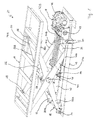
- a scissor lift 10 which serves for example for raising and lowering of high loads, for example in the field of a production line of an automobile manufacturer and arranged on a roller assembly, not shown, or can be mounted stationary.
- the scissor lift table 10 comprises a base unit 12 and a table-top-like support unit 14 arranged substantially plane-parallel to the base unit 12.
- the base unit 12 serves as a support for a scissor unit 16 and a drive unit 18 of the scissor unit 16.
- the scissors unit 16 comprises, relative to a vertical scissor table longitudinal center plane, a pair of scissor members 20A and 20B respectively formed from a first scissor member 22A and 22B and a second scissor member 24A and 24B crossing the respective first scissor member.
- the scissor members 22A and 24A and the scissor members 22B and 24B are connected to each other via transverse struts 26, 28 and 30 and 32, respectively.
- the first scissor members 22 A and 22 B are each pivotally mounted at one end to a pivot bearing 34 which is formed on the base unit 12. With the end facing away from the pivot bearing 34, the first scissor members 22A and 22B are each movably guided via a roller 36 in a guide rail 38A or 38B of the carrying unit 14.
- the second scissor members 24A and 24B are each pivotally mounted at one end to a pivot bearing 39, which on the support unit 14 above the pivot bearing 34 of the base unit 12 is arranged. With the end facing away from the pivot bearing 38, the second scissor members 24A and 24B are each guided via a roller 40 in a guide rail 42A or 42B formed on the base unit 12.
- the scissor members 22A and 24A and the scissor members 22B and 24B are pivotally connected to each other via a hinge 44, respectively.
- the scissor lifting table 10 comprises a drive unit 18 which comprises a drive motor 46 which rotatably actuates a winding shaft 48 serving as a winding device.
- a drive motor 46 which rotatably actuates a winding shaft 48 serving as a winding device.
- On the winding shaft 48 four parallel aligned drive belt or bands 50 are attached, which depending on the direction of rotation of the winding shaft 48 of this unwindable or can be wound on this.
- the drive belt 50 are guided from the winding shaft 48 via a roller-like deflection roller 52 to a toggle lever assembly 54.
- the toggle lever assembly 54 has, relative to the vertical scissor table longitudinal center plane on both sides in each case a first lever member 56 which is connected via an axis 58 with the associated scissor member 22A and 22B and at its end facing away from the axis 58 via a joint formed by a hinge axis 60 with a second lever member 61 is connected, which is pivotally mounted on the base unit 12 via a formed on a bearing block 62 joint 64.
- the second lever element 61 is formed from two lateral lever shells 66 which are each pivotally mounted via the joint 64 on the associated bearing block 62 and are connected to one another via a baffle 68 forming a guide surface.
- the drive belt 50 each representing a tension element, put on the guide plate 68 at.
- the drive belts 50 starting from the deflection roller 52 via the guide plate 68 and a round bar 70, which is formed on the second lever element 61 at the end remote from the hinge axis 60, are guided to a suspension device 72 which is suspended from the hinge axis 60.
- the drive motor 46 is actuated in such a way that the winding shaft 48 in accordance with Fig. 2 is rotated clockwise.
- the drive belt 50 are wound on the winding shaft 48, so that a tensile force is exerted on the second lever member 61 of the toggle lever assembly 54 and this exerts a deployment movement about the hinge 64.
- the winding shaft 48 is rotated counterclockwise, so that the drive belt 50 are unwound from the winding shaft 48.
- the second lever member 61 is pivoted, that is pivoted in the direction of the base unit 12, so that the support unit 14 is lowered due to gravity.
Landscapes
- Life Sciences & Earth Sciences (AREA)
- Engineering & Computer Science (AREA)
- Geology (AREA)
- Mechanical Engineering (AREA)
- Structural Engineering (AREA)
- Transmission Devices (AREA)
- Devices For Conveying Motion By Means Of Endless Flexible Members (AREA)
Claims (7)
- Table élévatrice à ciseaux ayant une unité de base (12) et une unité support (14) qui peut être ajustée par rapport à l'unité de base (12) au moyen d'une unité de ciseaux (16) étant pourvue d'un dispositif d'entraînement (18), l'unité de ciseaux (16) comprenant au moins une paire d'éléments de ciseaux (20A, 20B) ayant deux éléments de ciseaux (22A, 24A, 22B, 24B) qui sont reliés l'un à l'autre par une articulation et dont l'un a une extrémité montée sur un premier palier rotatif (34) étant disposé de manière fixe sur l'unité de base (12) et a l'autre extrémité guidée de manière déplaçable sur l'unité support (14) et l'autre a une extrémité montée sur un deuxième palier rotatif (39) étant disposé de manière fixe sur l'unité support (14) et a l'autre extrémité guidée de manière déplaçable sur l'unité de base (12), le dispositif d'entraînement (18) comprenant un agencement de leviers coudés (54) dont un premier élément de levier (56) engage un des éléments de ciseaux (22A, 22B) et un deuxième élément de levier (61) qui est relié au premier élément de levier (56) et monté de manière pivotante sur l'unité de base (12) est pourvu d'un élément de traction (50) enroulable,
caractérisée en ce que
le deuxième élément de levier (61) a une surface de guidage courbée sur laquelle s'appuie l'élément de traction (50) enroulable. - Table élévatrice à ciseaux selon la revendication 1,
caractérisée en ce que
l'élément de traction (50) est une courroie d'entraînement qui peut être déroulée d'un dispositif d'enroulement (48) ou peut être enroulée sur le dispositif d'enroulement (48) afin d'actionner l'unité support (14). - Table élévatrice à ciseaux selon la revendication 1 ou 2,
caractérisée en ce que
l'élément de traction (50) est guidé sur au moins un élément de déviation, in particulier sur au moins une poulie de déviation (52, 70). - Table élévatrice à ciseaux selon l'une quelconque des revendications 1 à 3,
caractérisée en ce que
l'élément de traction (50) est attaché à un dispositif de suspension (72) du deuxième élément de levier (61), le dispositif de suspension étant attaché dans la région d'un axe d'articulation (60) entre le premier élément de levier (56) et le deuxième élément de levier (61). - Table élévatrice à ciseaux selon la revendication 1,
caractérisée en ce que
le deuxième élément de levier (61) a deux coques de levier (66) latérales par rapport à un plan médian longitudinal de la table, les coques de levier étant reliées l'une à l'autre par un élément de guidage (68) qui forme la surface de guidage sur laquelle s'appuie l'au moins un élément d'entraînement (50). - Table élévatrice à ciseaux selon l'une quelconque des revendications 1 à 5,
caractérisée par
au moins deux éléments de traction (50) qui peuvent être enroulés sur un dispositif d'enroulement (48) commun. - Table élévatrice à ciseaux selon l'une quelconque des revendications 1 à 6,
caractérisée en ce qu'
une transmission intermédiaire à la manière d'un palan est interposée entre un moteur d'entraînement (46) et l'élément de traction.
Priority Applications (2)
| Application Number | Priority Date | Filing Date | Title |
|---|---|---|---|
| PL13152404T PL2644560T3 (pl) | 2012-03-27 | 2013-01-23 | Nożycowy stół podnośny |
| SI201330086T SI2644560T1 (sl) | 2012-03-27 | 2013-01-23 | Škarjasta dvižna miza |
Applications Claiming Priority (1)
| Application Number | Priority Date | Filing Date | Title |
|---|---|---|---|
| DE102012006028A DE102012006028A1 (de) | 2012-03-27 | 2012-03-27 | Scherenhubtisch |
Publications (2)
| Publication Number | Publication Date |
|---|---|
| EP2644560A1 EP2644560A1 (fr) | 2013-10-02 |
| EP2644560B1 true EP2644560B1 (fr) | 2015-08-05 |
Family
ID=47603426
Family Applications (1)
| Application Number | Title | Priority Date | Filing Date |
|---|---|---|---|
| EP13152404.3A Active EP2644560B1 (fr) | 2012-03-27 | 2013-01-23 | Table élévatrice à ciseaux |
Country Status (9)
| Country | Link |
|---|---|
| US (1) | US9340398B2 (fr) |
| EP (1) | EP2644560B1 (fr) |
| DE (1) | DE102012006028A1 (fr) |
| DK (1) | DK2644560T3 (fr) |
| ES (1) | ES2547702T3 (fr) |
| HU (1) | HUE028722T2 (fr) |
| PL (1) | PL2644560T3 (fr) |
| PT (1) | PT2644560E (fr) |
| SI (1) | SI2644560T1 (fr) |
Families Citing this family (18)
| Publication number | Priority date | Publication date | Assignee | Title |
|---|---|---|---|---|
| DE102008024051A1 (de) * | 2008-05-16 | 2009-11-19 | Maha Maschinenbau Haldenwang Gmbh & Co. Kg | Arretiervorrichtung |
| CN103954469B (zh) * | 2014-04-29 | 2016-03-16 | 湖南万通科技有限公司 | 一种采样机的升降机构 |
| US9387869B1 (en) | 2015-04-16 | 2016-07-12 | Aviad Berger | Luggage with mechanically integrated trolley |
| US10106378B2 (en) | 2015-11-03 | 2018-10-23 | General Electric Company | System and method for lifting with load moving machine |
| US11019920B2 (en) | 2016-09-23 | 2021-06-01 | Varidesk, Llc | Electrically-lifted computer desk and office desk thereof |
| CN206390562U (zh) | 2016-09-23 | 2017-08-11 | 廖良成 | 电动升降电脑桌及其办公桌 |
| US10745259B2 (en) * | 2016-10-27 | 2020-08-18 | BendPak, Inc. | Scissor-lift for vehicles |
| US11192763B2 (en) | 2016-10-27 | 2021-12-07 | BendPak, Inc. | Tilting scissor-lift for vehicles |
| USD825131S1 (en) * | 2016-12-16 | 2018-08-07 | Wik Gruppen As | Scissor lift |
| USD827241S1 (en) * | 2017-01-23 | 2018-08-28 | BendPak, Inc. | Vehicle parking lift |
| US10053343B1 (en) * | 2017-02-07 | 2018-08-21 | Rodney Cameron | Truck bed scissor lift |
| US10271642B1 (en) | 2018-02-27 | 2019-04-30 | Yi-Chen Tseng | Desk with combinative work surfaces |
| US10524568B2 (en) | 2018-02-27 | 2020-01-07 | Hi-Max Innovation Co., Ltd. | Adjustable desk with combinative work surface assemblies |
| CN108640029B (zh) * | 2018-05-25 | 2020-10-09 | 安徽三品技术服务有限公司 | 一种简便式汽车举升机 |
| USD891819S1 (en) * | 2019-09-16 | 2020-08-04 | Ningbo Kangying Metal Product Co., LTD | Lifting desk |
| GB2589642B (en) * | 2019-12-06 | 2024-02-14 | Mamas & Papas Holdings Ltd | Collapsible carry cot |
| GB2611329B (en) * | 2021-09-30 | 2024-02-21 | Accora Ltd | Bed lifting mechanism |
| USD1007804S1 (en) * | 2023-05-15 | 2023-12-12 | Bean's Best, LLC | Heavy-duty scissor jack |
Family Cites Families (16)
| Publication number | Priority date | Publication date | Assignee | Title |
|---|---|---|---|---|
| DE1445200U (fr) * | ||||
| US266226A (en) * | 1882-10-17 | underbill | ||
| US2706102A (en) * | 1951-06-06 | 1955-04-12 | Anthony L Cresci | Lifting mechanism for truck body |
| DE2635197A1 (de) * | 1976-08-05 | 1978-02-09 | Trepel Ag | Scherenhebetisch |
| US4926760A (en) * | 1989-01-27 | 1990-05-22 | Sack Allen J | Self leveling tables |
| JP2560869Y2 (ja) * | 1993-09-02 | 1998-01-26 | 杉安工業株式会社 | 作業台 |
| DE19716760A1 (de) * | 1997-04-12 | 1998-10-15 | Herold & Semmler Transporttech | Einrichtung zum Heben von Lasten |
| DE10228168A1 (de) * | 2002-06-24 | 2004-01-22 | Trepel GmbH, Hebe- und Fördertechnik | Scherenhebetisch |
| DE20302374U1 (de) * | 2003-02-14 | 2003-05-08 | Flexlift-Hubgeräte GmbH, 33609 Bielefeld | Scherenhubtisch |
| ATE346011T1 (de) * | 2003-03-04 | 2006-12-15 | Pro Hub Hebetechnik Gmbh | Scherenhubvorrichtung |
| DE20316905U1 (de) * | 2003-11-04 | 2005-03-17 | Expert Maschb Gmbh | Scheren-Hubtisch |
| ITFI20040149A1 (it) * | 2004-06-29 | 2004-09-29 | Stempa Di Mario Gonzi | Dispositivo di sollevamento di carichi |
| US20060037518A1 (en) * | 2004-08-17 | 2006-02-23 | Adelardo Lopez Alba | Power-operated scissor lift table |
| US7059616B2 (en) * | 2004-08-17 | 2006-06-13 | Super Made Products Co., Ltd. | Cutting machine push cart |
| DE102004061182A1 (de) * | 2004-12-16 | 2006-06-22 | Laweco Maschinen- Und Apparatebau Gmbh | Scherenhubtisch |
| DE102006006467B4 (de) * | 2006-02-10 | 2008-09-11 | Grundei Hebetische Verladetechnik Gmbh | Scherenhubtisch |
-
2012
- 2012-03-27 DE DE102012006028A patent/DE102012006028A1/de not_active Withdrawn
-
2013
- 2013-01-23 PT PT131524043T patent/PT2644560E/pt unknown
- 2013-01-23 PL PL13152404T patent/PL2644560T3/pl unknown
- 2013-01-23 HU HUE13152404A patent/HUE028722T2/en unknown
- 2013-01-23 ES ES13152404.3T patent/ES2547702T3/es active Active
- 2013-01-23 EP EP13152404.3A patent/EP2644560B1/fr active Active
- 2013-01-23 SI SI201330086T patent/SI2644560T1/sl unknown
- 2013-01-23 DK DK13152404.3T patent/DK2644560T3/en active
- 2013-03-19 US US13/847,399 patent/US9340398B2/en active Active
Also Published As
| Publication number | Publication date |
|---|---|
| US20130256611A1 (en) | 2013-10-03 |
| ES2547702T3 (es) | 2015-10-08 |
| PL2644560T3 (pl) | 2016-03-31 |
| DK2644560T3 (en) | 2015-11-16 |
| EP2644560A1 (fr) | 2013-10-02 |
| HUE028722T2 (en) | 2016-12-28 |
| US9340398B2 (en) | 2016-05-17 |
| DE102012006028A1 (de) | 2013-10-02 |
| SI2644560T1 (sl) | 2015-12-31 |
| PT2644560E (pt) | 2015-10-16 |
Similar Documents
| Publication | Publication Date | Title |
|---|---|---|
| EP2644560B1 (fr) | Table élévatrice à ciseaux | |
| EP0983897B1 (fr) | Dispositif de levage | |
| EP2694428B1 (fr) | Table élévatrice à ciseaux | |
| EP2426258B1 (fr) | Convoyeur et engin doté d'un convoyeur | |
| DE69000289T2 (de) | Kran mit anhebbarem ausleger und mit einer ausleger-rueckstossvorrichtung. | |
| EP1700811B1 (fr) | Ascenseur | |
| DE2902116A1 (de) | Vorrichtung zum austausch des regelstab-antriebs in einem kernreaktor | |
| EP2512968B1 (fr) | Installation d'ascenseur à double cabine | |
| EP3119713A1 (fr) | Ascenseur équipé d'un dispositif de tension de câble de compensation | |
| DE202012003063U1 (de) | Scherenhubtisch | |
| EP3732124A1 (fr) | Dispositif pour le stationnement de véhicules | |
| DE10228168A1 (de) | Scherenhebetisch | |
| EP2010736A1 (fr) | Système de garage pour véhicules à moteur | |
| DE202005019439U1 (de) | Hebebühne | |
| DE102004061182A1 (de) | Scherenhubtisch | |
| AT10692U1 (de) | Hebe- und schwenkeinrichtung | |
| EP2935086A1 (fr) | Table élévatrice à ciseaux | |
| EP4091970B1 (fr) | Dispositif de levage de charges | |
| DE102010013390B3 (de) | Vorrichtung zum Anbringen und Absetzen eines Gegengewichts einer Baumaschine, Set umfassend eine derartige Vorrichtung und Baumaschine, insbesondere Kettenbagger, mit einer derartigen Vorrichtung oder einem derartigen Set | |
| DE102016110033A1 (de) | Hubvorrichtung | |
| DE102005024289A1 (de) | Scherenhubtisch | |
| EP3020674A1 (fr) | Ascenseur de service | |
| DE102017205035A1 (de) | Anordnung zur Führung eines Lastschlittens | |
| DE202023107248U1 (de) | Untergestell für einen Arbeits- oder Montagetisch | |
| EP2641575B1 (fr) | Plate-forme élévatrice de véhicule avec dispositif de précontrainte |
Legal Events
| Date | Code | Title | Description |
|---|---|---|---|
| PUAI | Public reference made under article 153(3) epc to a published international application that has entered the european phase |
Free format text: ORIGINAL CODE: 0009012 |
|
| AK | Designated contracting states |
Kind code of ref document: A1 Designated state(s): AL AT BE BG CH CY CZ DE DK EE ES FI FR GB GR HR HU IE IS IT LI LT LU LV MC MK MT NL NO PL PT RO RS SE SI SK SM TR |
|
| AX | Request for extension of the european patent |
Extension state: BA ME |
|
| 17P | Request for examination filed |
Effective date: 20140207 |
|
| RBV | Designated contracting states (corrected) |
Designated state(s): AL AT BE BG CH CY CZ DE DK EE ES FI FR GB GR HR HU IE IS IT LI LT LU LV MC MK MT NL NO PL PT RO RS SE SI SK SM TR |
|
| GRAP | Despatch of communication of intention to grant a patent |
Free format text: ORIGINAL CODE: EPIDOSNIGR1 |
|
| INTG | Intention to grant announced |
Effective date: 20150212 |
|
| GRAS | Grant fee paid |
Free format text: ORIGINAL CODE: EPIDOSNIGR3 |
|
| GRAP | Despatch of communication of intention to grant a patent |
Free format text: ORIGINAL CODE: EPIDOSNIGR1 |
|
| GRAA | (expected) grant |
Free format text: ORIGINAL CODE: 0009210 |
|
| INTG | Intention to grant announced |
Effective date: 20150624 |
|
| AK | Designated contracting states |
Kind code of ref document: B1 Designated state(s): AL AT BE BG CH CY CZ DE DK EE ES FI FR GB GR HR HU IE IS IT LI LT LU LV MC MK MT NL NO PL PT RO RS SE SI SK SM TR |
|
| REG | Reference to a national code |
Ref country code: GB Ref legal event code: FG4D Free format text: NOT ENGLISH |
|
| REG | Reference to a national code |
Ref country code: CH Ref legal event code: EP |
|
| REG | Reference to a national code |
Ref country code: AT Ref legal event code: REF Ref document number: 740574 Country of ref document: AT Kind code of ref document: T Effective date: 20150815 |
|
| REG | Reference to a national code |
Ref country code: IE Ref legal event code: FG4D Free format text: LANGUAGE OF EP DOCUMENT: GERMAN |
|
| REG | Reference to a national code |
Ref country code: DE Ref legal event code: R096 Ref document number: 502013000957 Country of ref document: DE |
|
| REG | Reference to a national code |
Ref country code: ES Ref legal event code: FG2A Ref document number: 2547702 Country of ref document: ES Kind code of ref document: T3 Effective date: 20151008 |
|
| REG | Reference to a national code |
Ref country code: PT Ref legal event code: SC4A Free format text: AVAILABILITY OF NATIONAL TRANSLATION Effective date: 20150917 |
|
| REG | Reference to a national code |
Ref country code: NO Ref legal event code: T2 Effective date: 20150805 |
|
| REG | Reference to a national code |
Ref country code: DK Ref legal event code: T3 Effective date: 20151113 |
|
| REG | Reference to a national code |
Ref country code: SE Ref legal event code: TRGR |
|
| REG | Reference to a national code |
Ref country code: NL Ref legal event code: FP |
|
| REG | Reference to a national code |
Ref country code: LT Ref legal event code: MG4D |
|
| REG | Reference to a national code |
Ref country code: FR Ref legal event code: PLFP Year of fee payment: 4 |
|
| PG25 | Lapsed in a contracting state [announced via postgrant information from national office to epo] |
Ref country code: FI Free format text: LAPSE BECAUSE OF FAILURE TO SUBMIT A TRANSLATION OF THE DESCRIPTION OR TO PAY THE FEE WITHIN THE PRESCRIBED TIME-LIMIT Effective date: 20150805 Ref country code: GR Free format text: LAPSE BECAUSE OF FAILURE TO SUBMIT A TRANSLATION OF THE DESCRIPTION OR TO PAY THE FEE WITHIN THE PRESCRIBED TIME-LIMIT Effective date: 20151106 Ref country code: LT Free format text: LAPSE BECAUSE OF FAILURE TO SUBMIT A TRANSLATION OF THE DESCRIPTION OR TO PAY THE FEE WITHIN THE PRESCRIBED TIME-LIMIT Effective date: 20150805 Ref country code: LV Free format text: LAPSE BECAUSE OF FAILURE TO SUBMIT A TRANSLATION OF THE DESCRIPTION OR TO PAY THE FEE WITHIN THE PRESCRIBED TIME-LIMIT Effective date: 20150805 |
|
| PG25 | Lapsed in a contracting state [announced via postgrant information from national office to epo] |
Ref country code: IS Free format text: LAPSE BECAUSE OF FAILURE TO SUBMIT A TRANSLATION OF THE DESCRIPTION OR TO PAY THE FEE WITHIN THE PRESCRIBED TIME-LIMIT Effective date: 20151205 Ref country code: RS Free format text: LAPSE BECAUSE OF FAILURE TO SUBMIT A TRANSLATION OF THE DESCRIPTION OR TO PAY THE FEE WITHIN THE PRESCRIBED TIME-LIMIT Effective date: 20150805 Ref country code: HR Free format text: LAPSE BECAUSE OF FAILURE TO SUBMIT A TRANSLATION OF THE DESCRIPTION OR TO PAY THE FEE WITHIN THE PRESCRIBED TIME-LIMIT Effective date: 20150805 |
|
| PG25 | Lapsed in a contracting state [announced via postgrant information from national office to epo] |
Ref country code: SK Free format text: LAPSE BECAUSE OF FAILURE TO SUBMIT A TRANSLATION OF THE DESCRIPTION OR TO PAY THE FEE WITHIN THE PRESCRIBED TIME-LIMIT Effective date: 20150805 Ref country code: EE Free format text: LAPSE BECAUSE OF FAILURE TO SUBMIT A TRANSLATION OF THE DESCRIPTION OR TO PAY THE FEE WITHIN THE PRESCRIBED TIME-LIMIT Effective date: 20150805 Ref country code: CZ Free format text: LAPSE BECAUSE OF FAILURE TO SUBMIT A TRANSLATION OF THE DESCRIPTION OR TO PAY THE FEE WITHIN THE PRESCRIBED TIME-LIMIT Effective date: 20150805 |
|
| REG | Reference to a national code |
Ref country code: DE Ref legal event code: R097 Ref document number: 502013000957 Country of ref document: DE |
|
| PG25 | Lapsed in a contracting state [announced via postgrant information from national office to epo] |
Ref country code: RO Free format text: LAPSE BECAUSE OF FAILURE TO SUBMIT A TRANSLATION OF THE DESCRIPTION OR TO PAY THE FEE WITHIN THE PRESCRIBED TIME-LIMIT Effective date: 20150805 |
|
| PLBE | No opposition filed within time limit |
Free format text: ORIGINAL CODE: 0009261 |
|
| STAA | Information on the status of an ep patent application or granted ep patent |
Free format text: STATUS: NO OPPOSITION FILED WITHIN TIME LIMIT |
|
| 26N | No opposition filed |
Effective date: 20160509 |
|
| PG25 | Lapsed in a contracting state [announced via postgrant information from national office to epo] |
Ref country code: LU Free format text: LAPSE BECAUSE OF FAILURE TO SUBMIT A TRANSLATION OF THE DESCRIPTION OR TO PAY THE FEE WITHIN THE PRESCRIBED TIME-LIMIT Effective date: 20160123 |
|
| REG | Reference to a national code |
Ref country code: CH Ref legal event code: PL |
|
| PG25 | Lapsed in a contracting state [announced via postgrant information from national office to epo] |
Ref country code: MC Free format text: LAPSE BECAUSE OF FAILURE TO SUBMIT A TRANSLATION OF THE DESCRIPTION OR TO PAY THE FEE WITHIN THE PRESCRIBED TIME-LIMIT Effective date: 20150805 |
|
| PG25 | Lapsed in a contracting state [announced via postgrant information from national office to epo] |
Ref country code: CH Free format text: LAPSE BECAUSE OF NON-PAYMENT OF DUE FEES Effective date: 20160131 Ref country code: LI Free format text: LAPSE BECAUSE OF NON-PAYMENT OF DUE FEES Effective date: 20160131 |
|
| REG | Reference to a national code |
Ref country code: IE Ref legal event code: MM4A |
|
| REG | Reference to a national code |
Ref country code: HU Ref legal event code: AG4A Ref document number: E028722 Country of ref document: HU |
|
| REG | Reference to a national code |
Ref country code: FR Ref legal event code: PLFP Year of fee payment: 5 |
|
| PG25 | Lapsed in a contracting state [announced via postgrant information from national office to epo] |
Ref country code: IE Free format text: LAPSE BECAUSE OF NON-PAYMENT OF DUE FEES Effective date: 20160123 |
|
| PG25 | Lapsed in a contracting state [announced via postgrant information from national office to epo] |
Ref country code: MT Free format text: LAPSE BECAUSE OF FAILURE TO SUBMIT A TRANSLATION OF THE DESCRIPTION OR TO PAY THE FEE WITHIN THE PRESCRIBED TIME-LIMIT Effective date: 20150805 |
|
| REG | Reference to a national code |
Ref country code: FR Ref legal event code: PLFP Year of fee payment: 6 |
|
| PG25 | Lapsed in a contracting state [announced via postgrant information from national office to epo] |
Ref country code: SM Free format text: LAPSE BECAUSE OF FAILURE TO SUBMIT A TRANSLATION OF THE DESCRIPTION OR TO PAY THE FEE WITHIN THE PRESCRIBED TIME-LIMIT Effective date: 20150805 Ref country code: CY Free format text: LAPSE BECAUSE OF FAILURE TO SUBMIT A TRANSLATION OF THE DESCRIPTION OR TO PAY THE FEE WITHIN THE PRESCRIBED TIME-LIMIT Effective date: 20150805 |
|
| PG25 | Lapsed in a contracting state [announced via postgrant information from national office to epo] |
Ref country code: MK Free format text: LAPSE BECAUSE OF FAILURE TO SUBMIT A TRANSLATION OF THE DESCRIPTION OR TO PAY THE FEE WITHIN THE PRESCRIBED TIME-LIMIT Effective date: 20150805 Ref country code: TR Free format text: LAPSE BECAUSE OF FAILURE TO SUBMIT A TRANSLATION OF THE DESCRIPTION OR TO PAY THE FEE WITHIN THE PRESCRIBED TIME-LIMIT Effective date: 20150805 |
|
| PG25 | Lapsed in a contracting state [announced via postgrant information from national office to epo] |
Ref country code: BG Free format text: LAPSE BECAUSE OF FAILURE TO SUBMIT A TRANSLATION OF THE DESCRIPTION OR TO PAY THE FEE WITHIN THE PRESCRIBED TIME-LIMIT Effective date: 20150805 |
|
| PG25 | Lapsed in a contracting state [announced via postgrant information from national office to epo] |
Ref country code: AL Free format text: LAPSE BECAUSE OF FAILURE TO SUBMIT A TRANSLATION OF THE DESCRIPTION OR TO PAY THE FEE WITHIN THE PRESCRIBED TIME-LIMIT Effective date: 20150805 |
|
| PGFP | Annual fee paid to national office [announced via postgrant information from national office to epo] |
Ref country code: DK Payment date: 20200123 Year of fee payment: 8 Ref country code: IT Payment date: 20200122 Year of fee payment: 8 Ref country code: NL Payment date: 20200122 Year of fee payment: 8 Ref country code: NO Payment date: 20200123 Year of fee payment: 8 |
|
| PGFP | Annual fee paid to national office [announced via postgrant information from national office to epo] |
Ref country code: SI Payment date: 20200115 Year of fee payment: 8 |
|
| PGFP | Annual fee paid to national office [announced via postgrant information from national office to epo] |
Ref country code: FR Payment date: 20200123 Year of fee payment: 8 |
|
| REG | Reference to a national code |
Ref country code: DK Ref legal event code: EBP Effective date: 20210131 |
|
| REG | Reference to a national code |
Ref country code: NO Ref legal event code: MMEP |
|
| REG | Reference to a national code |
Ref country code: NL Ref legal event code: MM Effective date: 20210201 |
|
| PG25 | Lapsed in a contracting state [announced via postgrant information from national office to epo] |
Ref country code: NL Free format text: LAPSE BECAUSE OF NON-PAYMENT OF DUE FEES Effective date: 20210201 Ref country code: FR Free format text: LAPSE BECAUSE OF NON-PAYMENT OF DUE FEES Effective date: 20210131 |
|
| PG25 | Lapsed in a contracting state [announced via postgrant information from national office to epo] |
Ref country code: NO Free format text: LAPSE BECAUSE OF NON-PAYMENT OF DUE FEES Effective date: 20210131 |
|
| REG | Reference to a national code |
Ref country code: SI Ref legal event code: KO00 Effective date: 20211125 |
|
| PG25 | Lapsed in a contracting state [announced via postgrant information from national office to epo] |
Ref country code: DK Free format text: LAPSE BECAUSE OF NON-PAYMENT OF DUE FEES Effective date: 20210131 |
|
| PG25 | Lapsed in a contracting state [announced via postgrant information from national office to epo] |
Ref country code: SI Free format text: LAPSE BECAUSE OF NON-PAYMENT OF DUE FEES Effective date: 20210124 |
|
| PG25 | Lapsed in a contracting state [announced via postgrant information from national office to epo] |
Ref country code: IT Free format text: LAPSE BECAUSE OF NON-PAYMENT OF DUE FEES Effective date: 20210123 |
|
| P01 | Opt-out of the competence of the unified patent court (upc) registered |
Effective date: 20230530 |
|
| PGFP | Annual fee paid to national office [announced via postgrant information from national office to epo] |
Ref country code: PL Payment date: 20241216 Year of fee payment: 13 |
|
| PGFP | Annual fee paid to national office [announced via postgrant information from national office to epo] |
Ref country code: SE Payment date: 20260121 Year of fee payment: 14 |
|
| PGFP | Annual fee paid to national office [announced via postgrant information from national office to epo] |
Ref country code: GB Payment date: 20260122 Year of fee payment: 14 |
|
| PGFP | Annual fee paid to national office [announced via postgrant information from national office to epo] |
Ref country code: ES Payment date: 20260217 Year of fee payment: 14 |
|
| PGFP | Annual fee paid to national office [announced via postgrant information from national office to epo] |
Ref country code: DE Payment date: 20260316 Year of fee payment: 14 |
|
| PGFP | Annual fee paid to national office [announced via postgrant information from national office to epo] |
Ref country code: AT Payment date: 20260119 Year of fee payment: 14 |
|
| PGFP | Annual fee paid to national office [announced via postgrant information from national office to epo] |
Ref country code: BE Payment date: 20260121 Year of fee payment: 14 |
|
| PGFP | Annual fee paid to national office [announced via postgrant information from national office to epo] |
Ref country code: HU Payment date: 20260116 Year of fee payment: 14 |
|
| PGFP | Annual fee paid to national office [announced via postgrant information from national office to epo] |
Ref country code: PT Payment date: 20260120 Year of fee payment: 14 |