EP2644576A1 - Formkonstruktion zum Biegen von Glasscheiben - Google Patents
Formkonstruktion zum Biegen von Glasscheiben Download PDFInfo
- Publication number
- EP2644576A1 EP2644576A1 EP12161835.9A EP12161835A EP2644576A1 EP 2644576 A1 EP2644576 A1 EP 2644576A1 EP 12161835 A EP12161835 A EP 12161835A EP 2644576 A1 EP2644576 A1 EP 2644576A1
- Authority
- EP
- European Patent Office
- Prior art keywords
- mould
- support plates
- pipes
- slots
- construction
- Prior art date
- Legal status (The legal status is an assumption and is not a legal conclusion. Google has not performed a legal analysis and makes no representation as to the accuracy of the status listed.)
- Withdrawn
Links
- 238000010276 construction Methods 0.000 title claims abstract description 22
- 239000011521 glass Substances 0.000 title claims abstract description 16
- 238000005452 bending Methods 0.000 title claims abstract description 14
- 230000000694 effects Effects 0.000 claims abstract description 3
- 230000000284 resting effect Effects 0.000 claims abstract description 3
- 239000000835 fiber Substances 0.000 claims description 3
- 239000002184 metal Substances 0.000 claims description 3
- 229910000831 Steel Inorganic materials 0.000 claims description 2
- 229910000746 Structural steel Inorganic materials 0.000 claims description 2
- 239000004744 fabric Substances 0.000 claims description 2
- 239000004745 nonwoven fabric Substances 0.000 claims description 2
- 239000010959 steel Substances 0.000 claims description 2
- 238000004519 manufacturing process Methods 0.000 description 2
- 238000005496 tempering Methods 0.000 description 2
- 230000001419 dependent effect Effects 0.000 description 1
- 230000005855 radiation Effects 0.000 description 1
- 238000004904 shortening Methods 0.000 description 1
- 230000003068 static effect Effects 0.000 description 1
Images
Classifications
-
- C—CHEMISTRY; METALLURGY
- C03—GLASS; MINERAL OR SLAG WOOL
- C03B—MANUFACTURE, SHAPING, OR SUPPLEMENTARY PROCESSES
- C03B23/00—Re-forming shaped glass
- C03B23/02—Re-forming glass sheets
- C03B23/023—Re-forming glass sheets by bending
- C03B23/025—Re-forming glass sheets by bending by gravity
- C03B23/0252—Re-forming glass sheets by bending by gravity by gravity only, e.g. sagging
- C03B23/0254—Re-forming glass sheets by bending by gravity by gravity only, e.g. sagging in a continuous way, e.g. gravity roll bending
-
- C—CHEMISTRY; METALLURGY
- C03—GLASS; MINERAL OR SLAG WOOL
- C03B—MANUFACTURE, SHAPING, OR SUPPLEMENTARY PROCESSES
- C03B2225/00—Transporting hot glass sheets during their manufacture
- C03B2225/02—Means for positioning, aligning or orientating the sheets during their travel, e.g. stops
-
- C—CHEMISTRY; METALLURGY
- C03—GLASS; MINERAL OR SLAG WOOL
- C03B—MANUFACTURE, SHAPING, OR SUPPLEMENTARY PROCESSES
- C03B40/00—Preventing adhesion between glass and glass or between glass and the means used to shape it, hold it or support it
- C03B40/005—Fabrics, felts or loose covers
Definitions
- the object of the invention is a mould construction for bending glass sheets, the said mould construction comprising
- the aim of the invention is to develop the mould construction mentioned above further so as to achieve accurate control of form by means of it.
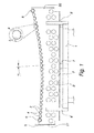
- the described mould construction comprises a framework 1 made of structural steel on which are supported support plates 2 on vertical planes. There are several, for example 5, support plates 2 at a horizontal distance from one another. The support plates are parallel with one another. The curvature of the upper edge of the support plates 2 corresponds essentially to the desired bending curvature of the glass sheet.
- the upper edges of the support plates 2 comprise slots 3, in which are placed pipes 4, which form the mould surface. If necessary, there may be a non-woven mat or non-woven fabric on the pipes 4 for forming a uniform mould surface.
- the support plates 2 and pipes 4 are made of stainless or acid-proof steel.
- the slots 3 are dimensioned to receive the pipes 4 with play but, however, in such a way that the upward movement of the pipes 4 from the slots 3 is prevented.
- the lengthening and shortening of the pipes due to the varying temperature will thus not affect the shape of the support surface.
- the pipes 4 are pushed in their longitudinal direction through the slots 3 of all support plates 2.
- the pipes are free to expand by heat and will not warp.
- the pipes 4 and the slots 3 are shown on a relatively larger scale than in the real construction, where also the number of pipes 4 is about double that shown in the Figure.
- the diameter of the pipes 4 is between 15-25 mm and the gap between the pipes is between 4-8 mm.
- the wall thickness of the pipes 4 is 0.5-0.8 mm, that is, the pipes are relatively ductile and flexible. For this reason, there are at least four or five support plates 2 divided over the length of the pipes.
- the support plates 2 are supported on the framework in such a way that one end of the mould surface is lower than the other end. In the embodiment shown this is implemented in such a way that the support plates 2 are higher at one end 22 than the other end 21. In that case, the central axis of the parabola drawn through the centres of the slots 3 in the row of slots is correspondingly tilted, that is, deviates from the vertical plane towards the lower end 21 by angle a.
- the support plates 2 at the lower end of the mould surface are provided with end stoppers 5 and the said difference in height, that is, the inclination of the mould surface is dimensioned so as to effect the resting of the edge of the glass sheet placed on the mould against the end stoppers 5 during the bending stage.
- the advantage of this construction is that the static friction between the glass sheet placed on the mould and the mould surface is converted into sliding friction evenly throughout and the glass sheet rests against the stoppers 5 all the time at the same point of the mould.
- a rotating, tubular non-woven metal fibre fabric 6 which facilitates the sliding of the other end of the glass sheet during bending.
- At the other end is preferably also a metal fibre pipe 6 around the pipe 4.
- the support plates 2 are fixed by their central area to the framework 1 by fasteners 7 which allow vertical movement but prevent horizontal movement.
- the framework 1 comprises slot-like supports 8 for supporting the ends of the support plates 2 against lateral inclination, but slidingly in its longitudinal direction. This arrangement together with the loose fitting of the pipes 4 ensures that the support plates 2 will not warp as a result of thermal expansion.
- the support plates 2 are, in addition, perforated in such a way that the proportion of the holes 9 is at least 25%, preferably more than 30%, of the surface area of the support plates 2. This lightens the structure and makes possible the circulation of air below the mould surface.
Landscapes
- Chemical & Material Sciences (AREA)
- Engineering & Computer Science (AREA)
- Materials Engineering (AREA)
- Organic Chemistry (AREA)
- Conveying And Assembling Of Building Elements In Situ (AREA)
Priority Applications (1)
| Application Number | Priority Date | Filing Date | Title |
|---|---|---|---|
| EP12161835.9A EP2644576A1 (de) | 2012-03-28 | 2012-03-28 | Formkonstruktion zum Biegen von Glasscheiben |
Applications Claiming Priority (1)
| Application Number | Priority Date | Filing Date | Title |
|---|---|---|---|
| EP12161835.9A EP2644576A1 (de) | 2012-03-28 | 2012-03-28 | Formkonstruktion zum Biegen von Glasscheiben |
Publications (1)
| Publication Number | Publication Date |
|---|---|
| EP2644576A1 true EP2644576A1 (de) | 2013-10-02 |
Family
ID=45888093
Family Applications (1)
| Application Number | Title | Priority Date | Filing Date |
|---|---|---|---|
| EP12161835.9A Withdrawn EP2644576A1 (de) | 2012-03-28 | 2012-03-28 | Formkonstruktion zum Biegen von Glasscheiben |
Country Status (1)
| Country | Link |
|---|---|
| EP (1) | EP2644576A1 (de) |
Citations (4)
| Publication number | Priority date | Publication date | Assignee | Title |
|---|---|---|---|---|
| DE237064C (de) * | ||||
| WO1990003334A1 (en) * | 1988-09-28 | 1990-04-05 | Glamec Oy | Glass bending mold |
| WO1990003336A1 (en) | 1988-09-28 | 1990-04-05 | Glamec Oy | Heating, bending and cooling system for glass |
| EP0571287A1 (de) * | 1992-05-21 | 1993-11-24 | Saint-Gobain Vitrage International | Verfahren und Vorrichtung zum Herstellen von gebogenen Glasscheiben |
-
2012
- 2012-03-28 EP EP12161835.9A patent/EP2644576A1/de not_active Withdrawn
Patent Citations (4)
| Publication number | Priority date | Publication date | Assignee | Title |
|---|---|---|---|---|
| DE237064C (de) * | ||||
| WO1990003334A1 (en) * | 1988-09-28 | 1990-04-05 | Glamec Oy | Glass bending mold |
| WO1990003336A1 (en) | 1988-09-28 | 1990-04-05 | Glamec Oy | Heating, bending and cooling system for glass |
| EP0571287A1 (de) * | 1992-05-21 | 1993-11-24 | Saint-Gobain Vitrage International | Verfahren und Vorrichtung zum Herstellen von gebogenen Glasscheiben |
Similar Documents
| Publication | Publication Date | Title |
|---|---|---|
| US20130255322A1 (en) | Mould construction for bending glass sheets | |
| EP2167435B1 (de) | Verfahren und vorrichtung zur herstellung einer doppelt gekrümmten scheibe aus einer flachen scheibe | |
| JP5957613B2 (ja) | 熱間プレス用鋼板の遠赤外線式多段型加熱炉 | |
| EP2088371A3 (de) | Wärmetauscherrahmenanordnung | |
| KR200488267Y1 (ko) | 다중 만곡 굴곡 유리 패널을 제조하기 위한 몰드 | |
| CN102524440A (zh) | 一种茶叶烘干机 | |
| EP2644576A1 (de) | Formkonstruktion zum Biegen von Glasscheiben | |
| FI124429B (fi) | Menetelmä ja laitteisto voimakattilan seinien tukemiseksi | |
| ES2531466T3 (es) | Molde de flexión y procedimiento para la fabricación de vidrio contorneado | |
| RU2703759C1 (ru) | Дополнительная колонна для опоры насадочных кирпичей, опора насадочных кирпичей и способ упрочнения колонны | |
| CN102597620A (zh) | 热电锅炉 | |
| CN211346303U (zh) | 步进梁式热处理炉炉底密封装置 | |
| KR20070088359A (ko) | 판재의 가열 방법 및 가열 장치, 및 판재를 가열하기 위한유지 장치 | |
| JP6303744B2 (ja) | 光ファイバの製造装置および光ファイバの製造方法 | |
| JP6932722B2 (ja) | 底部支持型ボイラ | |
| CN111316039B (zh) | 带有支撑构造的锅炉系统 | |
| CN103359920A (zh) | 用于弯曲玻璃板的模具结构 | |
| CN109707046B (zh) | 一种用于纵向网壳结构的支座连接系统 | |
| EP2330260A3 (de) | Anordnung mit einer Tragkonstruktion, einem Abstandshalter und einer äusseren Fassadenschale | |
| CN202425533U (zh) | 一种茶叶烘干机 | |
| CN104277860B (zh) | 一种乙烯裂解炉辐射管限位架 | |
| US10767241B2 (en) | Support fixture for heat treating sheets having complex shapes | |
| JP6469542B2 (ja) | ガラス管の製造方法 | |
| JP5813229B2 (ja) | 輻射型加熱炉における長尺物の加熱方法および輻射型加熱炉 | |
| KR102040885B1 (ko) | 지지장치 및 이를 구비하는 가열장치 |
Legal Events
| Date | Code | Title | Description |
|---|---|---|---|
| PUAI | Public reference made under article 153(3) epc to a published international application that has entered the european phase |
Free format text: ORIGINAL CODE: 0009012 |
|
| AK | Designated contracting states |
Kind code of ref document: A1 Designated state(s): AL AT BE BG CH CY CZ DE DK EE ES FI FR GB GR HR HU IE IS IT LI LT LU LV MC MK MT NL NO PL PT RO RS SE SI SK SM TR |
|
| AX | Request for extension of the european patent |
Extension state: BA ME |
|
| STAA | Information on the status of an ep patent application or granted ep patent |
Free format text: STATUS: THE APPLICATION IS DEEMED TO BE WITHDRAWN |
|
| 18D | Application deemed to be withdrawn |
Effective date: 20140403 |