EP2644902A2 - Axial flow fan - Google Patents
Axial flow fan Download PDFInfo
- Publication number
- EP2644902A2 EP2644902A2 EP20130160940 EP13160940A EP2644902A2 EP 2644902 A2 EP2644902 A2 EP 2644902A2 EP 20130160940 EP20130160940 EP 20130160940 EP 13160940 A EP13160940 A EP 13160940A EP 2644902 A2 EP2644902 A2 EP 2644902A2
- Authority
- EP
- European Patent Office
- Prior art keywords
- axial flow
- flow fan
- blade
- edge portion
- curved
- Prior art date
- Legal status (The legal status is an assumption and is not a legal conclusion. Google has not performed a legal analysis and makes no representation as to the accuracy of the status listed.)
- Granted
Links
Images


Classifications
-
- F—MECHANICAL ENGINEERING; LIGHTING; HEATING; WEAPONS; BLASTING
- F04—POSITIVE - DISPLACEMENT MACHINES FOR LIQUIDS; PUMPS FOR LIQUIDS OR ELASTIC FLUIDS
- F04D—NON-POSITIVE-DISPLACEMENT PUMPS
- F04D29/00—Details, component parts, or accessories
- F04D29/26—Rotors specially for elastic fluids
- F04D29/32—Rotors specially for elastic fluids for axial flow pumps
- F04D29/38—Blades
-
- F—MECHANICAL ENGINEERING; LIGHTING; HEATING; WEAPONS; BLASTING
- F04—POSITIVE - DISPLACEMENT MACHINES FOR LIQUIDS; PUMPS FOR LIQUIDS OR ELASTIC FLUIDS
- F04D—NON-POSITIVE-DISPLACEMENT PUMPS
- F04D19/00—Axial-flow pumps
- F04D19/002—Axial flow fans
-
- F—MECHANICAL ENGINEERING; LIGHTING; HEATING; WEAPONS; BLASTING
- F04—POSITIVE - DISPLACEMENT MACHINES FOR LIQUIDS; PUMPS FOR LIQUIDS OR ELASTIC FLUIDS
- F04D—NON-POSITIVE-DISPLACEMENT PUMPS
- F04D29/00—Details, component parts, or accessories
- F04D29/26—Rotors specially for elastic fluids
- F04D29/32—Rotors specially for elastic fluids for axial flow pumps
-
- F—MECHANICAL ENGINEERING; LIGHTING; HEATING; WEAPONS; BLASTING
- F04—POSITIVE - DISPLACEMENT MACHINES FOR LIQUIDS; PUMPS FOR LIQUIDS OR ELASTIC FLUIDS
- F04D—NON-POSITIVE-DISPLACEMENT PUMPS
- F04D29/00—Details, component parts, or accessories
- F04D29/26—Rotors specially for elastic fluids
- F04D29/32—Rotors specially for elastic fluids for axial flow pumps
- F04D29/38—Blades
- F04D29/384—Blades characterised by form
-
- F—MECHANICAL ENGINEERING; LIGHTING; HEATING; WEAPONS; BLASTING
- F04—POSITIVE - DISPLACEMENT MACHINES FOR LIQUIDS; PUMPS FOR LIQUIDS OR ELASTIC FLUIDS
- F04D—NON-POSITIVE-DISPLACEMENT PUMPS
- F04D29/00—Details, component parts, or accessories
- F04D29/66—Combating cavitation, whirls, noise, vibration or the like; Balancing
- F04D29/68—Combating cavitation, whirls, noise, vibration or the like; Balancing by influencing boundary layers
- F04D29/681—Combating cavitation, whirls, noise, vibration or the like; Balancing by influencing boundary layers especially adapted for elastic fluid pumps
-
- F—MECHANICAL ENGINEERING; LIGHTING; HEATING; WEAPONS; BLASTING
- F05—INDEXING SCHEMES RELATING TO ENGINES OR PUMPS IN VARIOUS SUBCLASSES OF CLASSES F01-F04
- F05D—INDEXING SCHEME FOR ASPECTS RELATING TO NON-POSITIVE-DISPLACEMENT MACHINES OR ENGINES, GAS-TURBINES OR JET-PROPULSION PLANTS
- F05D2240/00—Components
- F05D2240/20—Rotors
- F05D2240/30—Characteristics of rotor blades, i.e. of any element transforming dynamic fluid energy to or from rotational energy and being attached to a rotor
- F05D2240/305—Characteristics of rotor blades, i.e. of any element transforming dynamic fluid energy to or from rotational energy and being attached to a rotor related to the pressure side of a rotor blade
Definitions
- the present invention relates to an axial flow fan in which a shape of a positive pressure surface of a blade of an impeller is improved.
- the axial flow fan includes a plurality of blades in a radial shape on an outer circumference of a hub serving as a rotation center. Since the axial flow fan has a simple structure, the axial flow fan is widely used in a personal computer (PC), a cooling fan for a server, a ventilation fan or the like.
- PC personal computer
- the axial flow fan has blowing characteristics in which a wind quantity is high and a static pressure is low.
- various schemes have been performed on the structure of the blades.
- an axial flow fan in which a plurality of blades is included on an outer circumference of a hub serving as a rotation center, a plurality of dimples is formed on a negative pressure surface of each blade, and a relationship of 0.15 ⁇ d / ⁇ ⁇ 0.3 is set when assuming a depth of the dimple to d and a hole diameter of the dimple to ⁇ (for example, see JP 5-332294 A ).
- JP 5-332294 A suppresses a development of a boundary layer and a separation of a flow on the negative pressure surface of the blade, and plans the reduction of the noise of the axial flow fan and the improvement in aerodynamic performance, by forming the plurality of dimples on the negative pressure surface of each blade on a predetermined condition.
- an axial flow fan which is formed by providing a plurality of protrusions on a pressing surface of the blade, and by forming a streamlined blade shape by a surface formed by joining tops of the protrusions and the negative pressure surface of the blade (for example, JP 11-37092 A ).
- JP 11-37092 A provides an axial flow fan that has a high blowing efficiency and a low noise, and is lightweight, by providing a plurality of protrusions on the pressing surface (a positive pressure surface) so as to form the streamlined blade shape by the negative pressure surface of the blade.
- a large server has spread.
- a plurality of about forty cooling fans is attached to the casing of the large server.
- a power source of the plurality of cooling fans is normally supplied from a single power source device stored in the casing, and thus load to the power source device is great.
- the electric power consumption of each of the cooling fans can be lowered even a little, it is possible to greatly lower the load to the power source device as a whole of the cooling fans.
- the present invention was made in view of the above-mentioned circumstances, and an object thereof is to provide an axial flow fan capable of improving the blowing efficiency and the static pressure efficiency and reducing the electric power consumption.
- an axial flow fan that includes an impeller, a hub of which is attached to a rotation shaft of a rotation driving device; and a venturi casing that surrounds an outer circumference in a radial direction of the impeller and includes a suction port and a discharge port facing each other in an axial direction of the rotation shaft.
- Positive pressure surfaces of a plurality of blades integrally attached to the hub have a plurality of step portions that is curved so as to comply with a curved shape of a front edge portion in the rotation direction of the blade.
- the axial flow fan according to the present invention is configured so that the positive pressure surfaces of each blade have the plurality of step portions.
- Each of the step portions is curved so as to comply with the curved shape of the front edge portion in the rotation direction of the blade.
- a discharge flow between the positive pressure surface of each blade and the venturi casing forms a vortex flow in a rear hollow in the rotation direction of each of the curved step portions.
- the blowing efficiency and the static pressure efficiency of the axial flow fan can be improved, and the electric power consumption can be reduced.
- the axial flow fan of the present embodiment includes a plurality of step portions that is curved so as to comply with a curved shape of a front edge portion in a rotation direction of the blade, on positive pressure surfaces of the plurality of blades integrally attached to a hub. According to the present embodiment, a rear discharge flow passes on a phased vortex flow formed by the plurality of step portions.
- an axial flow fan is realized which is able to improve the blowing efficiency and the static pressure efficiency, and reduce the electric power consumption.
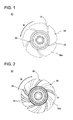
- Fig. 1 is a front view of the axial flow fan of the present embodiment.
- Fig. 2 is a rear view of the axial flow fan of the present embodiment.
- Fig. 3 is a schematic side view that illustrates a state where a part of the axial flow fan of the present embodiment is cut.
- Figs. 4A to 4C are a top view, a bottom view and a rear view of a blade in the axial flow fan of the present embodiment.
- an axial flow fan 100 of the present embodiment includes an impeller 10 attached to a rotation shaft of a rotation driving device (not illustrated), and a venturi casing 41 that surrounds an outer circumference in a radial direction of the impeller 10.
- the venturi casing 41 is a member that constitutes a major part of a fan frame 40.
- the venturi casing 41 is a member of a cylindrical body shape that partitions and forms a wind tunnel as a passage of the wind caused by the impeller 10. Openings of both ends in an axial direction of the venturi casing 41 each serve as a suction port 42 and a discharge port 43.
- flange portions 44 and 45 for fixing the fan frame 40 to an electronic device or the like are provided.
- the flange portions 44 and 45 are square-shaped attachment members that continue with an outer circumferential wall of the venturi casing 41. In four corners of each of the flange portions 44 and 45, screw holes (not illustrated) for screwing with attaching screws are formed.
- the fan frame 40 including the venturi casing 41 and the flange portions 44 and 45 are formed by aluminum or aluminum alloy, other metallic materials, a thermoplastic synthetic resin or the like may be used, without being limited to the described material.
- the impeller 10 includes a hub 20 serving as a rotation center, and a plurality of blades 30 integrally attached to the outer circumference of the hub 20.
- the hub 20 is a cup-like member provided in the central portion of the impeller 10.
- a rotor yoke of a motor (not illustrated) as a rotation driving device of the impeller 10 is fitted into the hub 20.
- a base portion of the motor is supported by the fan frame 40.
- the plurality of blades 30 is integrally and radially attached around the hub 20 serving as the rotation center.
- the impeller 10 in the present embodiment includes five blades 30, the number of the blades 30 is not limited to five.
- the hub 20 and the blade 30 are formed by the thermoplastic synthetic resin, the materials thereof are not limited to the described materials.
- the thermoplastic synthetic resin there are resins including polyethylene (PE), polypropylene (PP), polystyrene (PS), polyvinyl chloride (PVC), polycarbonate (PC), polymethylmethacrylate (PMMA), acrylonitrile-butadiene-styrene (ABS), PC/ABS, polyamide (PA), and polyoxymethylene (POM).
- Each blade 30 has an airfoil shape.
- Each blade 30 is integrally attached to the hub 20 so that a leading end side (a protruding side) of each blade 30 of the airfoil shape is located on the front side in the rotation direction R of the impeller 10.
- Abase endportion (an inner circumferential endportion) of each blade 30 is attached to the hub 20 so as to be inclined with respect to an axial direction of the rotation shaft. Specifically, each blade 30 is attached to the hub 20 in an inclined manner so that a front edge portion 31 in the rotation direction of the blade 30 is located on a head portion side of the hub 20 and a rear edge portion 32 thereof is located on an opening side of the hub 20 (see Fig. 3 ).
- the impeller 10 is placed in the venturi casing 41 so that a front side of each blade 30 serves as a suction port 42 side and a rear side thereof serves as a discharge port 43 side.
- the front side of each blade 30 serves as a negative pressure surface 30a
- the rear side thereof serves as a positive pressure surface 30b.
- the axial flow fan 100 of the present embodiment is configured so that the positive pressure surface 30b of each blade 30 is formed with a plurality of curved step portions 33.
- the plurality of curved step portions 33 is formed only on the positive pressure surface 30b of each blade 30, and the negative pressure surface 30a is formed by the normal smooth surface.
- Fig. 4A is a top view of the outer circumference surface of the blade
- Fig. 4B is a bottom view of an inner circumferential surface (a proximal end surface) of the blade
- Fig. 4C is a rear view of the blade.
- each step portion 33 is formed so as to comply with the curved shape of the front edge portion 31 of the blade 30.
- Each step portion 33 is extended and curved from the base end portion (the inner circumferential portion) of each blade 30 up to the outer circumferential portion, in the positive pressure surface 30b of each blade 30.
- a curvature of the plurality of step portions 33 is formed to be smaller than a curvature of the front edge portion 31 of the blade 30 and to be greater than the curvature of the rear edge portion 32.
- two step portions 33a and 33b are provide on the positive pressure surface 30b of each blade 30.
- the curvature of the step portion 33b located on the rear edge portion 32 side of the blade 30 is set to be smaller than the curvature of the step portion 33a located on the front edge portion 31 side.
- step portions 33a and 33b are provided on the positive pressure surface 30b of each blade 30, the number of the step portions is not limited to two.
- the thickness of the positive pressure surface 30b gradually increases from the front edge portion 31, and rapidly decreases compared to the degree of the increase via the step portion 33a.
- the thickness rapidly decreased via the step portion 33a gradually increases again, rapidly decreases compared to the degree of the increase via the step portion 33b, and then reaches the rear edge portion 32. That is, the cross-sectional shape of the positive pressure surface 30b of the blade 30 progressively repeats a shape in which the thickness smoothly increases from the front edge portion 31 side of the blade 30 and the thickness rapidly decreases via the step portion 33.
- the negative pressure surface 30a of each blade 30 is formed by the normal smooth surface.
- the cross-sectional shape of each blade 30 has a shape as if two streamlines are arranged in series from the front edge portion 31 side toward the rear edge portion 32 side.
- each blade 30 has a shape as if the streamlines depending on the number of the step portions 33 are arranged in series.
- the axial flow fan 100 is attached to a case or the like of an electronic device by screwing with an attachment screw (not illustrated) to a suction side flange portion 44 or a discharge side flange portion 45.
- an attachment screw (not illustrated)
- the suction side flange portion 44 is attached to the fan attachment portion of the inner surface of the case of the PC or the like.
- the discharge side flange portion 45 is attached to a peripheral portion of the opening portion of an inner wall of a building.
- the axial flow fan 100 of the present embodiment As a cooling fan for a server, in the venturi casing 41, the negative pressure surface 30a of each blade 30 of the impeller 10 faces the outside of the case of the server, and the positive pressure surface 30b thereof faces the inside of the case.
- the impeller 10 of the axial flow fan 100 rotates, and the outside air is taken into the case to air-cool an electronic device such as a hard disk (HDD).
- HDD hard disk
- the outside air sucked from the suction port 42 of the axial flow fan 100 is discharged into the case through the discharge port 43 from between the blade 30 of the impeller 10 and the venturi casing 41.
- the axial flow fan 100 of the present embodiment is formed with a plurality of curved step portions 33 on the positive pressure surface 30b of each blade 30.
- Each step portion 33 is curved so as to comply with the curved shape of the front edge portion 31 in the rotation direction of each blade 30.
- Each step portion 33 is extended and curved up from the base end portion (the inner circumferential portion) of each blade 30 to the outer circumferential portion thereof, in the positive pressure surface 30b of each blade 30.
- the step portion 33b located on the rear edge portion 32 side of the blade 30 is curved so that the curvature thereof is reduced compared to the step portion 33a located on the front edge portion 31 side.
- the cross-sectional shape of the positive pressure surface 30b of the blade 30 progressively repeats a shape in which the thickness thereof smoothly increases from the front edge portion 31 side of the blade 30 and the thickness thereof rapidly decreases via the step portion 33.
- the cross-sectional shape of the blade 30 has a shape as if the streamlined blades are arranged in series from the front edge portion 31 side toward the rear edge portion 32 side.
- the blowing characteristics of the axial flow fan 100 of the present embodiment having the above-mentioned blade structure were confirmed by a comparison with the structure of the related art, by manufacturing and driving an experimental model of the axial flow fan 100 of the present embodiment.
- the axial flow fan of the structure of the related art includes the same five blades as the present embodiment, and includes an impeller in which the negative pressure surface and the positive pressure surface of each blade are formed by the smooth surface.
- Fig. 5 is a diagram that describes the blowing characteristics of the experimental model of the axial flow fan of the present embodiment.
- the blowing characteristics were measured about a rotary speed, a maximum wind quantity, a maximum static pressure, a sound pressure level, electric power consumption,static pressure efficiency, and blade efficiency.
- Fig. 5A is a diagram that describes a relationship between the wind quantity and the electric power consumption of the axial flow fan of the present embodiment by the comparison with the structure of the related art.
- Fig. 5A relative curved lines between the wind quantity and the static pressure of the axial flow fan of the present embodiment and the axial flow fan having the structure of the related art are combined with each other.
- Fig. 5B is a diagram for describing the relationship between the wind quantity and the static pressure efficiency of the axial flow fan of the present embodiment by the comparison with the structure of the related art.
- Fig. 5B relative curved lines between the wind quantity and the static pressure of the axial flow fan of the present embodiment and the axial flow fan having the structure of the related art are combined with each other.
- the improvement in the maximum static pressure efficiency of about 5.8 % was obtained compared to the axial flow fan having the structure of the related art. Furthermore, in the axial flow fan of the present embodiment, the improvement in the maximum blade efficiency of about 7.5% was obtained compared to the axial flow fan having the structure of the related art.
- cooling fans the axial flow fans
- the power source of a lot of cooling fans are normally supplied from a single power source device stored in the case, the load to the power source device is great.
- the axial flow fan 100 of the present embodiment has the advantageous effect that can reduce the electric power consumption of the respective cooling fans, and can greatly reduce the load to the electric power device as a whole of the cooling fans.
- the positive pressure surface of the blade of the axial flow fan is formed with the curved step portion in the above-mentioned embodiments
- the present invention can also be applied to a positive pressure surface of a blade of another type fan including a sirocco fan.
Landscapes
- Engineering & Computer Science (AREA)
- Mechanical Engineering (AREA)
- General Engineering & Computer Science (AREA)
- Structures Of Non-Positive Displacement Pumps (AREA)
Abstract
Description
- The present invention relates to an axial flow fan in which a shape of a positive pressure surface of a blade of an impeller is improved.
- The axial flow fan includes a plurality of blades in a radial shape on an outer circumference of a hub serving as a rotation center. Since the axial flow fan has a simple structure, the axial flow fan is widely used in a personal computer (PC), a cooling fan for a server, a ventilation fan or the like.
- Generally, the axial flow fan has blowing characteristics in which a wind quantity is high and a static pressure is low. In order to improve the blowing characteristics of the axial flow fan to reduce noise, various schemes have been performed on the structure of the blades.
- As a technique related to the blade structure of the axial flow fan, an axial flow fan is disclosed in which a plurality of blades is included on an outer circumference of a hub serving as a rotation center, a plurality of dimples is formed on a negative pressure surface of each blade, and a relationship of 0.15 ≤ d / φ ≤ 0.3 is set when assuming a depth of the dimple to d and a hole diameter of the dimple to φ (for example, see
JP 5-332294 A - The technique of
JP 5-332294 A - Furthermore, an axial flow fan is disclosed which is formed by providing a plurality of protrusions on a pressing surface of the blade, and by forming a streamlined blade shape by a surface formed by joining tops of the protrusions and the negative pressure surface of the blade (for example,
JP 11-37092 A - The technique of
JP 11-37092 A - However, according to the techniques of
JP 5-332294 A JP 11-37092 A - Recently, along with the maintenance promotion of the internet and the infrastructure, a large server has spread. A plurality of about forty cooling fans is attached to the casing of the large server. A power source of the plurality of cooling fans is normally supplied from a single power source device stored in the casing, and thus load to the power source device is great. Thus, when the electric power consumption of each of the cooling fans can be lowered even a little, it is possible to greatly lower the load to the power source device as a whole of the cooling fans.
- The present invention was made in view of the above-mentioned circumstances, and an object thereof is to provide an axial flow fan capable of improving the blowing efficiency and the static pressure efficiency and reducing the electric power consumption.
- In order to achieve the above-mentioned object, there is provided an axial flow fan that includes an impeller, a hub of which is attached to a rotation shaft of a rotation driving device; and a venturi casing that surrounds an outer circumference in a radial direction of the impeller and includes a suction port and a discharge port facing each other in an axial direction of the rotation shaft.
- Positive pressure surfaces of a plurality of blades integrally attached to the hub have a plurality of step portions that is curved so as to comply with a curved shape of a front edge portion in the rotation direction of the blade.
- The axial flow fan according to the present invention is configured so that the positive pressure surfaces of each blade have the plurality of step portions. Each of the step portions is curved so as to comply with the curved shape of the front edge portion in the rotation direction of the blade.
- Accordingly, it is considered that a discharge flow between the positive pressure surface of each blade and the venturi casing forms a vortex flow in a rear hollow in the rotation direction of each of the curved step portions. According to the present invention, since the rear discharge flow passes on the phased vortex flow formed by the plurality of step portions, the blowing efficiency and the static pressure efficiency of the axial flow fan can be improved, and the electric power consumption can be reduced.
-
-
Fig. 1 is a front view of an axial flow fan of the present embodiment; -
Fig. 2 is a rear view of the axial flow fan of the present embodiment; -
Fig. 3 is a schematic side view that illustrates a state where a part of the axial flow fan of the present embodiment is cut; -
Figs. 4A to 4C are a top view, a bottom view and a rear view of a blade in the axial flow fan of the present embodiment; and -
Figs. 5A and 5B are diagrams that describe blowing characteristics of an experimental model of the axial flow fan of the present embodiment. - Hereinafter, an axial flow fan of the present embodiment will be described referring to the drawings.
- The axial flow fan of the present embodiment includes a plurality of step portions that is curved so as to comply with a curved shape of a front edge portion in a rotation direction of the blade, on positive pressure surfaces of the plurality of blades integrally attached to a hub. According to the present embodiment, a rear discharge flow passes on a phased vortex flow formed by the plurality of step portions. Thus, an axial flow fan is realized which is able to improve the blowing efficiency and the static pressure efficiency, and reduce the electric power consumption.
- First, a configuration of the axial flow fan of the present embodiment will be described referring to
Figs. 1 to 3 .Fig. 1 is a front view of the axial flow fan of the present embodiment.Fig. 2 is a rear view of the axial flow fan of the present embodiment.Fig. 3 is a schematic side view that illustrates a state where a part of the axial flow fan of the present embodiment is cut.Figs. 4A to 4C are a top view, a bottom view and a rear view of a blade in the axial flow fan of the present embodiment. - As illustrated in
Fig. 3 , anaxial flow fan 100 of the present embodiment includes animpeller 10 attached to a rotation shaft of a rotation driving device (not illustrated), and aventuri casing 41 that surrounds an outer circumference in a radial direction of theimpeller 10. - The
venturi casing 41 is a member that constitutes a major part of afan frame 40. Theventuri casing 41 is a member of a cylindrical body shape that partitions and forms a wind tunnel as a passage of the wind caused by theimpeller 10. Openings of both ends in an axial direction of theventuri casing 41 each serve as asuction port 42 and adischarge port 43. - On peripheries of a suction side and a discharge side of the
venturi casing 41,flange portions fan frame 40 to an electronic device or the like are provided. Theflange portions venturi casing 41. In four corners of each of theflange portions - In addition, although the
fan frame 40 including theventuri casing 41 and theflange portions - The
impeller 10 includes ahub 20 serving as a rotation center, and a plurality ofblades 30 integrally attached to the outer circumference of thehub 20. - The
hub 20 is a cup-like member provided in the central portion of theimpeller 10. A rotor yoke of a motor (not illustrated) as a rotation driving device of theimpeller 10 is fitted into thehub 20. A base portion of the motor is supported by thefan frame 40. - As illustrated in
Fig. 1 , the plurality ofblades 30 is integrally and radially attached around thehub 20 serving as the rotation center. Although theimpeller 10 in the present embodiment includes fiveblades 30, the number of theblades 30 is not limited to five. Although thehub 20 and theblade 30 are formed by the thermoplastic synthetic resin, the materials thereof are not limited to the described materials. As the thermoplastic synthetic resin, there are resins including polyethylene (PE), polypropylene (PP), polystyrene (PS), polyvinyl chloride (PVC), polycarbonate (PC), polymethylmethacrylate (PMMA), acrylonitrile-butadiene-styrene (ABS), PC/ABS, polyamide (PA), and polyoxymethylene (POM). - Each
blade 30 has an airfoil shape. Eachblade 30 is integrally attached to thehub 20 so that a leading end side (a protruding side) of eachblade 30 of the airfoil shape is located on the front side in the rotation direction R of theimpeller 10. - Abase endportion (an inner circumferential endportion) of each
blade 30 is attached to thehub 20 so as to be inclined with respect to an axial direction of the rotation shaft. Specifically, eachblade 30 is attached to thehub 20 in an inclined manner so that afront edge portion 31 in the rotation direction of theblade 30 is located on a head portion side of thehub 20 and arear edge portion 32 thereof is located on an opening side of the hub 20 (seeFig. 3 ). - As illustrated in
Figs. 1 to 3 , theimpeller 10 is placed in theventuri casing 41 so that a front side of eachblade 30 serves as asuction port 42 side and a rear side thereof serves as adischarge port 43 side. Thus, in theaxial flow fan 100, the front side of eachblade 30 serves as anegative pressure surface 30a, and the rear side thereof serves as apositive pressure surface 30b. - The
axial flow fan 100 of the present embodiment is configured so that thepositive pressure surface 30b of eachblade 30 is formed with a plurality ofcurved step portions 33. The plurality ofcurved step portions 33 is formed only on thepositive pressure surface 30b of eachblade 30, and thenegative pressure surface 30a is formed by the normal smooth surface. -
Fig. 4A is a top view of the outer circumference surface of the blade,Fig. 4B is a bottom view of an inner circumferential surface (a proximal end surface) of the blade, andFig. 4C is a rear view of the blade. - As illustrated in
Figs. 2 to 4C , eachstep portion 33 is formed so as to comply with the curved shape of thefront edge portion 31 of theblade 30. Eachstep portion 33 is extended and curved from the base end portion (the inner circumferential portion) of eachblade 30 up to the outer circumferential portion, in thepositive pressure surface 30b of eachblade 30. A curvature of the plurality ofstep portions 33 is formed to be smaller than a curvature of thefront edge portion 31 of theblade 30 and to be greater than the curvature of therear edge portion 32. In the present embodiment, twostep portions positive pressure surface 30b of eachblade 30. The curvature of thestep portion 33b located on therear edge portion 32 side of theblade 30 is set to be smaller than the curvature of thestep portion 33a located on thefront edge portion 31 side. - In the present embodiment, although two
step portions positive pressure surface 30b of eachblade 30, the number of the step portions is not limited to two. - As illustrated in
Figs. 4A and 4B , on a cross section of eachblade 30, the thickness of thepositive pressure surface 30b gradually increases from thefront edge portion 31, and rapidly decreases compared to the degree of the increase via thestep portion 33a. In addition, the thickness rapidly decreased via thestep portion 33a gradually increases again, rapidly decreases compared to the degree of the increase via thestep portion 33b, and then reaches therear edge portion 32. That is, the cross-sectional shape of thepositive pressure surface 30b of theblade 30 progressively repeats a shape in which the thickness smoothly increases from thefront edge portion 31 side of theblade 30 and the thickness rapidly decreases via thestep portion 33. - Meanwhile, as mentioned above, the
negative pressure surface 30a of eachblade 30 is formed by the normal smooth surface. When observing the cross-sectional shape of thepositive pressure surface 30b and the cross-sectional shape of thenegative pressure surface 30a of theblade 30 entirely and together, the cross-sectional shape of eachblade 30 has a shape as if two streamlines are arranged in series from thefront edge portion 31 side toward therear edge portion 32 side. - In addition, when the number of the
step portions 33 is equal to or greater than three, the cross-sectional shape of eachblade 30 has a shape as if the streamlines depending on the number of thestep portions 33 are arranged in series. - Next, the operation of the
axial flow fan 100 of the present embodiment will be described referring toFigs. 1 to 5B . - As illustrated in
Fig. 3 , theaxial flow fan 100 is attached to a case or the like of an electronic device by screwing with an attachment screw (not illustrated) to a suctionside flange portion 44 or a dischargeside flange portion 45. For example, when using theaxial flow fan 100 of the present embodiment as a cooling fan for a PC and a server, the suctionside flange portion 44 is attached to the fan attachment portion of the inner surface of the case of the PC or the like. Furthermore, when using theaxial flow fan 100 of the present embodiment as a ventilation fan, the dischargeside flange portion 45 is attached to a peripheral portion of the opening portion of an inner wall of a building. - When using the
axial flow fan 100 of the present embodiment as a cooling fan for a server, in theventuri casing 41, thenegative pressure surface 30a of eachblade 30 of theimpeller 10 faces the outside of the case of the server, and thepositive pressure surface 30b thereof faces the inside of the case. During operation of the server, theimpeller 10 of theaxial flow fan 100 rotates, and the outside air is taken into the case to air-cool an electronic device such as a hard disk (HDD). - The outside air sucked from the
suction port 42 of theaxial flow fan 100 is discharged into the case through thedischarge port 43 from between theblade 30 of theimpeller 10 and theventuri casing 41. - The
axial flow fan 100 of the present embodiment is formed with a plurality ofcurved step portions 33 on thepositive pressure surface 30b of eachblade 30. Eachstep portion 33 is curved so as to comply with the curved shape of thefront edge portion 31 in the rotation direction of eachblade 30. Eachstep portion 33 is extended and curved up from the base end portion (the inner circumferential portion) of eachblade 30 to the outer circumferential portion thereof, in thepositive pressure surface 30b of eachblade 30. Thestep portion 33b located on therear edge portion 32 side of theblade 30 is curved so that the curvature thereof is reduced compared to thestep portion 33a located on thefront edge portion 31 side. - The cross-sectional shape of the
positive pressure surface 30b of theblade 30 progressively repeats a shape in which the thickness thereof smoothly increases from thefront edge portion 31 side of theblade 30 and the thickness thereof rapidly decreases via thestep portion 33. Thus, the cross-sectional shape of theblade 30 has a shape as if the streamlined blades are arranged in series from thefront edge portion 31 side toward therear edge portion 32 side. - As illustrated in
Figs. 5A and 5B , the blowing characteristics of theaxial flow fan 100 of the present embodiment having the above-mentioned blade structure were confirmed by a comparison with the structure of the related art, by manufacturing and driving an experimental model of theaxial flow fan 100 of the present embodiment. The axial flow fan of the structure of the related art includes the same five blades as the present embodiment, and includes an impeller in which the negative pressure surface and the positive pressure surface of each blade are formed by the smooth surface. -
Fig. 5 is a diagram that describes the blowing characteristics of the experimental model of the axial flow fan of the present embodiment. In addition, the blowing characteristics were measured about a rotary speed, a maximum wind quantity, a maximum static pressure, a sound pressure level, electric power consumption,static pressure efficiency, and blade efficiency. - First,
Fig. 5A is a diagram that describes a relationship between the wind quantity and the electric power consumption of the axial flow fan of the present embodiment by the comparison with the structure of the related art. InFig. 5A , relative curved lines between the wind quantity and the static pressure of the axial flow fan of the present embodiment and the axial flow fan having the structure of the related art are combined with each other. - As illustrated in
Fig. 5A , as the wind quantity of the axial flow fan increases, the static pressure gradually decreases. Furthermore, when increasing the wind quantity of the axial flow fan, the electric power consumption gently rises and then decreases while drawing a descent curve. - When combining the relative curved lines between the wind quantity and the static pressure of the axial flow fan of the present embodiment and the axial flow fan having the structure of the related art, in the axial flow fan of the present embodiment, the reduction of the minimum electric power consumption [W] of about 12.7 % was obtained compared to the axial flow fan having the structure of the related art.
- Next,
Fig. 5B is a diagram for describing the relationship between the wind quantity and the static pressure efficiency of the axial flow fan of the present embodiment by the comparison with the structure of the related art. InFig. 5B , relative curved lines between the wind quantity and the static pressure of the axial flow fan of the present embodiment and the axial flow fan having the structure of the related art are combined with each other. - As illustrated in
Fig. 5B , as the wind quantity of the axial flow fan increases, the static pressure gradually decreases. Furthermore, when increasing the wind quantity of the axial flow fan, the static pressure efficiency changes while drawing a mountain-like curve. - When combining the relative curved lines between the wind quantity and the static pressure of the axial flow fan of the present embodiment and the axial flow fan having the structure of the related art, in the axial flow fan of the present embodiment, the improvement in the maximum static pressure efficiency of about 5.8 % was obtained compared to the axial flow fan having the structure of the related art. Furthermore, in the axial flow fan of the present embodiment, the improvement in the maximum blade efficiency of about 7.5% was obtained compared to the axial flow fan having the structure of the related art.
- From the measurement result of the blowing characteristics of the experimental model of
Figs. 5A and 5B , it is considered that the discharge flow between thepositive pressure surface 30b of eachblade 30 and theventuri casing 41 forms a vortex flow in the rear hollow in the rotation direction of the respectivecurved step portions axial flow fan 100 of the present embodiment, the rear discharge flow passes on the phased vortex flow formed by the plurality ofstep portions - Particularly, in the case of the large server, since there are many numbers of the incorporated HDD, about forty cooling fans (the axial flow fans) 100 are attached. Since the power source of a lot of cooling fans are normally supplied from a single power source device stored in the case, the load to the power source device is great.
- The
axial flow fan 100 of the present embodiment has the advantageous effect that can reduce the electric power consumption of the respective cooling fans, and can greatly reduce the load to the electric power device as a whole of the cooling fans. - Although the preferred embodiments of the present invention have been described above, the embodiments are examples for describing the present invention, and the scope of the present invention is not intended to be limited only to the embodiments. The present invention can be carried out in various aspects that are different from the above-mentioned embodiments, within the scope that does not depart from the gist thereof.
- Furthermore, although the positive pressure surface of the blade of the axial flow fan is formed with the curved step portion in the above-mentioned embodiments, the present invention can also be applied to a positive pressure surface of a blade of another type fan including a sirocco fan.
Claims (6)
- An axial flow fan comprising:an impeller, a hub of which is attached to a rotation shaft of a rotation driving device; anda plurality of blades integrally attached to the hub,wherein a positive pressure surface of the plurality of blades includes a plurality of step portions that is curved so as to comply with a curved shape of a front edge portion in a rotation direction of the blades.
- An axial flow fan comprising:an impeller, a hub of which is attached to a rotation shaft of a rotation driving device; anda venturi casing that surrounds an outer circumference in a radial direction of the impeller, and includes a suction port and a discharge port facing each other in an axial direction of the rotation shaft,wherein a positive pressure surface of the plurality of blades integrally attached to the hub includes a plurality of step portions that is curved so as to comply with a curved shape of a front edge portion in a rotation direction of the blades.
- The axial flow fan according to claim 1 or 2,
wherein the respective step portions are extended and curved from an inner circumferential portion of each blade to an outer circumferential portion thereof, in the positive pressure surface of each blade. - The axial flow fan according to claim 1 or 2,
wherein the step portion located on a rear edge portion side of the blade is curved so that a curvature thereof is reduced compared to a step portion located on a front edge portion side. - The axial flow fan according to claim 1 or 2,
wherein a cross-sectional shape of the positive pressure surface of the blade progressively repeats a shape in which a thickness smoothly increases from the front edge portion side of the blade and rapidly decreases via the step portion. - The axial flow fan according to claim 1 or 2,
wherein the cross-sectional shape of the blade includes a shape in which streamlined blades are arranged in series from the front edge portion side toward the rear edge portion side.
Applications Claiming Priority (1)
| Application Number | Priority Date | Filing Date | Title |
|---|---|---|---|
| JP2012081465A JP2013209956A (en) | 2012-03-30 | 2012-03-30 | Axial flow fan |
Publications (3)
| Publication Number | Publication Date |
|---|---|
| EP2644902A2 true EP2644902A2 (en) | 2013-10-02 |
| EP2644902A3 EP2644902A3 (en) | 2016-05-11 |
| EP2644902B1 EP2644902B1 (en) | 2019-11-20 |
Family
ID=48013787
Family Applications (1)
| Application Number | Title | Priority Date | Filing Date |
|---|---|---|---|
| EP13160940.6A Active EP2644902B1 (en) | 2012-03-30 | 2013-03-25 | Axial flow fan |
Country Status (6)
| Country | Link |
|---|---|
| US (1) | US9714659B2 (en) |
| EP (1) | EP2644902B1 (en) |
| JP (1) | JP2013209956A (en) |
| KR (1) | KR20130111458A (en) |
| CN (1) | CN103362868B (en) |
| TW (1) | TWI631283B (en) |
Cited By (1)
| Publication number | Priority date | Publication date | Assignee | Title |
|---|---|---|---|---|
| CN105889128A (en) * | 2016-05-25 | 2016-08-24 | 珠海格力电器股份有限公司 | Centrifugal fan blade, outer rotor fan and air conditioner |
Families Citing this family (9)
| Publication number | Priority date | Publication date | Assignee | Title |
|---|---|---|---|---|
| USD727490S1 (en) * | 2013-02-25 | 2015-04-21 | Wellington Drive Technologies Limited | Fan blade |
| USD750211S1 (en) | 2014-02-27 | 2016-02-23 | Mitsubishi Electric Corporation | Propeller fan |
| US9857209B2 (en) * | 2015-03-06 | 2018-01-02 | Sanyo Denki Co., Ltd. | Measurement device for measuring airflow volume and ventilation resistance of wind-blowing apparatus |
| MX392790B (en) * | 2015-04-08 | 2025-03-24 | Horton Inc | FAN BLADE SURFACE CHARACTERISTICS. |
| USD901669S1 (en) | 2017-09-29 | 2020-11-10 | Carrier Corporation | Contoured fan blade |
| CN112664465B (en) * | 2019-10-16 | 2022-09-13 | 宏碁股份有限公司 | Axial flow fan |
| TWI747586B (en) * | 2020-10-30 | 2021-11-21 | 奇鋐科技股份有限公司 | Blade wheel structure for axial fan |
| CN115405538A (en) * | 2021-05-28 | 2022-11-29 | 冷王公司 | High-efficiency axial fan |
| TWI871703B (en) * | 2023-07-19 | 2025-02-01 | 宏碁股份有限公司 | Axial-flow heat-dissipation fan |
Family Cites Families (25)
| Publication number | Priority date | Publication date | Assignee | Title |
|---|---|---|---|---|
| JPS5528710U (en) * | 1978-08-11 | 1980-02-25 | ||
| JPS5528710A (en) * | 1978-08-19 | 1980-02-29 | Hokuetsu Tanso Kogyo Kk | Deodorizing method |
| JPS57153998A (en) * | 1981-03-20 | 1982-09-22 | Aisin Seiki Co Ltd | Flexible fan |
| JPS5994998U (en) * | 1982-12-17 | 1984-06-27 | 三菱重工業株式会社 | Anti-noise marine propeller |
| US4971520A (en) * | 1989-08-11 | 1990-11-20 | Airflow Research And Manufacturing Corporation | High efficiency fan |
| DE9006174U1 (en) * | 1990-05-31 | 1991-10-10 | Papst-Motoren GmbH & Co KG, 7742 St Georgen | Axial fan with cylindrical outer casing |
| JP2776146B2 (en) | 1992-05-29 | 1998-07-16 | ダイキン工業株式会社 | Axial fan |
| JPH0687692U (en) * | 1993-05-29 | 1994-12-22 | 有限会社フジヤス産業 | Deodorizer |
| JPH07119695A (en) * | 1993-10-27 | 1995-05-09 | Matsushita Seiko Co Ltd | Axial fan |
| JPH07293495A (en) * | 1994-04-20 | 1995-11-07 | Mitsubishi Electric Corp | Blower |
| JP3082586B2 (en) * | 1994-09-12 | 2000-08-28 | ダイキン工業株式会社 | Propeller fan |
| US5624234A (en) * | 1994-11-18 | 1997-04-29 | Itt Automotive Electrical Systems, Inc. | Fan blade with curved planform and high-lift airfoil having bulbous leading edge |
| JP3726433B2 (en) | 1997-07-18 | 2005-12-14 | 株式会社富士通ゼネラル | Axial fan |
| KR100761152B1 (en) * | 2001-06-12 | 2007-09-21 | 한라공조주식회사 | Axial flow fan |
| JP3978083B2 (en) | 2001-06-12 | 2007-09-19 | 漢拏空調株式会社 | Axial fan |
| CN2554409Y (en) * | 2002-01-18 | 2003-06-04 | 东莞清溪新乔电脑厂 | a wind impeller |
| JP4243105B2 (en) * | 2003-01-10 | 2009-03-25 | パナソニックエコシステムズ株式会社 | Impeller |
| JP2004317065A (en) * | 2003-04-18 | 2004-11-11 | Hitachi Home & Life Solutions Inc | Air conditioner |
| TWI256444B (en) * | 2004-05-06 | 2006-06-11 | Sunonwealth Electr Mach Ind Co | Air outlet structure for an axial-flow fan |
| CN100554702C (en) * | 2006-06-09 | 2009-10-28 | 日本电产株式会社 | Axial fan |
| JP2008014302A (en) | 2006-06-09 | 2008-01-24 | Nippon Densan Corp | Axial flow fan |
| CN201382021Y (en) * | 2009-03-25 | 2010-01-13 | 广东美的电器股份有限公司 | Axial flow wind wheel |
| JP5079063B2 (en) * | 2010-08-25 | 2012-11-21 | 三菱電機株式会社 | Propeller, blower and heat pump device |
| USD663689S1 (en) * | 2011-06-01 | 2012-07-17 | Lee Lawrence K | Windmill blade |
| USD668606S1 (en) * | 2011-09-30 | 2012-10-09 | Lee Lawrence K | Windmill blade |
-
2012
- 2012-03-30 JP JP2012081465A patent/JP2013209956A/en active Pending
-
2013
- 2013-03-08 TW TW102108344A patent/TWI631283B/en active
- 2013-03-25 EP EP13160940.6A patent/EP2644902B1/en active Active
- 2013-03-26 CN CN201310098880.6A patent/CN103362868B/en active Active
- 2013-03-28 US US13/852,868 patent/US9714659B2/en active Active
- 2013-03-29 KR KR20130034664A patent/KR20130111458A/en not_active Withdrawn
Cited By (1)
| Publication number | Priority date | Publication date | Assignee | Title |
|---|---|---|---|---|
| CN105889128A (en) * | 2016-05-25 | 2016-08-24 | 珠海格力电器股份有限公司 | Centrifugal fan blade, outer rotor fan and air conditioner |
Also Published As
| Publication number | Publication date |
|---|---|
| EP2644902B1 (en) | 2019-11-20 |
| TW201344062A (en) | 2013-11-01 |
| EP2644902A3 (en) | 2016-05-11 |
| US9714659B2 (en) | 2017-07-25 |
| JP2013209956A (en) | 2013-10-10 |
| TWI631283B (en) | 2018-08-01 |
| CN103362868A (en) | 2013-10-23 |
| KR20130111458A (en) | 2013-10-10 |
| US20140003933A1 (en) | 2014-01-02 |
| CN103362868B (en) | 2018-10-02 |
Similar Documents
| Publication | Publication Date | Title |
|---|---|---|
| US9714659B2 (en) | Axial flow fan | |
| US9709073B2 (en) | Centrifugal fan | |
| US10605269B2 (en) | Fan comprising an impeller with blades | |
| US8961124B2 (en) | Axial fan | |
| JP5705945B1 (en) | Centrifugal fan | |
| JP5809859B2 (en) | Centrifugal fan | |
| US9194398B2 (en) | Centrifugal fan | |
| US9234524B2 (en) | Boundary layer controlled logarithmic spiral blade | |
| US20100054931A1 (en) | Serial axial fan | |
| KR20130058605A (en) | Axial-flow fan | |
| JP2013076335A (en) | Centrifugal fan | |
| KR20120061970A (en) | Propeller fan, molding die, and fluid feed device | |
| CN201218235Y (en) | Fan blade device of heat radiation fan | |
| US9394920B2 (en) | Centrifugal fan | |
| CN204783822U (en) | Centrifugal aerator | |
| US8113782B2 (en) | Impeller structure of blower | |
| JP6282720B2 (en) | Centrifugal fan | |
| KR20120023319A (en) | A turbo fan for air conditioner | |
| JPH0121198Y2 (en) | ||
| JP2005133683A (en) | Blower impeller | |
| CN100453824C (en) | Heat radiation fan | |
| JP6113250B2 (en) | Centrifugal fan | |
| JP2014122580A (en) | Multiblade centrifugal fan and multiblade centrifugal air blower including the same | |
| JP2020023952A (en) | Electric blower |
Legal Events
| Date | Code | Title | Description |
|---|---|---|---|
| PUAI | Public reference made under article 153(3) epc to a published international application that has entered the european phase |
Free format text: ORIGINAL CODE: 0009012 |
|
| AK | Designated contracting states |
Kind code of ref document: A2 Designated state(s): AL AT BE BG CH CY CZ DE DK EE ES FI FR GB GR HR HU IE IS IT LI LT LU LV MC MK MT NL NO PL PT RO RS SE SI SK SM TR |
|
| AX | Request for extension of the european patent |
Extension state: BA ME |
|
| PUAL | Search report despatched |
Free format text: ORIGINAL CODE: 0009013 |
|
| AK | Designated contracting states |
Kind code of ref document: A3 Designated state(s): AL AT BE BG CH CY CZ DE DK EE ES FI FR GB GR HR HU IE IS IT LI LT LU LV MC MK MT NL NO PL PT RO RS SE SI SK SM TR |
|
| AX | Request for extension of the european patent |
Extension state: BA ME |
|
| RIC1 | Information provided on ipc code assigned before grant |
Ipc: F04D 29/38 20060101AFI20160407BHEP Ipc: F04D 29/68 20060101ALI20160407BHEP |
|
| STAA | Information on the status of an ep patent application or granted ep patent |
Free format text: STATUS: REQUEST FOR EXAMINATION WAS MADE |
|
| 17P | Request for examination filed |
Effective date: 20161109 |
|
| RBV | Designated contracting states (corrected) |
Designated state(s): AL AT BE BG CH CY CZ DE DK EE ES FI FR GB GR HR HU IE IS IT LI LT LU LV MC MK MT NL NO PL PT RO RS SE SI SK SM TR |
|
| STAA | Information on the status of an ep patent application or granted ep patent |
Free format text: STATUS: EXAMINATION IS IN PROGRESS |
|
| 17Q | First examination report despatched |
Effective date: 20171004 |
|
| GRAP | Despatch of communication of intention to grant a patent |
Free format text: ORIGINAL CODE: EPIDOSNIGR1 |
|
| STAA | Information on the status of an ep patent application or granted ep patent |
Free format text: STATUS: GRANT OF PATENT IS INTENDED |
|
| INTG | Intention to grant announced |
Effective date: 20190718 |
|
| GRAS | Grant fee paid |
Free format text: ORIGINAL CODE: EPIDOSNIGR3 |
|
| RIN1 | Information on inventor provided before grant (corrected) |
Inventor name: INADA, NAOYA Inventor name: WATANABE, JIRO |
|
| GRAA | (expected) grant |
Free format text: ORIGINAL CODE: 0009210 |
|
| STAA | Information on the status of an ep patent application or granted ep patent |
Free format text: STATUS: THE PATENT HAS BEEN GRANTED |
|
| RAP1 | Party data changed (applicant data changed or rights of an application transferred) |
Owner name: SANYO DENKI CO., LTD. |
|
| AK | Designated contracting states |
Kind code of ref document: B1 Designated state(s): AL AT BE BG CH CY CZ DE DK EE ES FI FR GB GR HR HU IE IS IT LI LT LU LV MC MK MT NL NO PL PT RO RS SE SI SK SM TR |
|
| REG | Reference to a national code |
Ref country code: GB Ref legal event code: FG4D |
|
| REG | Reference to a national code |
Ref country code: CH Ref legal event code: EP |
|
| REG | Reference to a national code |
Ref country code: IE Ref legal event code: FG4D |
|
| REG | Reference to a national code |
Ref country code: DE Ref legal event code: R096 Ref document number: 602013063025 Country of ref document: DE |
|
| REG | Reference to a national code |
Ref country code: AT Ref legal event code: REF Ref document number: 1204493 Country of ref document: AT Kind code of ref document: T Effective date: 20191215 |
|
| REG | Reference to a national code |
Ref country code: NL Ref legal event code: MP Effective date: 20191120 |
|
| REG | Reference to a national code |
Ref country code: LT Ref legal event code: MG4D |
|
| PG25 | Lapsed in a contracting state [announced via postgrant information from national office to epo] |
Ref country code: NO Free format text: LAPSE BECAUSE OF FAILURE TO SUBMIT A TRANSLATION OF THE DESCRIPTION OR TO PAY THE FEE WITHIN THE PRESCRIBED TIME-LIMIT Effective date: 20200220 Ref country code: GR Free format text: LAPSE BECAUSE OF FAILURE TO SUBMIT A TRANSLATION OF THE DESCRIPTION OR TO PAY THE FEE WITHIN THE PRESCRIBED TIME-LIMIT Effective date: 20200221 Ref country code: BG Free format text: LAPSE BECAUSE OF FAILURE TO SUBMIT A TRANSLATION OF THE DESCRIPTION OR TO PAY THE FEE WITHIN THE PRESCRIBED TIME-LIMIT Effective date: 20200220 Ref country code: NL Free format text: LAPSE BECAUSE OF FAILURE TO SUBMIT A TRANSLATION OF THE DESCRIPTION OR TO PAY THE FEE WITHIN THE PRESCRIBED TIME-LIMIT Effective date: 20191120 Ref country code: LT Free format text: LAPSE BECAUSE OF FAILURE TO SUBMIT A TRANSLATION OF THE DESCRIPTION OR TO PAY THE FEE WITHIN THE PRESCRIBED TIME-LIMIT Effective date: 20191120 Ref country code: ES Free format text: LAPSE BECAUSE OF FAILURE TO SUBMIT A TRANSLATION OF THE DESCRIPTION OR TO PAY THE FEE WITHIN THE PRESCRIBED TIME-LIMIT Effective date: 20191120 Ref country code: LV Free format text: LAPSE BECAUSE OF FAILURE TO SUBMIT A TRANSLATION OF THE DESCRIPTION OR TO PAY THE FEE WITHIN THE PRESCRIBED TIME-LIMIT Effective date: 20191120 Ref country code: SE Free format text: LAPSE BECAUSE OF FAILURE TO SUBMIT A TRANSLATION OF THE DESCRIPTION OR TO PAY THE FEE WITHIN THE PRESCRIBED TIME-LIMIT Effective date: 20191120 Ref country code: FI Free format text: LAPSE BECAUSE OF FAILURE TO SUBMIT A TRANSLATION OF THE DESCRIPTION OR TO PAY THE FEE WITHIN THE PRESCRIBED TIME-LIMIT Effective date: 20191120 |
|
| PG25 | Lapsed in a contracting state [announced via postgrant information from national office to epo] |
Ref country code: IS Free format text: LAPSE BECAUSE OF FAILURE TO SUBMIT A TRANSLATION OF THE DESCRIPTION OR TO PAY THE FEE WITHIN THE PRESCRIBED TIME-LIMIT Effective date: 20200320 Ref country code: RS Free format text: LAPSE BECAUSE OF FAILURE TO SUBMIT A TRANSLATION OF THE DESCRIPTION OR TO PAY THE FEE WITHIN THE PRESCRIBED TIME-LIMIT Effective date: 20191120 Ref country code: HR Free format text: LAPSE BECAUSE OF FAILURE TO SUBMIT A TRANSLATION OF THE DESCRIPTION OR TO PAY THE FEE WITHIN THE PRESCRIBED TIME-LIMIT Effective date: 20191120 |
|
| PG25 | Lapsed in a contracting state [announced via postgrant information from national office to epo] |
Ref country code: AL Free format text: LAPSE BECAUSE OF FAILURE TO SUBMIT A TRANSLATION OF THE DESCRIPTION OR TO PAY THE FEE WITHIN THE PRESCRIBED TIME-LIMIT Effective date: 20191120 |
|
| PG25 | Lapsed in a contracting state [announced via postgrant information from national office to epo] |
Ref country code: DK Free format text: LAPSE BECAUSE OF FAILURE TO SUBMIT A TRANSLATION OF THE DESCRIPTION OR TO PAY THE FEE WITHIN THE PRESCRIBED TIME-LIMIT Effective date: 20191120 Ref country code: PT Free format text: LAPSE BECAUSE OF FAILURE TO SUBMIT A TRANSLATION OF THE DESCRIPTION OR TO PAY THE FEE WITHIN THE PRESCRIBED TIME-LIMIT Effective date: 20200412 Ref country code: EE Free format text: LAPSE BECAUSE OF FAILURE TO SUBMIT A TRANSLATION OF THE DESCRIPTION OR TO PAY THE FEE WITHIN THE PRESCRIBED TIME-LIMIT Effective date: 20191120 Ref country code: RO Free format text: LAPSE BECAUSE OF FAILURE TO SUBMIT A TRANSLATION OF THE DESCRIPTION OR TO PAY THE FEE WITHIN THE PRESCRIBED TIME-LIMIT Effective date: 20191120 Ref country code: CZ Free format text: LAPSE BECAUSE OF FAILURE TO SUBMIT A TRANSLATION OF THE DESCRIPTION OR TO PAY THE FEE WITHIN THE PRESCRIBED TIME-LIMIT Effective date: 20191120 |
|
| REG | Reference to a national code |
Ref country code: AT Ref legal event code: MK05 Ref document number: 1204493 Country of ref document: AT Kind code of ref document: T Effective date: 20191120 |
|
| REG | Reference to a national code |
Ref country code: DE Ref legal event code: R097 Ref document number: 602013063025 Country of ref document: DE |
|
| PG25 | Lapsed in a contracting state [announced via postgrant information from national office to epo] |
Ref country code: SK Free format text: LAPSE BECAUSE OF FAILURE TO SUBMIT A TRANSLATION OF THE DESCRIPTION OR TO PAY THE FEE WITHIN THE PRESCRIBED TIME-LIMIT Effective date: 20191120 Ref country code: SM Free format text: LAPSE BECAUSE OF FAILURE TO SUBMIT A TRANSLATION OF THE DESCRIPTION OR TO PAY THE FEE WITHIN THE PRESCRIBED TIME-LIMIT Effective date: 20191120 |
|
| PLBE | No opposition filed within time limit |
Free format text: ORIGINAL CODE: 0009261 |
|
| STAA | Information on the status of an ep patent application or granted ep patent |
Free format text: STATUS: NO OPPOSITION FILED WITHIN TIME LIMIT |
|
| 26N | No opposition filed |
Effective date: 20200821 |
|
| PG25 | Lapsed in a contracting state [announced via postgrant information from national office to epo] |
Ref country code: MC Free format text: LAPSE BECAUSE OF FAILURE TO SUBMIT A TRANSLATION OF THE DESCRIPTION OR TO PAY THE FEE WITHIN THE PRESCRIBED TIME-LIMIT Effective date: 20191120 |
|
| REG | Reference to a national code |
Ref country code: CH Ref legal event code: PL |
|
| PG25 | Lapsed in a contracting state [announced via postgrant information from national office to epo] |
Ref country code: PL Free format text: LAPSE BECAUSE OF FAILURE TO SUBMIT A TRANSLATION OF THE DESCRIPTION OR TO PAY THE FEE WITHIN THE PRESCRIBED TIME-LIMIT Effective date: 20191120 Ref country code: SI Free format text: LAPSE BECAUSE OF FAILURE TO SUBMIT A TRANSLATION OF THE DESCRIPTION OR TO PAY THE FEE WITHIN THE PRESCRIBED TIME-LIMIT Effective date: 20191120 Ref country code: AT Free format text: LAPSE BECAUSE OF FAILURE TO SUBMIT A TRANSLATION OF THE DESCRIPTION OR TO PAY THE FEE WITHIN THE PRESCRIBED TIME-LIMIT Effective date: 20191120 |
|
| REG | Reference to a national code |
Ref country code: BE Ref legal event code: MM Effective date: 20200331 |
|
| PG25 | Lapsed in a contracting state [announced via postgrant information from national office to epo] |
Ref country code: LU Free format text: LAPSE BECAUSE OF NON-PAYMENT OF DUE FEES Effective date: 20200325 |
|
| REG | Reference to a national code |
Ref country code: DE Ref legal event code: R082 Ref document number: 602013063025 Country of ref document: DE Representative=s name: HL KEMPNER PATENTANWAELTE, SOLICITORS (ENGLAND, DE Ref country code: DE Ref legal event code: R082 Ref document number: 602013063025 Country of ref document: DE Representative=s name: HL KEMPNER PATENTANWALT, RECHTSANWALT, SOLICIT, DE Ref country code: DE Ref legal event code: R082 Ref document number: 602013063025 Country of ref document: DE Representative=s name: HL KEMPNER PARTG MBB, DE |
|
| PG25 | Lapsed in a contracting state [announced via postgrant information from national office to epo] |
Ref country code: LI Free format text: LAPSE BECAUSE OF NON-PAYMENT OF DUE FEES Effective date: 20200331 Ref country code: IE Free format text: LAPSE BECAUSE OF NON-PAYMENT OF DUE FEES Effective date: 20200325 Ref country code: FR Free format text: LAPSE BECAUSE OF NON-PAYMENT OF DUE FEES Effective date: 20200331 Ref country code: CH Free format text: LAPSE BECAUSE OF NON-PAYMENT OF DUE FEES Effective date: 20200331 Ref country code: IT Free format text: LAPSE BECAUSE OF FAILURE TO SUBMIT A TRANSLATION OF THE DESCRIPTION OR TO PAY THE FEE WITHIN THE PRESCRIBED TIME-LIMIT Effective date: 20191120 |
|
| PG25 | Lapsed in a contracting state [announced via postgrant information from national office to epo] |
Ref country code: BE Free format text: LAPSE BECAUSE OF NON-PAYMENT OF DUE FEES Effective date: 20200331 |
|
| GBPC | Gb: european patent ceased through non-payment of renewal fee |
Effective date: 20200325 |
|
| PG25 | Lapsed in a contracting state [announced via postgrant information from national office to epo] |
Ref country code: GB Free format text: LAPSE BECAUSE OF NON-PAYMENT OF DUE FEES Effective date: 20200325 |
|
| PG25 | Lapsed in a contracting state [announced via postgrant information from national office to epo] |
Ref country code: TR Free format text: LAPSE BECAUSE OF FAILURE TO SUBMIT A TRANSLATION OF THE DESCRIPTION OR TO PAY THE FEE WITHIN THE PRESCRIBED TIME-LIMIT Effective date: 20191120 Ref country code: MT Free format text: LAPSE BECAUSE OF FAILURE TO SUBMIT A TRANSLATION OF THE DESCRIPTION OR TO PAY THE FEE WITHIN THE PRESCRIBED TIME-LIMIT Effective date: 20191120 Ref country code: CY Free format text: LAPSE BECAUSE OF FAILURE TO SUBMIT A TRANSLATION OF THE DESCRIPTION OR TO PAY THE FEE WITHIN THE PRESCRIBED TIME-LIMIT Effective date: 20191120 |
|
| PG25 | Lapsed in a contracting state [announced via postgrant information from national office to epo] |
Ref country code: MK Free format text: LAPSE BECAUSE OF FAILURE TO SUBMIT A TRANSLATION OF THE DESCRIPTION OR TO PAY THE FEE WITHIN THE PRESCRIBED TIME-LIMIT Effective date: 20191120 |
|
| PGFP | Annual fee paid to national office [announced via postgrant information from national office to epo] |
Ref country code: DE Payment date: 20260319 Year of fee payment: 14 |