EP2644904B1 - Procédé de commande d'un système de travail à actionnement fluidique - Google Patents
Procédé de commande d'un système de travail à actionnement fluidique Download PDFInfo
- Publication number
- EP2644904B1 EP2644904B1 EP20120002099 EP12002099A EP2644904B1 EP 2644904 B1 EP2644904 B1 EP 2644904B1 EP 20120002099 EP20120002099 EP 20120002099 EP 12002099 A EP12002099 A EP 12002099A EP 2644904 B1 EP2644904 B1 EP 2644904B1
- Authority
- EP
- European Patent Office
- Prior art keywords
- working chamber
- fluid
- volume
- actuator member
- valve device
- Prior art date
- Legal status (The legal status is an assumption and is not a legal conclusion. Google has not performed a legal analysis and makes no representation as to the accuracy of the status listed.)
- Active
Links
Images

Classifications
-
- F—MECHANICAL ENGINEERING; LIGHTING; HEATING; WEAPONS; BLASTING
- F15—FLUID-PRESSURE ACTUATORS; HYDRAULICS OR PNEUMATICS IN GENERAL
- F15B—SYSTEMS ACTING BY MEANS OF FLUIDS IN GENERAL; FLUID-PRESSURE ACTUATORS, e.g. SERVOMOTORS; DETAILS OF FLUID-PRESSURE SYSTEMS, NOT OTHERWISE PROVIDED FOR
- F15B11/00—Servomotor systems without provision for follow-up action ; Circuits therefor
- F15B11/02—Systems essentially incorporating special features for controlling the speed or the actuating force of an output member
- F15B11/04—Systems essentially incorporating special features for controlling the speed or the actuating force of an output member for controlling the speed
- F15B11/046—Systems essentially incorporating special features for controlling the speed or the actuating force of an output member for controlling the speed depending on the position of the working member
- F15B11/048—Systems essentially incorporating special features for controlling the speed or the actuating force of an output member for controlling the speed depending on the position of the working member with deceleration control
-
- F—MECHANICAL ENGINEERING; LIGHTING; HEATING; WEAPONS; BLASTING
- F15—FLUID-PRESSURE ACTUATORS; HYDRAULICS OR PNEUMATICS IN GENERAL
- F15B—SYSTEMS ACTING BY MEANS OF FLUIDS IN GENERAL; FLUID-PRESSURE ACTUATORS, e.g. SERVOMOTORS; DETAILS OF FLUID-PRESSURE SYSTEMS, NOT OTHERWISE PROVIDED FOR
- F15B11/00—Servomotor systems without provision for follow-up action ; Circuits therefor
- F15B11/06—Servomotor systems without provision for follow-up action ; Circuits therefor involving features specific to the use of a compressible medium, e.g. air, steam
- F15B11/064—Servomotor systems without provision for follow-up action ; Circuits therefor involving features specific to the use of a compressible medium, e.g. air, steam with devices for saving the compressible medium
-
- F—MECHANICAL ENGINEERING; LIGHTING; HEATING; WEAPONS; BLASTING
- F15—FLUID-PRESSURE ACTUATORS; HYDRAULICS OR PNEUMATICS IN GENERAL
- F15B—SYSTEMS ACTING BY MEANS OF FLUIDS IN GENERAL; FLUID-PRESSURE ACTUATORS, e.g. SERVOMOTORS; DETAILS OF FLUID-PRESSURE SYSTEMS, NOT OTHERWISE PROVIDED FOR
- F15B2211/00—Circuits for servomotor systems
- F15B2211/30—Directional control
- F15B2211/305—Directional control characterised by the type of valves
- F15B2211/3056—Assemblies of multiple valves
- F15B2211/30565—Assemblies of multiple valves having multiple valves for a single output member, e.g. for creating higher valve function by use of multiple valves like two 2/2-valves replacing a 5/3-valve
- F15B2211/3057—Assemblies of multiple valves having multiple valves for a single output member, e.g. for creating higher valve function by use of multiple valves like two 2/2-valves replacing a 5/3-valve having two valves, one for each port of a double-acting output member
-
- F—MECHANICAL ENGINEERING; LIGHTING; HEATING; WEAPONS; BLASTING
- F15—FLUID-PRESSURE ACTUATORS; HYDRAULICS OR PNEUMATICS IN GENERAL
- F15B—SYSTEMS ACTING BY MEANS OF FLUIDS IN GENERAL; FLUID-PRESSURE ACTUATORS, e.g. SERVOMOTORS; DETAILS OF FLUID-PRESSURE SYSTEMS, NOT OTHERWISE PROVIDED FOR
- F15B2211/00—Circuits for servomotor systems
- F15B2211/30—Directional control
- F15B2211/305—Directional control characterised by the type of valves
- F15B2211/3056—Assemblies of multiple valves
- F15B2211/30565—Assemblies of multiple valves having multiple valves for a single output member, e.g. for creating higher valve function by use of multiple valves like two 2/2-valves replacing a 5/3-valve
- F15B2211/30575—Assemblies of multiple valves having multiple valves for a single output member, e.g. for creating higher valve function by use of multiple valves like two 2/2-valves replacing a 5/3-valve in a Wheatstone Bridge arrangement (also half bridges)
-
- F—MECHANICAL ENGINEERING; LIGHTING; HEATING; WEAPONS; BLASTING
- F15—FLUID-PRESSURE ACTUATORS; HYDRAULICS OR PNEUMATICS IN GENERAL
- F15B—SYSTEMS ACTING BY MEANS OF FLUIDS IN GENERAL; FLUID-PRESSURE ACTUATORS, e.g. SERVOMOTORS; DETAILS OF FLUID-PRESSURE SYSTEMS, NOT OTHERWISE PROVIDED FOR
- F15B2211/00—Circuits for servomotor systems
- F15B2211/60—Circuit components or control therefor
- F15B2211/63—Electronic controllers
- F15B2211/6303—Electronic controllers using input signals
- F15B2211/6336—Electronic controllers using input signals representing a state of the output member, e.g. position, speed or acceleration
-
- F—MECHANICAL ENGINEERING; LIGHTING; HEATING; WEAPONS; BLASTING
- F15—FLUID-PRESSURE ACTUATORS; HYDRAULICS OR PNEUMATICS IN GENERAL
- F15B—SYSTEMS ACTING BY MEANS OF FLUIDS IN GENERAL; FLUID-PRESSURE ACTUATORS, e.g. SERVOMOTORS; DETAILS OF FLUID-PRESSURE SYSTEMS, NOT OTHERWISE PROVIDED FOR
- F15B2211/00—Circuits for servomotor systems
- F15B2211/70—Output members, e.g. hydraulic motors or cylinders or control therefor
- F15B2211/705—Output members, e.g. hydraulic motors or cylinders or control therefor characterised by the type of output members or actuators
- F15B2211/7051—Linear output members
- F15B2211/7053—Double-acting output members
-
- F—MECHANICAL ENGINEERING; LIGHTING; HEATING; WEAPONS; BLASTING
- F15—FLUID-PRESSURE ACTUATORS; HYDRAULICS OR PNEUMATICS IN GENERAL
- F15B—SYSTEMS ACTING BY MEANS OF FLUIDS IN GENERAL; FLUID-PRESSURE ACTUATORS, e.g. SERVOMOTORS; DETAILS OF FLUID-PRESSURE SYSTEMS, NOT OTHERWISE PROVIDED FOR
- F15B2211/00—Circuits for servomotor systems
- F15B2211/80—Other types of control related to particular problems or conditions
- F15B2211/85—Control during special operating conditions
- F15B2211/853—Control during special operating conditions during stopping
-
- F—MECHANICAL ENGINEERING; LIGHTING; HEATING; WEAPONS; BLASTING
- F15—FLUID-PRESSURE ACTUATORS; HYDRAULICS OR PNEUMATICS IN GENERAL
- F15B—SYSTEMS ACTING BY MEANS OF FLUIDS IN GENERAL; FLUID-PRESSURE ACTUATORS, e.g. SERVOMOTORS; DETAILS OF FLUID-PRESSURE SYSTEMS, NOT OTHERWISE PROVIDED FOR
- F15B2211/00—Circuits for servomotor systems
- F15B2211/80—Other types of control related to particular problems or conditions
- F15B2211/88—Control measures for saving energy
-
- F—MECHANICAL ENGINEERING; LIGHTING; HEATING; WEAPONS; BLASTING
- F15—FLUID-PRESSURE ACTUATORS; HYDRAULICS OR PNEUMATICS IN GENERAL
- F15B—SYSTEMS ACTING BY MEANS OF FLUIDS IN GENERAL; FLUID-PRESSURE ACTUATORS, e.g. SERVOMOTORS; DETAILS OF FLUID-PRESSURE SYSTEMS, NOT OTHERWISE PROVIDED FOR
- F15B2211/00—Circuits for servomotor systems
- F15B2211/80—Other types of control related to particular problems or conditions
- F15B2211/885—Control specific to the type of fluid, e.g. specific to magnetorheological fluid
- F15B2211/8855—Compressible fluids, e.g. specific to pneumatics
Definitions
- the invention relates to a method for controlling a fluid operable operating system having an actuator with an actuator housing and a movably received in the actuator housing actuator member, the actuator housing and the Aktorglied determine a first and at least one second working chamber, which are each pressurizable separately and the Provision of oppositely acting actor forces are formed on the actuator member, and having a valve device which is designed for separate control of the two working chambers, and a control device for controlling the valve device.
- the positioner supplies first and second pneumatic control signals to the first and second working chambers, respectively, and has at least one device for setting the first pneumatic control signal for the first working chamber, wherein the device is designed such that the setting of the first control signal regulates the second pneumatic control signal leaves unaffected. This can be achieved deviating from a customary in the field of pneumatics coupled fluid loading of the two working chambers separate fluid loading of the two working chambers.
- valve module for fluid supply fluidic consumers, having a plurality of valve modules, known.
- the valve modules each comprise a channel body and four 2/2-way valves, which are interconnected in a full bridge arrangement and which are each switchable between a blocking position and a release position.
- a control device for individually controlling the 2/2-way valves of the valve modules is provided.
- the first working channel and the second working channel are communicatively connected to each other by a connecting channel and the valve module is assigned by the control device individually between a blocking position and a release position switchable valve means for influencing a free cross section of the connecting channel to the communicating connection between the first and the second working channel temporarily release.
- the US 6,705,199 B2 discloses a precision control system for a pneumatically operable actuator associated with a braking device and a sensor system.
- the precision control system provides drive fluid for movement of a working piston to a first working space of the actuator to cause movement of the working piston.
- the precision control system activates the braking device as soon as the working piston passes a predefinable braking point.
- an opposite pressurization by providing fluid to a second working space of the actuator is made to a possible to ensure precise positioning of the working piston in the desired target position.
- the WO 2006/122339 A1 discloses a method for controlling a fluidically actuated drive with relatively adjustable components, of which a component via at least one switching element in a first direction of movement and in a first direction of movement opposite, second direction of movement between end positions and is braked against at least one of the end positions, wherein a Control means are each supplied by a switchable via a switching flag and arranged in the end position sensor control signals for the timing of the movement phase of the component for smooth start of the end position and the control device, the switching element is actuated by means of the control signals.
- pressure chambers of the drive are actuated in opposite directions, wherein in a first movement phase of the component shortly before reaching the end position to be approached via the switching flag sensor arrangement at a time a first measurement signal and at a later time a second measurement signal is detected and then by the control device at least a period determined from the time difference between the measurement signals and at least one manipulated variable from a control unit of the control device for gently starting the end position from a desired-actual comparison between a specified period of time and the determined time span is calculated for at least one of two temporally successive switching times of the switching element and that this switching time of the switching element is set according to the manipulated variable in the following movement phase of the first movement phase of the component in the same direction of movement.
- the object of the invention is to provide a method for controlling a fluidly operable working system, in which a significant improvement in energy efficiency over the prior art can be achieved.
- the control device prescribes the following steps: activating the valve device for providing a first predeterminable volume of a pressurized fluid to the first working chamber in order to accelerate the actuator element from a starting position to a predefinable target speed, the predeterminable volume being dimensioned in this way is that on the pressurized fluid in the first working chamber provided amount of energy as accurately as possible to accelerate the Aktorglieds to the required target speed, driving the valve means to close the first working chamber, driving the valve means to an outflow of a second predetermined volume of a Allow fluid contained in the second working chamber from the second working chamber, so that a deceleration of the actuator member is ensured to a predetermined target position along the actuator housing.
- a significant improvement of the energy utilization is effected by the fact that the first working chamber, which is responsible for providing the driving force for the actuator member and one coupled to the actuator member Load is applied, is applied with a predetermined volume of a pressurized fluid, the predeterminable volume is dimensioned such that the provided via the pressurized fluid in the first working chamber amount of energy as exactly as possible to accelerate the Aktorglieds to the required target speed.
- the target speed for the actuator member and the coupled load is in turn such that due to the inertia of the actuator member and load and thus stored in the Aktorglied and the coupled momentum kinetic movement of these components oppositely directed motion resistance, in particular frictional resistance, in particular within a predefinable Movement period to be overcome until reaching the target position.
- the target velocity is sized that the actuator member reaches the target position reliably and that when reaching the target position only a small, especially a vanishing, kinetic energy is stored in Aktorglied and the coupled load and that a specifiable, low pressure level, in particular well below the provided at the valve device supply pressure pressure level , is achieved.
- the objective of the method according to the invention which is to improve the energy efficiency when operating a fluidly operable work system, is thus essentially achieved by selecting the amount of energy fed into the work system via the pressurized fluid such that an active braking of the actuator member upon reaching it the target position, as it is known from the prior art under the term of the end position damping, at least largely unnecessary.
- a significant portion of the provided via the pressurized fluid energy must be converted into heat that can not be used to ensure an accurate target achievement.
- the actuation of the valve device in order to allow a second predeterminable volume of a fluid contained in the second working chamber to flow out of the second working chamber preferably takes place at a point in time at which the actuator element has already reached its target speed or the movement speed of the actuator element is already below the target speed is. It is assumed that the second working chamber is at least temporarily closed prior to the corresponding actuation of the valve device and thus no fluid can flow out of the second working chamber at least within a predefinable period of time prior to the time of actuation of the valve device.
- the trapped in the second working chamber fluid with increasing approach of the Aktorglieds to the target position compressed due to a reduction in the volume of the second working chamber and thus serves as an elastic fluid buffer for the movement of the Aktorglieds.
- the time for the control of the valve device for releasing the second working chamber is selected such that on the one hand the at least temporarily trapped fluid can flow without further switching operation of the valve device and on the other hand, the desired deceleration of the actuator member is guaranteed until reaching the target position.
- This point in time for the actuation of the valve device can also be made dependent on whether the second working chamber was already closed during the acceleration of the actuator member or whether the second working chamber was closed at a later time.
- the valve device is activated during and / or after the deceleration of the actuator member such that the second working chamber is depressurized in the target position. This ensures that the fluid pressure which is stored in the first working chamber when the target position is reached is completely available for the application of a static holding force by the actuator member to the coupled load.
- the second working chamber remains in communicating connection with the environment and the prevailing fluid pressure upon reaching the target position or that the valve device is controlled in such a way that the second working chamber is fluidically separated from the environment.
- the second working chamber for enhancing the holding force, which is exerted by the first working chamber on the actuator member, used as a displacement resistance for the Aktorglied upon introduction of external forces to the coupled load due to the trapped fluid volume in the second working chamber is increased.
- the first predeterminable volume of the pressurized fluid which is provided to the first working chamber, is dimensioned such that a predetermined, in particular below a supply pressure for the valve device settled in the working chamber upon reaching the target position Target pressure is present.
- the target pressure is preferably chosen such that external forces acting on the actuator member and the load coupled thereto after reaching the target position, at least not lead to a movement of the actuator member and the load, if these forces are within a predetermined interval.
- the external forces are outside the predetermined interval, either a movement of the Aktorglieds and the load can be tolerated depending on the application for the work system or it can be provided a supply of pressurized fluid in the first working chamber to a sufficiently large counterforce to that of applied externally applied forces.
- the target pressure for the first working chamber can be selected to be vanishing.
- the valve device is controlled such that the first working chamber upon reaching the target position a third predetermined volume of a pressurized fluid is supplied to increase the target pressure in the first working chamber at the end of the deceleration process or after completion of the deceleration process by a predetermined amount.
- the efficient use of the power provided to the work system is ensured by the requirement for a target pressure higher than the target pressure set by the first volume of the pressurized fluid needed to reach the target speed alone , is satisfied by the fact that the third volume is provided only at a time to the first working space to which no or at least no relevant acceleration path for the actuator member is more available.
- the supply of the third volume of the pressurized fluid into the first working chamber also no deceleration of the actuator member is required, which would otherwise have a negative impact on energy efficiency. Rather, the amount of energy introduced into the first working chamber by the third volume of the pressurized fluid is at least almost completely converted into the desired holding force, which is established by the increase in the target pressure.
- the control device controls the actuation of the valve device to provide the first predeterminable volume to the first working chamber and to allow the outflow of a second predeterminable volume from the second working chamber to be timed.
- the method can be carried out with a simply constructed control device.
- one or two end position sensors are associated with the actuator, which output on reaching the at least one or the at least two target positions along the path of movement of the Aktorglieds a corresponding signal to the Steuerungseicardi, so this knowledge thereof has whether the timed control of the valve device has yielded the desired success in the form of reaching the respective target position by the actuator member.
- the actuator is assigned a pressure measuring device and / or at least one end position sensor and / or a displacement measuring device and that a control, in particular a control, of the valve device as a function of measured values, by the pressure measuring device and / or the at least one end position sensor and / or the path measuring device are provided to the control device takes place.
- a robust design of the work system can be achieved, which thus also under changing loads and / or other changing boundary conditions such. Temperature-dependent changes of friction between load and associated storage always ensures the achievement of the target position for the actuator member.
- the target position for the actuator member is selected such that a working volume of the second working chamber is minimal and that the first volume for the pressurized fluid and the second predetermined volume for the outflowing fluid are predetermined such that the actuator member reaches the target position with, in particular at least almost, vanishing movement speed.
- the maximum displacement of the actuator is advantageously utilized, on the other hand, the contribution to the reinforcement of the holding force in the target position by the fluid volume enclosed in the second working chamber is greatest when the working volume of the second working chamber is minimal.
- Achieving the target position by the actuator member with, at least almost, vanishing movement speed is advantageous, since this is an advantageous Utilization of the energy of the introduced into the first working chamber pressurized fluid is ensured because no energetically unfavorable deceleration of the actuator member and / or the load coupled thereto is required. Furthermore, this undesirable pulse discharges are avoided by the actuator member in the actuator housing and / or the load on a possibly provided end stop, which could lead to wear of the respective components.
- the speed of the actuator member is checked by the control device in order to provide an additional supply of pressurized fluid into the first working chamber or at deviations from the predefinable target speed To allow temporary limitation of the outflow of the second predetermined volume of the fluid contained in the second working chamber from the second working chamber.
- the outflow of the second predeterminable volume of the fluid contained in the second working chamber from the second working chamber takes place unthrottled.
- the throttling effect during the outflow of the fluid from the second working chamber is limited in an advantageous manner to the fluid friction which can not be completely eliminated in the valve device and in the fluid conductors, which may in particular be fluid hoses. In such, at least almost unthrottled outflow of the fluid thus occur no significant fluid friction losses, which would otherwise worsen the energy efficiency of the work system.
- This is advantageous in particular for the outflow of the fluid from the second working chamber when the actuator member approaches the target position, but may also be significant if an outflow of fluid from the second working chamber should be provided for the actuator member during the acceleration phase.
- control device controls the valve device for providing a first predeterminable volume of a pressurized fluid to the first working chamber and for discharging a second predeterminable volume of a fluid contained in the second working chamber from the second working chamber, in that an averaged pressure from pressure values of the two working chambers at the beginning and end of a movement of the actuator member is at a pressure level which is less than 30 percent, preferably less than 20 percent, in particular less than 10 percent, of a supply pressure applied to the valve device.
- the averaged pressure from pressure values of the two working chambers which is also referred to as medium pressure, before providing the first volume of the pressurized fluid to the first working chamber and after reaching the target position by the actuator member is at the lowest possible pressure level.
- This pressure level is advantageously considerably less than half the supply pressure which is provided to the valve device.
- the average pressure increases by supplying a first volume of pressurized fluid in the first working chamber to a first maximum value and at the time of release of the compressed in the second working chamber by the movement of the Aktorglieds fluid occupies a second maximum value and between the first and the second maximum value temporarily reaches a pressure level which is less than 30 percent, preferably less than 20 percent, in particular less than 10 percent, of a voltage applied to the valve device supply pressure.
- the inventive method can be carried out for example with a work system.
- the work system for providing an actuating movement of an actuator comprises an actuator with an actuator housing and a Aktorgephaseuse movably received actuator member, the actuator housing and the Aktorglied determine a first and at least one second working chamber, which are each pressurizable separately and the Provision of opposing acting Actuator forces are formed on the actuator member.
- the operating system comprises a valve device, which is designed for the separate control of the two working chambers, and a control device for controlling the valve device. It is provided that the control device is designed for carrying out one of the methods according to one of claims 1 to 11.
- the valve device comprises at least one arrangement of four 2/2-way valves, each having a first and a second fluid port and a movable valve member for adjusting a free fluid channel cross section between the first and the second fluid port, wherein the four / 2-way valves are interconnected in a full bridge arrangement, in which the first fluid ports of the first and second 2/2-way valve are connectable to a fluid source, the second fluid port of the first 2/2-way valve and the first fluid port of the fourth 2 / 2-way valve are connected to the first working chamber, the second fluid port of the second 2/2-way valve and the first fluid port of the third 2/2-way valve are connected to the second working chamber and the second fluid ports of the third and the fourth 2/2 Directional valve are connected to a vent channel.
- each of the working chambers associated 3/3-way valves can be modeled, which are used for a separate control of the first and the second working chamber can.
- a connecting channel is formed, in which one of the control means individually switchable between a blocking position and a release position, in particular, a valve means configured as a 2/2-way valve for influencing a free cross section of the connection channel is arranged to temporarily release a communicating connection between the first and the second working chamber.
- the connecting channel can be released temporarily, in particular, if after the supply of the first volume of the pressurized fluid into the first working chamber it should turn out that the target speed for the actuator member and the load coupled thereto has been exceeded and thus a greater deceleration of the actuator member is required, which would otherwise have to be ensured by direct introduction of pressurized fluid into the second working chamber.
- An Indian FIG. 1 schematically illustrated work system 1 comprises an exemplary designed as a double-acting pneumatic cylinder actuator 2.
- the actuator 2 has an actuator housing 3, in which a recess is formed, in which a trained as a piston actuator member 4 is received linearly movable.
- the actuator member 4 is connected to a piston rod 5, which in turn is coupled to a load 6.
- the actuator housing 3 and the actuator member 4 define two fluidly separated working chambers 7, 8.
- the working chambers 7, 8 can each separately with the help of a valve device 9, the example of two 3/3-way valves 10, 11, with pressurized fluid from a Fluid source 12 are supplied.
- the working chamber 7, 8 can be locked by means of the 3/3-way valves 10, 11, so that no fluid flow from the respective working chamber 7, 8 or in the respective working chamber 7, 8 is possible.
- the 3/3-way valves 10, 11 are each connected in such a way that an outflow of fluid from the working chambers 7, 8 to an output, such as a vent outlet 14, is possible.
- a control device 15 is provided which can provide electrical power to the magnetic drives 16, 17 of the 3/3-way valves 10, 11 to move them between the different switching positions.
- control device 15 is electrically connected to two respective end-face sensors 18, 19 attached to the actuator housing 3, which provide an electrical signal to the control device 15 as soon as the actuator member 4 has arrived along a movement axis 20 in a target position monitored by respective end position sensor 18, 19.
- the work system 1 in which a time-controlled control of the valve device 9 is provided by the control device 15, in particular at constant boundary conditions, ie constant load 6, constant friction conditions for the actuator member 4 and the load 6 and constant demands on the holding force on the actuator member. 4 be operated in the target position. Further details on the possible operation of the work system 1 will become apparent from the following description of the Figures 3 and 4 ,
- valve means 59 comprises two 3/3-way proportional directional control valves 60, 61 and that the actuator housing. 3 in addition to the end position sensors 18, 19, a displacement measuring system 71 is assigned, with which each position of the actuator member 4 along the movement path 20 can be determined.
- control device 65 is designed for regulating the fluid supply and the outflow of fluid into the working chambers 7, 8 or from the working chambers 7, 8.
- the work system 51 is provided in the regulation of the valve device 59 by the control device 65, in particular at varying boundary conditions, ie varying load 6 and / or varying friction conditions for the actuator member 4 and the load 6 and / or changing demands on the holding force on the Actuator 4 are operated in the respective target position.
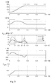
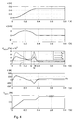
- the high acceleration of the actuator member 4 and the load 6, which underlies the speed increase, results from providing a first volume of pressurized fluid into the first working chamber 7, which can be seen from the pressure curve pa in the pressure diagram, which is plotted as an absolute pressure curve like all other pressure curves from the fact that in the second working chamber 8, whose pressure is represented by the pressure curve pb, there is only a low pressure level from the previous course of motion, so that the movement of the actuator 4 is only minimally inhibited.
- the mean pressure pm which results from the averaging of the respective pressure values from the two working chambers 7, 8, is at the beginning and end of the movement of the Aktorglieds 4 a fraction of the supply pressure applied to the valve means 9, 59, exemplarily less than 20 percent of the supply pressure according to the illustration of FIG. 4 ,
- From the associated force diagram according to the FIG. 3 can be taken from the power provided by the actuator 4 to the load 6.
- This first increases by the provision of the pressurized fluid in the first working chamber 7 to a maximum value, and then subsequently after completion of the fluid supply into the first working chamber 7 due the increasing increase in the volume of the first working chamber 7 and the thus decreasing pressure in the first working chamber 7 to fall back to zero.
- the resulting, contrary to the operation according to FIG. 3 deviating from zero holding force Fh on the actuator member 4 is the force diagram of FIG. 4 refer to.
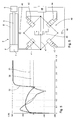
- FIG. 5 shows a force curve for a work system, which is operated in a conventional manner.
- the force curve 30 according to the FIG. 3 the force curve 31 according to FIG.
- a valve device 40 is shown, which is basically designed as an arrangement four 2/2-way valves 41, 42, 43 44.
- Each of the 2/2-way valves 41, 42, 43 44 includes a first and a second fluid port and a not shown, movable valve member for adjusting a free fluid channel cross-section between the respective first and second fluid port.
- the four 2/2-way valves 41, 42, 43, 44 are interconnected in a full bridge arrangement in which the first fluid ports of the first and second 2/2-way valve 41, 42 are connectable to a fluid source 45, the second fluid port of first 2/2-way valve 41 and the first fluid port of the fourth 2/2-way valve 44 are connected to the first working chamber 7, the second fluid port of the second 2/2-way valve 42 and the first fluid port of the third 2/2-way valve 43rd are connected to the second working chamber 8 and the second fluid ports of the third and fourth 2/2-way valve 43, 44 are connected to a vent outlet 46.
- a valve device 40 fluid flows into the working chambers 7, 8 or from the working chamber 7, 8 can be influenced in a simple manner.
- a Connecting channel 47 is formed, in which one of the control device 48 individually switchable between a blocking position and a release position, exemplarily designed as 2/2-way valve 49 valve means for influencing a free cross section of the connecting channel 47 is arranged to communicate a communication between the first working chamber 7 and the second working chamber 8 temporarily release.
Landscapes
- Engineering & Computer Science (AREA)
- Physics & Mathematics (AREA)
- Fluid Mechanics (AREA)
- Mechanical Engineering (AREA)
- General Engineering & Computer Science (AREA)
- Fluid-Pressure Circuits (AREA)
Claims (11)
- Procédé de commande d'un système de travail à actionnement fluidique (1 ; 51) qui présente un actionneur (2) avec un boîtier d'actionneur (3) et un élément actionneur (4) reçu de manière mobile dans le boîtier d'actionneur (3), le boîtier d'actionneur (3) et l'élément actionneur (4) déterminant une première et au moins une seconde chambre de travail (7, 8) qui sont mises sous pression chacune séparément et qui sont réalisées pour la mise à disposition de forces d'actionneur agissant de manière opposée l'une par rapport à l'autre sur l'élément actionneur (4), et qui présente un système de soupape (9 ; 59) qui est réalisé pour la commande séparée des deux chambres de travail (7, 8), ainsi qu'un système de commande (15 ; 65) pour la commande du système de soupape (9 ; 59), caractérisé en ce que le système de commande (15 ; 65) prescrit les étapes suivantes : la commande du système de soupape (9 ; 59) pour une mise à disposition d'un premier volume prescriptible d'un fluide mis sous pression au niveau de la première chambre de travail (7) afin d'accélérer l'élément actionneur (7) à partir d'une position de départ à une vitesse cible prescriptible, le volume prescriptible étant calculé de telle manière qu'une quantité d'énergie mise à disposition par le biais du fluide mis sous pression dans la première chambre de travail (7) suffise aussi exactement que possible pour l'accélération de l'élément actionneur (4) à la vitesse cible exigée, la commande du système de soupape (9 ; 59) afin de fermer la première chambre de travail (7), la commande du système de soupape (9 ; 59) afin de permettre un écoulement d'un second volume prescriptible d'un fluide contenu dans la seconde chambre de travail (8) hors de la seconde chambre de travail (8) de sorte qu'un freinage de l'élément actionneur (4) soit garanti à une position cible prescriptible le long du boîtier d'actionneur (3).
- Procédé selon la revendication 1, caractérisé en ce que le système de soupape (9 ; 59) est commandé pendant et/ou après le freinage de l'élément actionneur (4) de telle manière que la seconde chambre de travail (8) soit sans pression dans la position cible.
- Procédé selon la revendication 1 ou 2, caractérisé en ce que le premier volume prescriptible du fluide mis sous pression, qui est mis à disposition au niveau de la première chambre de travail (7), est calculé de telle manière qu'une pression cible prescriptible, établie en particulier sous une pression d'alimentation pour le système de soupape (9 ; 59) règne dans la première chambre de travail (7) lors de l'atteinte de la position cible.
- Procédé selon la revendication 3, caractérisé en ce que le système de soupape (9 ; 59) est commandé de telle manière qu'un troisième volume prescriptible d'un fluide mis sous pression soit amené à la première chambre de travail (7) lors de l'atteinte de la position cible afin d'augmenter la pression cible dans la première chambre de travail (7) à la fin du processus de freinage ou après l'achèvement du processus de freinage d'une quantité prescriptible.
- Procédé selon l'une quelconque des revendications 1 à 4, caractérisé en ce que le système de commande (15 ; 65) entreprend de manière temporisée la commande du système de soupape (9 ; 59) pour mettre à disposition le premier volume prescriptible au niveau de la première chambre de travail (7) et pour permettre l'écoulement d'un second volume prescriptible hors de la seconde chambre de travail (8).
- Procédé selon l'une quelconque des revendications 1 à 5, caractérisé en ce qu'un système de mesure de pression et/ou un capteur de position finale (18) et/ou un système de mesure de déplacement (71) est associé à l'actionneur et en ce qu'une commande, en particulier une régulation, du système de soupape (9 ; 59) est effectuée en fonction des valeurs de mesure qui sont mises à disposition par le système de mesure de pression et/ou l'au moins un capteur de position finale (18) et/ou le système de mesure de déplacement (71) au niveau du système de commande (15 ; 65).
- Procédé selon l'une quelconque des revendications précédentes, caractérisé en ce que la position cible pour l'élément actionneur (4) est choisie de telle manière qu'un volume de travail de la seconde chambre de travail (8) soit minimal et en ce que le premier volume pour le fluide mis sous pression et le second volume prescriptible pour le fluide s'écoulant sont prescrits de telle manière que l'élément actionneur (4) atteigne la position cible avec une vitesse de déplacement, notamment au moins presque, infime.
- Procédé selon l'une quelconque des revendications précédentes, caractérisé en ce que, pendant le déplacement entre la position de départ et la position cible, une vérification de la vitesse de l'élément actionneur (4) est entreprise par le système de commande (65) afin de permettre en cas d'écarts de la vitesse cible prescriptible une amenée supplémentaire de fluide mis sous pression dans la première chambre de travail (7) ou une limitation temporaire de l'écoulement du second volume prescriptible du fluide contenu dans la seconde chambre de travail (8) hors de la seconde chambre de travail (8).
- Procédé selon l'une quelconque des revendications précédentes, caractérisé en ce que l'écoulement du second volume prescriptible du fluide contenu dans la seconde chambre de travail (8) hors de la seconde chambre de travail (8) est effectué sans étranglement.
- Procédé selon l'une quelconque des revendications précédentes, caractérisé en ce que le système de commande (15; 65) commande le système de soupape (9 ; 59) pour une mise à disposition d'un premier volume prescriptible d'un fluide mis sous pression au niveau de la première chambre de travail (7) et pour un écoulement d'un second volume prescriptible d'un fluide contenu dans la seconde chambre de travail (8) hors de la seconde chambre de travail (8) de telle manière qu'une pression moyenne des valeurs de pression des deux chambres de travail (7, 8) se trouve au début et à la fin d'un mouvement de l'élément actionneur (4) à un niveau de pression qui s'élève à moins de 30 pour cent, de préférence à moins de 20 pour cent, en particulier à moins de 10 pour cent, d'une pression d'alimentation régnant sur le système de soupape.
- Procédé selon la revendication 10, caractérisé en ce que la pression moyenne augmente par l'amenée d'un premier volume de fluide mis sous pression dans la première chambre de travail (7) à une première valeur maximale et adopte au moment de la libération du fluide comprimé dans la seconde chambre de travail (8) par le mouvement de l'élément actionneur (4) une seconde valeur maximale et atteint temporairement un niveau de pression entre la première et la seconde valeur maximale qui s'élève à moins de 30 pour cent, de préférence à moins de 20 pour cent, en particulier à moins de 10 pour cent, d'une pression d'alimentation régnant sur le système de soupape.
Priority Applications (2)
| Application Number | Priority Date | Filing Date | Title |
|---|---|---|---|
| EP20120002099 EP2644904B1 (fr) | 2012-03-26 | 2012-03-26 | Procédé de commande d'un système de travail à actionnement fluidique |
| CN201310098292.2A CN103362901B (zh) | 2012-03-26 | 2013-03-26 | 用于操控可流体运行的工作系统的方法以及工作系统 |
Applications Claiming Priority (1)
| Application Number | Priority Date | Filing Date | Title |
|---|---|---|---|
| EP20120002099 EP2644904B1 (fr) | 2012-03-26 | 2012-03-26 | Procédé de commande d'un système de travail à actionnement fluidique |
Publications (2)
| Publication Number | Publication Date |
|---|---|
| EP2644904A1 EP2644904A1 (fr) | 2013-10-02 |
| EP2644904B1 true EP2644904B1 (fr) | 2014-11-12 |
Family
ID=45936653
Family Applications (1)
| Application Number | Title | Priority Date | Filing Date |
|---|---|---|---|
| EP20120002099 Active EP2644904B1 (fr) | 2012-03-26 | 2012-03-26 | Procédé de commande d'un système de travail à actionnement fluidique |
Country Status (2)
| Country | Link |
|---|---|
| EP (1) | EP2644904B1 (fr) |
| CN (1) | CN103362901B (fr) |
Cited By (4)
| Publication number | Priority date | Publication date | Assignee | Title |
|---|---|---|---|---|
| DE102018118955A1 (de) * | 2018-08-03 | 2020-02-06 | Schunk Gmbh & Co. Kg Spann- Und Greiftechnik | Verfahren zum Betreiben einer fluidischen Vorrichtung zum Handhaben, Bewegen oder Spannen von Gegenständen zur Bestimmung von Leckagen am Kolben und derartige Vorrichtung |
| EP3658782B1 (fr) * | 2017-07-27 | 2024-10-09 | SCHUNK SE & Co. KG Spanntechnik Greiftechnik Automatisierungstechnik | Unité de pivotement |
| DE102024111038A1 (de) | 2024-04-19 | 2025-10-23 | Festo Se & Co. Kg | Pneumatisches System zur Positionsregelung und Verfahren |
| EP4692565A1 (fr) | 2024-08-06 | 2026-02-11 | Festo SE & Co. KG | Système de soupapes et procédé de commande d'un actionneur pneumatique |
Families Citing this family (11)
| Publication number | Priority date | Publication date | Assignee | Title |
|---|---|---|---|---|
| DE102013020309B4 (de) | 2013-12-03 | 2026-03-19 | Festo Se & Co. Kg | Ventileinrichtung |
| DE102016204538B3 (de) * | 2016-03-18 | 2017-08-24 | Festo Ag & Co. Kg | Antriebseinrichtung und Verfahren zum Betreiben einer Antriebseinrichtung |
| IT201600084066A1 (it) * | 2016-08-09 | 2018-02-09 | Safen Fluid And Mech Engineering S R L | Procedimento per l'alimentazione di un'utenza pneumatica |
| DE102017009374B4 (de) * | 2017-10-10 | 2019-08-22 | Aventics Gmbh | Ventilanordnung und Steuerungsverfahren |
| JP6467733B1 (ja) * | 2018-05-21 | 2019-02-13 | Smc株式会社 | 流体圧シリンダの駆動方法及び駆動装置 |
| DE102018217337A1 (de) * | 2018-10-10 | 2020-04-16 | Festo Se & Co. Kg | Bewegungsvorrichtung, Reifenhandhabungsvorrichtung und Verfahren zum Betrieb eines fluidischen Aktors |
| CN109555749B (zh) * | 2019-01-03 | 2023-09-12 | 杨斌堂 | 多管自给装置 |
| DE102019204167B4 (de) * | 2019-03-26 | 2021-10-21 | Festo Se & Co. Kg | Assistenzvorrichtung und Verfahren zum Betreiben einer Assistenzvorrichtung |
| DE102019120863A1 (de) * | 2019-08-01 | 2021-02-04 | Atlas Copco Ias Gmbh | Verfahren zur Steuerung eines mechanischen Füge- oder Umformprozesses |
| DE102020205446B4 (de) * | 2020-04-29 | 2022-02-10 | Festo Se & Co. Kg | Arbeitseinrichtung zur Durchführung eines Arbeitsvorgangs und Verfahren zum Betreiben einer Arbeitseinrichtung |
| US12298171B2 (en) * | 2020-04-30 | 2025-05-13 | Fisher Controls International Llc | Methods and apparatus for quantifying pneumatic volume usage via valve controllers |
Family Cites Families (7)
| Publication number | Priority date | Publication date | Assignee | Title |
|---|---|---|---|---|
| US5218895A (en) * | 1990-06-15 | 1993-06-15 | Caterpillar Inc. | Electrohydraulic control apparatus and method |
| AU767094B2 (en) * | 1999-10-27 | 2003-10-30 | Tol-O-Matic Inc. | Precision servo control system for a pneumatic actuator |
| AT501935A1 (de) * | 2005-05-20 | 2006-12-15 | Sticht Fertigungstech Stiwa | Fluidisch betätigter antrieb sowie verfahren zur steuerung desselben |
| DE102008007651B3 (de) | 2008-02-06 | 2009-09-24 | Samson Aktiengesellschaft | Stellungsregler für doppeltwirkenden, pneumatischen Stellantrieb, doppeltwirkender, pneumatischer Stellantrieb und Verfahren zum Betreiben des doppeltwirkenden, pneumatischen Stellantriebs |
| CN100575716C (zh) * | 2008-03-21 | 2009-12-30 | 太原理工大学 | 一种冗余电液伺服控制系统 |
| CN101344102B (zh) * | 2008-08-27 | 2010-06-23 | 华南理工大学 | 含有柱塞式双出杆气液缸的气液联控位置和速度伺服控制装置 |
| DE102009017879A1 (de) | 2009-04-17 | 2010-10-21 | Festo Ag & Co. Kg | Fluidtechnisches System |
-
2012
- 2012-03-26 EP EP20120002099 patent/EP2644904B1/fr active Active
-
2013
- 2013-03-26 CN CN201310098292.2A patent/CN103362901B/zh active Active
Cited By (6)
| Publication number | Priority date | Publication date | Assignee | Title |
|---|---|---|---|---|
| EP3658782B1 (fr) * | 2017-07-27 | 2024-10-09 | SCHUNK SE & Co. KG Spanntechnik Greiftechnik Automatisierungstechnik | Unité de pivotement |
| DE102018118955A1 (de) * | 2018-08-03 | 2020-02-06 | Schunk Gmbh & Co. Kg Spann- Und Greiftechnik | Verfahren zum Betreiben einer fluidischen Vorrichtung zum Handhaben, Bewegen oder Spannen von Gegenständen zur Bestimmung von Leckagen am Kolben und derartige Vorrichtung |
| DE102018118955B4 (de) * | 2018-08-03 | 2020-02-13 | Schunk Gmbh & Co. Kg Spann- Und Greiftechnik | Verfahren zum Betreiben einer fluidischen Vorrichtung zum Handhaben, Bewegen oder Spannen von Gegenständen zur Bestimmung von Leckagen am Kolben und derartige Vorrichtung |
| DE102024111038A1 (de) | 2024-04-19 | 2025-10-23 | Festo Se & Co. Kg | Pneumatisches System zur Positionsregelung und Verfahren |
| DE102024111038B4 (de) | 2024-04-19 | 2025-11-06 | Festo Se & Co. Kg | Pneumatisches System zur Positionsregelung und Verfahren |
| EP4692565A1 (fr) | 2024-08-06 | 2026-02-11 | Festo SE & Co. KG | Système de soupapes et procédé de commande d'un actionneur pneumatique |
Also Published As
| Publication number | Publication date |
|---|---|
| CN103362901B (zh) | 2016-04-06 |
| EP2644904A1 (fr) | 2013-10-02 |
| CN103362901A (zh) | 2013-10-23 |
Similar Documents
| Publication | Publication Date | Title |
|---|---|---|
| EP2644904A1 (fr) | Procédé de commande d'un système de travail à actionnement fluidique et système de travail | |
| EP1067319B1 (fr) | Dispositif de commande pour actionneur de transmission | |
| EP3445977B1 (fr) | Procédé d'alimentation en air comprimé d'un consommateur d'air comprimé | |
| DE10344480B3 (de) | Hydraulische Ventilanordnung | |
| DE112014006747B4 (de) | Verfahren zur Bewegungsregelung eines Aktors | |
| EP2419646B1 (fr) | Système technique fluidique | |
| EP1664551A1 (fr) | Dispositif de commande et procede d'alimentation en milieu sous pression d'au moins deux charges hydrauliques | |
| DE102012016838B4 (de) | Hydraulische Steuerschaltung für eine hydraulisch betätigte Gießeinheit | |
| DE10122297C1 (de) | Vorrichtung zur gedämpften Positionierung eines in einem Zylinder verschiebbaren Kolbens in einer Anschlagposition | |
| DE102010032750B4 (de) | Pneumatikantrieb | |
| EP2435713A1 (fr) | Procédé destiné à enlever des impuretés d'un régulateur numérique de pression hydraulique d'un système hydraulique | |
| WO2017016867A1 (fr) | Amortisseur de vibrations pour un véhicule automobile | |
| EP2294331A1 (fr) | Dispositif de vanne hydraulique | |
| EP3592143A1 (fr) | Système de commande et/ou de régulation d'un véhicule utilitaire agricole et procédé de commande et/ou de régulation d'un véhicule utilitaire agricole | |
| DE102016106589A1 (de) | Elektrohydraulischer Steuerkreis mit Schrittmotor | |
| WO2017005245A1 (fr) | Unité de machine hydraulique et procédé de fonctionnement d'une telle unité de machine | |
| EP2535624A1 (fr) | Clapet de limitation de pression | |
| DE102012210799A1 (de) | Hydraulische Steuervorrichtung mit Volumenstromsensor für jedes Stellglied | |
| WO2012126662A1 (fr) | Procédé de commande d'un système de commutation automatique ou automatisé | |
| DE10138026C2 (de) | Pneumatikantriebssteuerung zum Steuern des Bewegungsablaufs von Pneumatikantrieben | |
| DE102019131201A1 (de) | Semiaktiver elektrohydraulischer Aktuator | |
| EP1624168A2 (fr) | Vérin pneumatique et méthode pour contrôler en continu la position d'un cylindre pneumatique | |
| EP4211355B1 (fr) | Système d'entraînement alimenté par gaz et procédé de fonctionnement | |
| DE102008024338B4 (de) | Elektro-pneumatisches Antriebssystem sowie Verfahren zu seinem Betreiben | |
| DE1263432B (de) | Druckmittelbetaetigtes Ventil insbesondere fuer Gasturbinenanlagen |
Legal Events
| Date | Code | Title | Description |
|---|---|---|---|
| PUAI | Public reference made under article 153(3) epc to a published international application that has entered the european phase |
Free format text: ORIGINAL CODE: 0009012 |
|
| AK | Designated contracting states |
Kind code of ref document: A1 Designated state(s): AL AT BE BG CH CY CZ DE DK EE ES FI FR GB GR HR HU IE IS IT LI LT LU LV MC MK MT NL NO PL PT RO RS SE SI SK SM TR |
|
| AX | Request for extension of the european patent |
Extension state: BA ME |
|
| 17P | Request for examination filed |
Effective date: 20140331 |
|
| RBV | Designated contracting states (corrected) |
Designated state(s): AL AT BE BG CH CY CZ DE DK EE ES FI FR GB GR HR HU IE IS IT LI LT LU LV MC MK MT NL NO PL PT RO RS SE SI SK SM TR |
|
| GRAP | Despatch of communication of intention to grant a patent |
Free format text: ORIGINAL CODE: EPIDOSNIGR1 |
|
| INTG | Intention to grant announced |
Effective date: 20140605 |
|
| GRAS | Grant fee paid |
Free format text: ORIGINAL CODE: EPIDOSNIGR3 |
|
| GRAA | (expected) grant |
Free format text: ORIGINAL CODE: 0009210 |
|
| AK | Designated contracting states |
Kind code of ref document: B1 Designated state(s): AL AT BE BG CH CY CZ DE DK EE ES FI FR GB GR HR HU IE IS IT LI LT LU LV MC MK MT NL NO PL PT RO RS SE SI SK SM TR |
|
| REG | Reference to a national code |
Ref country code: GB Ref legal event code: FG4D Free format text: NOT ENGLISH |
|
| REG | Reference to a national code |
Ref country code: CH Ref legal event code: EP |
|
| REG | Reference to a national code |
Ref country code: AT Ref legal event code: REF Ref document number: 695955 Country of ref document: AT Kind code of ref document: T Effective date: 20141115 |
|
| REG | Reference to a national code |
Ref country code: IE Ref legal event code: FG4D Free format text: LANGUAGE OF EP DOCUMENT: GERMAN |
|
| REG | Reference to a national code |
Ref country code: DE Ref legal event code: R096 Ref document number: 502012001551 Country of ref document: DE Effective date: 20141224 |
|
| REG | Reference to a national code |
Ref country code: NL Ref legal event code: VDEP Effective date: 20141112 |
|
| PG25 | Lapsed in a contracting state [announced via postgrant information from national office to epo] |
Ref country code: PT Free format text: LAPSE BECAUSE OF FAILURE TO SUBMIT A TRANSLATION OF THE DESCRIPTION OR TO PAY THE FEE WITHIN THE PRESCRIBED TIME-LIMIT Effective date: 20150312 Ref country code: NL Free format text: LAPSE BECAUSE OF FAILURE TO SUBMIT A TRANSLATION OF THE DESCRIPTION OR TO PAY THE FEE WITHIN THE PRESCRIBED TIME-LIMIT Effective date: 20141112 Ref country code: IS Free format text: LAPSE BECAUSE OF FAILURE TO SUBMIT A TRANSLATION OF THE DESCRIPTION OR TO PAY THE FEE WITHIN THE PRESCRIBED TIME-LIMIT Effective date: 20150312 Ref country code: ES Free format text: LAPSE BECAUSE OF FAILURE TO SUBMIT A TRANSLATION OF THE DESCRIPTION OR TO PAY THE FEE WITHIN THE PRESCRIBED TIME-LIMIT Effective date: 20141112 Ref country code: LT Free format text: LAPSE BECAUSE OF FAILURE TO SUBMIT A TRANSLATION OF THE DESCRIPTION OR TO PAY THE FEE WITHIN THE PRESCRIBED TIME-LIMIT Effective date: 20141112 Ref country code: NO Free format text: LAPSE BECAUSE OF FAILURE TO SUBMIT A TRANSLATION OF THE DESCRIPTION OR TO PAY THE FEE WITHIN THE PRESCRIBED TIME-LIMIT Effective date: 20150212 Ref country code: FI Free format text: LAPSE BECAUSE OF FAILURE TO SUBMIT A TRANSLATION OF THE DESCRIPTION OR TO PAY THE FEE WITHIN THE PRESCRIBED TIME-LIMIT Effective date: 20141112 |
|
| PG25 | Lapsed in a contracting state [announced via postgrant information from national office to epo] |
Ref country code: LV Free format text: LAPSE BECAUSE OF FAILURE TO SUBMIT A TRANSLATION OF THE DESCRIPTION OR TO PAY THE FEE WITHIN THE PRESCRIBED TIME-LIMIT Effective date: 20141112 Ref country code: HR Free format text: LAPSE BECAUSE OF FAILURE TO SUBMIT A TRANSLATION OF THE DESCRIPTION OR TO PAY THE FEE WITHIN THE PRESCRIBED TIME-LIMIT Effective date: 20141112 Ref country code: RS Free format text: LAPSE BECAUSE OF FAILURE TO SUBMIT A TRANSLATION OF THE DESCRIPTION OR TO PAY THE FEE WITHIN THE PRESCRIBED TIME-LIMIT Effective date: 20141112 Ref country code: SE Free format text: LAPSE BECAUSE OF FAILURE TO SUBMIT A TRANSLATION OF THE DESCRIPTION OR TO PAY THE FEE WITHIN THE PRESCRIBED TIME-LIMIT Effective date: 20141112 Ref country code: PL Free format text: LAPSE BECAUSE OF FAILURE TO SUBMIT A TRANSLATION OF THE DESCRIPTION OR TO PAY THE FEE WITHIN THE PRESCRIBED TIME-LIMIT Effective date: 20141112 Ref country code: CY Free format text: LAPSE BECAUSE OF FAILURE TO SUBMIT A TRANSLATION OF THE DESCRIPTION OR TO PAY THE FEE WITHIN THE PRESCRIBED TIME-LIMIT Effective date: 20141112 Ref country code: GR Free format text: LAPSE BECAUSE OF FAILURE TO SUBMIT A TRANSLATION OF THE DESCRIPTION OR TO PAY THE FEE WITHIN THE PRESCRIBED TIME-LIMIT Effective date: 20150213 |
|
| PG25 | Lapsed in a contracting state [announced via postgrant information from national office to epo] |
Ref country code: CZ Free format text: LAPSE BECAUSE OF FAILURE TO SUBMIT A TRANSLATION OF THE DESCRIPTION OR TO PAY THE FEE WITHIN THE PRESCRIBED TIME-LIMIT Effective date: 20141112 Ref country code: RO Free format text: LAPSE BECAUSE OF FAILURE TO SUBMIT A TRANSLATION OF THE DESCRIPTION OR TO PAY THE FEE WITHIN THE PRESCRIBED TIME-LIMIT Effective date: 20141112 Ref country code: DK Free format text: LAPSE BECAUSE OF FAILURE TO SUBMIT A TRANSLATION OF THE DESCRIPTION OR TO PAY THE FEE WITHIN THE PRESCRIBED TIME-LIMIT Effective date: 20141112 Ref country code: EE Free format text: LAPSE BECAUSE OF FAILURE TO SUBMIT A TRANSLATION OF THE DESCRIPTION OR TO PAY THE FEE WITHIN THE PRESCRIBED TIME-LIMIT Effective date: 20141112 Ref country code: SK Free format text: LAPSE BECAUSE OF FAILURE TO SUBMIT A TRANSLATION OF THE DESCRIPTION OR TO PAY THE FEE WITHIN THE PRESCRIBED TIME-LIMIT Effective date: 20141112 |
|
| REG | Reference to a national code |
Ref country code: DE Ref legal event code: R097 Ref document number: 502012001551 Country of ref document: DE |
|
| PLBE | No opposition filed within time limit |
Free format text: ORIGINAL CODE: 0009261 |
|
| STAA | Information on the status of an ep patent application or granted ep patent |
Free format text: STATUS: NO OPPOSITION FILED WITHIN TIME LIMIT |
|
| 26N | No opposition filed |
Effective date: 20150813 |
|
| PG25 | Lapsed in a contracting state [announced via postgrant information from national office to epo] |
Ref country code: LU Free format text: LAPSE BECAUSE OF FAILURE TO SUBMIT A TRANSLATION OF THE DESCRIPTION OR TO PAY THE FEE WITHIN THE PRESCRIBED TIME-LIMIT Effective date: 20150326 Ref country code: MC Free format text: LAPSE BECAUSE OF FAILURE TO SUBMIT A TRANSLATION OF THE DESCRIPTION OR TO PAY THE FEE WITHIN THE PRESCRIBED TIME-LIMIT Effective date: 20141112 |
|
| REG | Reference to a national code |
Ref country code: CH Ref legal event code: PL |
|
| REG | Reference to a national code |
Ref country code: IE Ref legal event code: MM4A |
|
| PG25 | Lapsed in a contracting state [announced via postgrant information from national office to epo] |
Ref country code: LI Free format text: LAPSE BECAUSE OF NON-PAYMENT OF DUE FEES Effective date: 20150331 Ref country code: IE Free format text: LAPSE BECAUSE OF NON-PAYMENT OF DUE FEES Effective date: 20150326 Ref country code: CH Free format text: LAPSE BECAUSE OF NON-PAYMENT OF DUE FEES Effective date: 20150331 |
|
| PG25 | Lapsed in a contracting state [announced via postgrant information from national office to epo] |
Ref country code: SI Free format text: LAPSE BECAUSE OF FAILURE TO SUBMIT A TRANSLATION OF THE DESCRIPTION OR TO PAY THE FEE WITHIN THE PRESCRIBED TIME-LIMIT Effective date: 20141112 |
|
| REG | Reference to a national code |
Ref country code: FR Ref legal event code: PLFP Year of fee payment: 5 |
|
| PG25 | Lapsed in a contracting state [announced via postgrant information from national office to epo] |
Ref country code: MT Free format text: LAPSE BECAUSE OF FAILURE TO SUBMIT A TRANSLATION OF THE DESCRIPTION OR TO PAY THE FEE WITHIN THE PRESCRIBED TIME-LIMIT Effective date: 20141112 |
|
| REG | Reference to a national code |
Ref country code: FR Ref legal event code: PLFP Year of fee payment: 6 |
|
| PG25 | Lapsed in a contracting state [announced via postgrant information from national office to epo] |
Ref country code: BG Free format text: LAPSE BECAUSE OF FAILURE TO SUBMIT A TRANSLATION OF THE DESCRIPTION OR TO PAY THE FEE WITHIN THE PRESCRIBED TIME-LIMIT Effective date: 20141112 Ref country code: SM Free format text: LAPSE BECAUSE OF FAILURE TO SUBMIT A TRANSLATION OF THE DESCRIPTION OR TO PAY THE FEE WITHIN THE PRESCRIBED TIME-LIMIT Effective date: 20141112 Ref country code: HU Free format text: LAPSE BECAUSE OF FAILURE TO SUBMIT A TRANSLATION OF THE DESCRIPTION OR TO PAY THE FEE WITHIN THE PRESCRIBED TIME-LIMIT; INVALID AB INITIO Effective date: 20120326 |
|
| PG25 | Lapsed in a contracting state [announced via postgrant information from national office to epo] |
Ref country code: BE Free format text: LAPSE BECAUSE OF NON-PAYMENT OF DUE FEES Effective date: 20150331 |
|
| PG25 | Lapsed in a contracting state [announced via postgrant information from national office to epo] |
Ref country code: TR Free format text: LAPSE BECAUSE OF FAILURE TO SUBMIT A TRANSLATION OF THE DESCRIPTION OR TO PAY THE FEE WITHIN THE PRESCRIBED TIME-LIMIT Effective date: 20141112 |
|
| REG | Reference to a national code |
Ref country code: FR Ref legal event code: PLFP Year of fee payment: 7 |
|
| PGFP | Annual fee paid to national office [announced via postgrant information from national office to epo] |
Ref country code: GB Payment date: 20180219 Year of fee payment: 7 |
|
| REG | Reference to a national code |
Ref country code: AT Ref legal event code: MM01 Ref document number: 695955 Country of ref document: AT Kind code of ref document: T Effective date: 20170326 |
|
| PGFP | Annual fee paid to national office [announced via postgrant information from national office to epo] |
Ref country code: IT Payment date: 20180322 Year of fee payment: 7 Ref country code: FR Payment date: 20180326 Year of fee payment: 7 |
|
| PG25 | Lapsed in a contracting state [announced via postgrant information from national office to epo] |
Ref country code: MK Free format text: LAPSE BECAUSE OF FAILURE TO SUBMIT A TRANSLATION OF THE DESCRIPTION OR TO PAY THE FEE WITHIN THE PRESCRIBED TIME-LIMIT Effective date: 20141112 |
|
| PG25 | Lapsed in a contracting state [announced via postgrant information from national office to epo] |
Ref country code: AT Free format text: LAPSE BECAUSE OF NON-PAYMENT OF DUE FEES Effective date: 20170326 |
|
| PG25 | Lapsed in a contracting state [announced via postgrant information from national office to epo] |
Ref country code: AL Free format text: LAPSE BECAUSE OF FAILURE TO SUBMIT A TRANSLATION OF THE DESCRIPTION OR TO PAY THE FEE WITHIN THE PRESCRIBED TIME-LIMIT Effective date: 20141112 |
|
| GBPC | Gb: european patent ceased through non-payment of renewal fee |
Effective date: 20190326 |
|
| PG25 | Lapsed in a contracting state [announced via postgrant information from national office to epo] |
Ref country code: GB Free format text: LAPSE BECAUSE OF NON-PAYMENT OF DUE FEES Effective date: 20190326 |
|
| REG | Reference to a national code |
Ref country code: DE Ref legal event code: R082 Ref document number: 502012001551 Country of ref document: DE Representative=s name: PATENTANWAELTE MAGENBAUER & KOLLEGEN PARTNERSC, DE Ref country code: DE Ref legal event code: R081 Ref document number: 502012001551 Country of ref document: DE Owner name: FESTO SE & CO. KG, DE Free format text: FORMER OWNER: FESTO AG & CO. KG, 73734 ESSLINGEN, DE Ref country code: DE Ref legal event code: R081 Ref document number: 502012001551 Country of ref document: DE Owner name: FESTO AG & CO. KG, DE Free format text: FORMER OWNER: FESTO AG & CO. KG, 73734 ESSLINGEN, DE |
|
| PG25 | Lapsed in a contracting state [announced via postgrant information from national office to epo] |
Ref country code: IT Free format text: LAPSE BECAUSE OF NON-PAYMENT OF DUE FEES Effective date: 20190326 Ref country code: FR Free format text: LAPSE BECAUSE OF NON-PAYMENT OF DUE FEES Effective date: 20190331 |
|
| P01 | Opt-out of the competence of the unified patent court (upc) registered |
Effective date: 20230623 |
|
| PGFP | Annual fee paid to national office [announced via postgrant information from national office to epo] |
Ref country code: DE Payment date: 20260325 Year of fee payment: 15 |