EP2644936A2 - Poulie à courroie découplée - Google Patents
Poulie à courroie découplée Download PDFInfo
- Publication number
- EP2644936A2 EP2644936A2 EP13000488.0A EP13000488A EP2644936A2 EP 2644936 A2 EP2644936 A2 EP 2644936A2 EP 13000488 A EP13000488 A EP 13000488A EP 2644936 A2 EP2644936 A2 EP 2644936A2
- Authority
- EP
- European Patent Office
- Prior art keywords
- pulley
- pulley according
- radial
- spring
- projection
- Prior art date
- Legal status (The legal status is an assumption and is not a legal conclusion. Google has not performed a legal analysis and makes no representation as to the accuracy of the status listed.)
- Withdrawn
Links
Images
Classifications
-
- F—MECHANICAL ENGINEERING; LIGHTING; HEATING; WEAPONS; BLASTING
- F16—ENGINEERING ELEMENTS AND UNITS; GENERAL MEASURES FOR PRODUCING AND MAINTAINING EFFECTIVE FUNCTIONING OF MACHINES OR INSTALLATIONS; THERMAL INSULATION IN GENERAL
- F16F—SPRINGS; SHOCK-ABSORBERS; MEANS FOR DAMPING VIBRATION
- F16F15/00—Suppression of vibrations in systems; Means or arrangements for avoiding or reducing out-of-balance forces, e.g. due to motion
- F16F15/10—Suppression of vibrations in rotating systems by making use of members moving with the system
- F16F15/12—Suppression of vibrations in rotating systems by making use of members moving with the system using elastic members or friction-damping members, e.g. between a rotating shaft and a gyratory mass mounted thereon
- F16F15/121—Suppression of vibrations in rotating systems by making use of members moving with the system using elastic members or friction-damping members, e.g. between a rotating shaft and a gyratory mass mounted thereon using springs as elastic members, e.g. metallic springs
- F16F15/124—Elastomeric springs
- F16F15/126—Elastomeric springs consisting of at least one annular element surrounding the axis of rotation
-
- F—MECHANICAL ENGINEERING; LIGHTING; HEATING; WEAPONS; BLASTING
- F16—ENGINEERING ELEMENTS AND UNITS; GENERAL MEASURES FOR PRODUCING AND MAINTAINING EFFECTIVE FUNCTIONING OF MACHINES OR INSTALLATIONS; THERMAL INSULATION IN GENERAL
- F16D—COUPLINGS FOR TRANSMITTING ROTATION; CLUTCHES; BRAKES
- F16D3/00—Yielding couplings, i.e. with means permitting movement between the connected parts during the drive
- F16D3/50—Yielding couplings, i.e. with means permitting movement between the connected parts during the drive with the coupling parts connected by one or more intermediate members
- F16D3/76—Yielding couplings, i.e. with means permitting movement between the connected parts during the drive with the coupling parts connected by one or more intermediate members shaped as an elastic ring centered on the axis, surrounding a portion of one coupling part and surrounded by a sleeve of the other coupling part
-
- F—MECHANICAL ENGINEERING; LIGHTING; HEATING; WEAPONS; BLASTING
- F16—ENGINEERING ELEMENTS AND UNITS; GENERAL MEASURES FOR PRODUCING AND MAINTAINING EFFECTIVE FUNCTIONING OF MACHINES OR INSTALLATIONS; THERMAL INSULATION IN GENERAL
- F16D—COUPLINGS FOR TRANSMITTING ROTATION; CLUTCHES; BRAKES
- F16D41/00—Freewheels or freewheel clutches
- F16D41/20—Freewheels or freewheel clutches with expandable or contractable clamping ring or band
- F16D41/206—Freewheels or freewheel clutches with expandable or contractable clamping ring or band having axially adjacent coils, e.g. helical wrap-springs
-
- F—MECHANICAL ENGINEERING; LIGHTING; HEATING; WEAPONS; BLASTING
- F16—ENGINEERING ELEMENTS AND UNITS; GENERAL MEASURES FOR PRODUCING AND MAINTAINING EFFECTIVE FUNCTIONING OF MACHINES OR INSTALLATIONS; THERMAL INSULATION IN GENERAL
- F16D—COUPLINGS FOR TRANSMITTING ROTATION; CLUTCHES; BRAKES
- F16D47/00—Systems of clutches, or clutches and couplings, comprising devices of types grouped under at least two of the following sets of groups: F16D1/00 - F16D9/00, F16D11/00 - F16D23/00, F16D25/00 - F16D29/00, F16D31/00 - F16D39/00, F16D41/00 - F16D45/00
- F16D47/02—Systems of clutches, or clutches and couplings, comprising devices of types grouped under at least two of the following sets of groups: F16D1/00 - F16D9/00, F16D11/00 - F16D23/00, F16D25/00 - F16D29/00, F16D31/00 - F16D39/00, F16D41/00 - F16D45/00 of which at least one is a coupling
-
- F—MECHANICAL ENGINEERING; LIGHTING; HEATING; WEAPONS; BLASTING
- F16—ENGINEERING ELEMENTS AND UNITS; GENERAL MEASURES FOR PRODUCING AND MAINTAINING EFFECTIVE FUNCTIONING OF MACHINES OR INSTALLATIONS; THERMAL INSULATION IN GENERAL
- F16H—GEARING
- F16H55/00—Elements with teeth or friction surfaces for conveying motion; Worms, pulleys or sheaves for gearing mechanisms
- F16H55/32—Friction members
- F16H55/36—Pulleys
-
- F—MECHANICAL ENGINEERING; LIGHTING; HEATING; WEAPONS; BLASTING
- F16—ENGINEERING ELEMENTS AND UNITS; GENERAL MEASURES FOR PRODUCING AND MAINTAINING EFFECTIVE FUNCTIONING OF MACHINES OR INSTALLATIONS; THERMAL INSULATION IN GENERAL
- F16H—GEARING
- F16H55/00—Elements with teeth or friction surfaces for conveying motion; Worms, pulleys or sheaves for gearing mechanisms
- F16H55/32—Friction members
- F16H55/36—Pulleys
- F16H2055/366—Pulleys with means providing resilience or vibration damping
Definitions
- the invention relates to a decoupled pulley, comprising a drive and an output, wherein between the drive and the output, a decoupling device for decoupling of torsional vibrations is arranged, wherein the decoupling device in the direction of the torque curve initially comprises a spring element and then an overrunning clutch, which in a functional Series connection are arranged.
- Such a decoupled pulley is from the DE 10 2009 014203 A1 known.
- the previously known decoupled pulley is used in a drive train, in particular in an internal combustion engine and an auxiliary unit connecting traction drive for use.
- the order of arrangement of the spring element and the one-way clutch in a functional series connection can be freely designed, for example, the one-way clutch can be arranged in the direction of the torque curve in front of the spring element.
- the overrunning clutch of the prior art decoupled pulley can be designed differently, for. B. by a wrap.
- the introduction of the torque via the pulley body, the spring element and the overrunning clutch to the output takes place, wherein the output is connected to the input shaft of an auxiliary unit, for example an air conditioning compressor.
- the previously known decoupled pulley can be mounted directly on the auxiliary unit and fixed there.
- the invention has for its object to further develop a decoupled pulley of the known type such that drive and output can also be different.
- the drive is formed by a hub ring which is rotatably mounted on a crankshaft of an internal combustion engine and the output by a pulley body through which an accessory of the internal combustion engine is driven.
- the decoupled pulley can be mounted directly on the crankshaft and fixed there against rotation.
- the output on the accessory is then carried out by a belt which is mounted on the outer circumference of the pulley body.
- hybrid drives for example, an internal combustion engine with an additional electric motor.
- the hybrid drive additionally generates vibrations in the belt drive, which are effectively reduced, ideally suppressed.
- the decoupling device for decoupling rotational vibrations between a drive and an output is arranged, wherein the decoupling device in the direction of the torque curve comprises first a spring element and then an overrunning clutch, which are arranged in a functional series connection
- the decoupling device in the direction of the torque curve comprises first a spring element and then an overrunning clutch, which are arranged in a functional series connection
- the overrunning clutch is formed by a wrap spring freewheel. If necessary, the wrap spring freewheel can also be designed with a shift gate.
- the freewheel function with wrap springs is characterized by the fact that the release torque and thus the number of switching operations can be controlled. If the release torque is smaller, increases the number of switching operations, the release torque is greater, the number of switching operations is reduced. As a result, the life and function of the torque-controlled circuit can be improved and adapted to the corresponding required switching point. The fact that the freewheel only switches when the decoupling is actually necessary, the number of shifts can be reduced, so that the decoupled pulley has consistently good performance characteristics during a long service life.
- the switching process of the wrap spring freewheel can take place at a certain variable time.
- wrap-around freewheels In contrast to conventional freewheels, which are complicated to manufacture and expensive, z. B. in that mating surfaces must be tightly tolerated and hardened, the use of a wrap spring free running is simpler, cheaper and equally effective for use in a decoupled pulley. In addition, wrap-around freewheels have the advantage that they, in contrast to conventional freewheels with sprags harmoniously engage.
- the wrap spring freewheel can surround the spring element with a radial spacing, wherein an inner support sleeve is arranged in the gap formed by the gap.
- the inner support sleeve forms together with the spring element preferably a vulcanized rubber-metal part, wherein the spring element radially inwardly z. B. may be formed according to the hub ring.
- the inner support sleeve forms one of the running surfaces for the wrap spring freewheel.
- the spring element may consist of an elastomeric material. Such materials for spring elements are well known in different specifications, including for use in decoupled pulleys.
- a preferably cohesive connection between the spring element and the inner support sleeve causes a simple low-part and therefore inexpensive construction of the decoupled pulley.
- the pulley body may be C-shaped open in the axial direction, with a radially inner and a radially outer axial projection, which are frontally connected on the one hand by a radial projection.
- Such a configuration of a pulley body is advantageous if the dimensions of the installation space in which the pulley is to be used is limited in the axial direction. Due to the C-shaped shape of the pulley body, it is possible within the gap between the radially inner and the radially outer axial projection z. B. to arrange the guide flange of a flywheel, as will be explained later. The pulley thereby builds compact in the axial direction.
- the wrap spring freewheel can be axially sealed on both sides by a respective sealing ring, wherein the sealing rings are arranged radially between the inner support sleeve and the inner axial projection.
- Wrap-around freewheels must be greased on the one hand in order to function properly. On the other hand, it must be ensured that the grease for lubrication of the wrap spring freewheel during the intended use of the pulley reliably held in the installation space of the wrap spring freewheel is, and in no case in the environment, in particular not on the pulley body and guided over the pulley body belt passes.
- the sealing rings may preferably be formed as radial shaft seals.
- the inner support sleeve may on the one hand have a radially outwardly extending support collar, which contacts the radial projection adjacent.
- the support collar thereby forms an axial stop for the pulley body.
- the pulley body is, based on the inner support sleeve, thereby guided in the radial and axial directions. Unwanted wobbling is excluded.
- the radial projection may contact the support collar by means of an axial sliding bearing.
- Sliding bearing build compared to rolling bearings, usually much smaller, so that the pulley according to the invention has a total of compact dimension in both the radial and in the axial direction.
- a guide flange may be arranged, which is connected by means of a spring body with a flywheel.
- various elements for vibration isolation and vibration damping can be used, individually or in combination with each other.
- the spring body consists of an elastomeric material.
- the guide flange, the spring body and the flywheel ring may preferably be formed as a rubber-metal part, wherein the spring body by vulcanization preferably with the guide flange and the flywheel connected is.
- the guide flange, the spring body and the flywheel ring form a preassembled unit.
- the guide flange can be supported by means of a bearing in the radial and / or axial direction on one of the axial projections and / or the radial projection.
- the bearing is a substantially h-förrniges sliding bearing, wherein the sliding bearing is fixed by means of an elastomer track on the inner circumference of the outer axial projection and the radial projection touched immediately adjacent.
- the elastomer track which has only a very small radial thickness in comparison to the spring element and the spring body, the acoustic properties of the pulley are improved, in particular Dröhnge Hursche during the intended use of the pulley are reduced to a minimum.
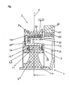
- the drive 1 of the decoupled pulley is effected by a centrally located hub ring 7, which is non-rotatably mounted on a crankshaft of an internal combustion engine, not shown here
- the torque curve 4 is carried by the hub ring 7 to the spring element 5, which consists of an elastomeric material and the hub ring 7 moselastisch with the inner support sleeve 11 connects.
- the spring element 5 is vulcanized with the hub ring 7 and the inner support sleeve 11. Torsional irregularities of the crankshaft, which are introduced by the hub ring 7 in the decoupled pulley, are already reduced by the torsionally elastic spring element 5 in the circumferential direction.
- the torque curve extends over the overrunning clutch 6, which is formed in the embodiment shown here as a wrap spring freewheel 9.
- the wrap spring freewheel 9 is connected downstream of the spring element 5 in a functional series connection, so that the rotational irregularities are largely kept away from the wrap spring freewheel 9 by the spring element 5.
- the wrap spring freewheel 9 is arranged in the radial direction between the inner support sleeve 11 and the radially inner axial projection 12, wherein the installation space, in which the wrap spring freewheel 9 is installed, filled with grease and sealed by the sealing rings 15, 16 from the environment.
- torque is transmitted via the wrap spring freewheel 9 to the pulley body 8, which forms the output 2.
- the pulley body 8 can drive an auxiliary unit, not shown here, of an internal combustion engine by means of a belt.
- the inner support sleeve 11 has a radially outwardly extending support collar 17 to which the radial projection 14 of the pulley body 8 by means of the Axialgleitlagers 18 applies.
- a flywheel ring 21 is arranged, which is connected by the spring body 20 with the guide flange 19.
- the guide flange 19 is arranged in the cavity of the C-shaped pulley body 8 and guided within the cavity in the radial and axial directions.
- This guidance is effected by means of the bearing 22, which is formed by an L-shaped sliding bearing 23, wherein the sliding bearing 23 is connected by the elastomer track 24 with the inner periphery of the radially outer axial projection 13.
- the guide of the flywheel ring 21 in the axial direction is effected by the radial projection 14 and the sliding bearing 23, which at least partially covers the radial projection 14 in the radial direction.
Landscapes
- Engineering & Computer Science (AREA)
- General Engineering & Computer Science (AREA)
- Mechanical Engineering (AREA)
- Physics & Mathematics (AREA)
- Acoustics & Sound (AREA)
- Aviation & Aerospace Engineering (AREA)
- Pulleys (AREA)
Applications Claiming Priority (1)
| Application Number | Priority Date | Filing Date | Title |
|---|---|---|---|
| DE102012006285A DE102012006285A1 (de) | 2012-03-29 | 2012-03-29 | Entkoppelte Riemenscheibe |
Publications (1)
| Publication Number | Publication Date |
|---|---|
| EP2644936A2 true EP2644936A2 (fr) | 2013-10-02 |
Family
ID=47721927
Family Applications (1)
| Application Number | Title | Priority Date | Filing Date |
|---|---|---|---|
| EP13000488.0A Withdrawn EP2644936A2 (fr) | 2012-03-29 | 2013-01-31 | Poulie à courroie découplée |
Country Status (3)
| Country | Link |
|---|---|
| EP (1) | EP2644936A2 (fr) |
| CN (1) | CN103363017A (fr) |
| DE (1) | DE102012006285A1 (fr) |
Families Citing this family (4)
| Publication number | Priority date | Publication date | Assignee | Title |
|---|---|---|---|---|
| DE102015202531B3 (de) * | 2015-02-12 | 2015-12-17 | Schaeffler Technologies AG & Co. KG | Riemenscheibenentkoppler |
| DE102015224608B4 (de) | 2015-12-08 | 2021-02-04 | Schaeffler Technologies AG & Co. KG | Riemenscheibenentkoppler |
| DE102017003156A1 (de) | 2017-03-31 | 2018-10-04 | Süddeutsche Gelenkscheibenfabrik GmbH & Co. KG | Schwingungsentkoppelte Riemenscheibe |
| CN107387733A (zh) * | 2017-09-13 | 2017-11-24 | 张家港保税区通勤精密机械有限公司 | 一种可扭转减震的曲轴皮带盘 |
Citations (1)
| Publication number | Priority date | Publication date | Assignee | Title |
|---|---|---|---|---|
| DE102009014203A1 (de) | 2009-03-20 | 2010-09-23 | Schaeffler Technologies Gmbh & Co. Kg | Vorrichtung zur Dämpfung von Drehschwingungen |
Family Cites Families (5)
| Publication number | Priority date | Publication date | Assignee | Title |
|---|---|---|---|---|
| EP2273144B1 (fr) * | 2003-09-22 | 2012-11-28 | Litens Automotive Partnership | Découpleur de vilebrequin |
| DE102004035969C5 (de) * | 2004-07-23 | 2019-06-19 | Vibracoustic Gmbh | Entkoppelte Riemenscheibe |
| JP4903264B2 (ja) * | 2006-07-07 | 2012-03-28 | ダイコ ユーロペ ソシエタ ア レスポンサビリタ リミタータ | プーリーアセンブリ |
| BRPI0721251A2 (pt) * | 2007-02-15 | 2013-01-15 | Dayco Europe Srl | conjunto de polia com amortecedor tendo um dispositivo de seguranÇa |
| DE202007018714U1 (de) * | 2007-11-27 | 2009-03-19 | Metaldyne International Deutschland Gmbh | Entkoppelte Riemenscheibe |
-
2012
- 2012-03-29 DE DE102012006285A patent/DE102012006285A1/de not_active Withdrawn
-
2013
- 2013-01-31 EP EP13000488.0A patent/EP2644936A2/fr not_active Withdrawn
- 2013-03-28 CN CN2013101033652A patent/CN103363017A/zh active Pending
Patent Citations (1)
| Publication number | Priority date | Publication date | Assignee | Title |
|---|---|---|---|---|
| DE102009014203A1 (de) | 2009-03-20 | 2010-09-23 | Schaeffler Technologies Gmbh & Co. Kg | Vorrichtung zur Dämpfung von Drehschwingungen |
Also Published As
| Publication number | Publication date |
|---|---|
| DE102012006285A1 (de) | 2013-10-02 |
| CN103363017A (zh) | 2013-10-23 |
Similar Documents
| Publication | Publication Date | Title |
|---|---|---|
| DE112006001432B4 (de) | Antriebsvorrichtung für ein Hybridfahrzeug | |
| DE112007002872B4 (de) | Triebrad eines Nebenaggregatezugs eines Verbrennungsmotors | |
| WO2001071219A1 (fr) | Poulie decouplee des vibrations avec amortisseur viscostatique integre | |
| EP2724050B1 (fr) | Dispositif de transmission de couple de rotation | |
| DE102016207130A1 (de) | Schwingungsdämpfer | |
| WO2018158033A1 (fr) | Dispositif de transmission pour une boîte de vitesse d'un véhicule ou similaire | |
| WO2016091260A1 (fr) | Volant bimasse avec masse supplémentaire | |
| EP2644936A2 (fr) | Poulie à courroie découplée | |
| EP2853772B1 (fr) | Amortisseur d'oscillations de torsion | |
| DE102016211141B4 (de) | Riemenscheibenentkoppler | |
| WO2016192724A1 (fr) | Désaccoupleur à poulie à courroie comportant des coquilles de glissement | |
| DE102018113626A1 (de) | Dämpferriemenscheibe für eine Kurbelwelle | |
| DE102015210013A1 (de) | Einmassenschwungrad | |
| WO2018145820A1 (fr) | Arrangement de transmission de couple | |
| DE102017124082A1 (de) | Drehschwingungsisolationseinrichtung | |
| EP3156688B1 (fr) | Amortisseur de vibrations torsionnelles pour un vilebrequin | |
| WO2020007395A2 (fr) | Découpleur de poulie à courroie comprenant une denture de matage ainsi qu'entraînement à groupe auxiliaire et moteur d'entraînement avec un découpleur de poulie à courroie correspondant | |
| DE102013111271B4 (de) | Antriebsvorrichtung | |
| DE102018119629A1 (de) | 1Riemenscheibenentkoppler mit separaten Anschlagsbauteilen | |
| DE102017123782A1 (de) | Membranring einer Drehmomentübertragungseinheit mit integriertem Federelement | |
| DE102017128870A1 (de) | Drehschwingungsdämpfer mit einer schwingungsentkoppelten Fliehkraftpendelanordnung | |
| DE102013214512A1 (de) | Schwungradanordnung mit Fliehkraftpendel | |
| DE102009042682A1 (de) | Antriebsvorrichtung für zumindest einen Nebentrieb | |
| DE102018127487A1 (de) | Abdichtung eines Innenraums von einem Drehschwingungsdämpfer | |
| DE102017121244B3 (de) | Vorrichtung zur Übertragung einer Drehbewegung |
Legal Events
| Date | Code | Title | Description |
|---|---|---|---|
| PUAI | Public reference made under article 153(3) epc to a published international application that has entered the european phase |
Free format text: ORIGINAL CODE: 0009012 |
|
| AK | Designated contracting states |
Kind code of ref document: A2 Designated state(s): AL AT BE BG CH CY CZ DE DK EE ES FI FR GB GR HR HU IE IS IT LI LT LU LV MC MK MT NL NO PL PT RO RS SE SI SK SM TR |
|
| AX | Request for extension of the european patent |
Extension state: BA ME |
|
| STAA | Information on the status of an ep patent application or granted ep patent |
Free format text: STATUS: THE APPLICATION HAS BEEN WITHDRAWN |
|
| 18W | Application withdrawn |
Effective date: 20141223 |