EP2644953A2 - Dispositif à soupape de mélange d'eau - Google Patents
Dispositif à soupape de mélange d'eau Download PDFInfo
- Publication number
- EP2644953A2 EP2644953A2 EP13161477.8A EP13161477A EP2644953A2 EP 2644953 A2 EP2644953 A2 EP 2644953A2 EP 13161477 A EP13161477 A EP 13161477A EP 2644953 A2 EP2644953 A2 EP 2644953A2
- Authority
- EP
- European Patent Office
- Prior art keywords
- valve element
- water
- movable valve
- water channel
- hot
- Prior art date
- Legal status (The legal status is an assumption and is not a legal conclusion. Google has not performed a legal analysis and makes no representation as to the accuracy of the status listed.)
- Granted
Links
Images










Classifications
-
- F—MECHANICAL ENGINEERING; LIGHTING; HEATING; WEAPONS; BLASTING
- F16—ENGINEERING ELEMENTS AND UNITS; GENERAL MEASURES FOR PRODUCING AND MAINTAINING EFFECTIVE FUNCTIONING OF MACHINES OR INSTALLATIONS; THERMAL INSULATION IN GENERAL
- F16K—VALVES; TAPS; COCKS; ACTUATING-FLOATS; DEVICES FOR VENTING OR AERATING
- F16K11/00—Multiple-way valves, e.g. mixing valves; Pipe fittings incorporating such valves
- F16K11/02—Multiple-way valves, e.g. mixing valves; Pipe fittings incorporating such valves with all movable sealing faces moving as one unit
- F16K11/06—Multiple-way valves, e.g. mixing valves; Pipe fittings incorporating such valves with all movable sealing faces moving as one unit comprising only sliding valves, i.e. sliding closure elements
- F16K11/078—Multiple-way valves, e.g. mixing valves; Pipe fittings incorporating such valves with all movable sealing faces moving as one unit comprising only sliding valves, i.e. sliding closure elements with pivoted and linearly movable closure members
- F16K11/0782—Single-lever operated mixing valves with closure members having flat sealing faces
- F16K11/0787—Single-lever operated mixing valves with closure members having flat sealing faces with both the supply and the discharge passages being on the same side of the closure members
-
- E—FIXED CONSTRUCTIONS
- E03—WATER SUPPLY; SEWERAGE
- E03C—DOMESTIC PLUMBING INSTALLATIONS FOR FRESH WATER OR WASTE WATER; SINKS
- E03C1/00—Domestic plumbing installations for fresh water or waste water; Sinks
- E03C1/02—Plumbing installations for fresh water
- E03C1/04—Water-basin installations specially adapted to wash-basins or baths
Definitions
- the present invention relates to water mixing valve devices, and in particular to a water mixing valve device built in a water mixing faucet and capable of discharging or stopping discharging mixed water in which hot water supplied from a hot-water supply source and cold water supplied from a cold-water supply source are mixed.
- a water mixing valve device built in a water mixing faucet and capable of discharging or stopping discharging mixed water in which hot water supplied from a hot-water supply source and cold water supplied from a cold-water supply source are mixed
- those disposed within a single-lever water mixing faucet and provided with a stationary valve element having a hot water channel and a cold water channel respectively allowing hot water supplied from a hot-water supply source and cold water supplied from a cold-water supply source to pass therethrough, a movable valve element provided slidably with respect to the stationary valve element to form a hot/cold water passage unit, and an operating lever that causes the movable valve element to move for opening or closing, as described in Japanese Unexamined Utility Model Application Publication No. S60-86675 , Japanese Unexamined Utility Model Application Publication No. S55-92964 , and Japanese Unexamined Patent Application Publication No. 2010-185569 , for example.
- the movable valve element slides with respect to the stationary valve element so as to change an opening cross-sectional area of the hot water channel and the cold water channel of the stationary valve element, a ratio of hot water and cold water mixed in the hot/cold water passage unit in the movable valve element is controlled, and whereby the temperature of mixed water discharged from a water outlet of the water mixing faucet can be adjusted.
- the hot water channel and the cold water channel of the stationary valve element are arranged symmetrically taking a center line extending along a front-back direction of the stationary valve element as a symmetry axis, and when the operating lever is turned by the turning operation within the operation range in a plane parallel to a sliding surface of the stationary valve element to adjust the temperature of the mixed water, the movable valve element is caused to turn and slide along an upper surface of the stationary valve element regardless of whether the movable valve element is opened or closed.
- the hot/cold water passage unit of the movable valve element in a state in which the operating lever is positioned at a frequently-used discharge operation position in front of and in center in the horizontal direction of the water mixing faucet to allow only water to be discharged from the water outlet of the water mixing faucet, the hot/cold water passage unit of the movable valve element is required to communicate only with the cold water channel of the stationary valve element when the movable valve element is at the valve-opening position, and the hot/cold water passage unit of the movable valve element is required to communicate with neither of the hot water channel and the cold water channel of the stationary valve element when the movable valve element is at the valve-closed position, even if the movable valve element turns and slides with respect to the stationary valve element.
- the hot water channel of the stationary valve element has to be designed to be relatively narrow, or to be disposed spaced apart from a central axis of the casing extending along the front-back direction of the stationary valve element. This adversely results in, when discharging hot water from the water outlet of the water mixing faucet by positioning the operating lever at a discharge operation position on a hot-water side, a decreased flow rate of hot water passing through the hot water channel of the stationary valve element by an amount of narrowing of the hot water channel of the stationary valve element.
- a flow rate of water passing through a water heater upstream the hot water channel of the stationary valve element does not adversely reach a flow rate minimum required to ignite the water heater, and hot water may not be adversely supplied from the water heater to the hot water channel of the stationary valve element.
- An object of the present invention is thus to provide, in order to address the above problems of the conventional techniques, a user-friendly water mixing valve device capable of discharging only water at a frequently-used discharge operation position while securing a sufficient amount of water to be discharged from a water outlet of a water mixing faucet, and increasing a flow rate of hot water passing through a hot water channel of a stationary valve element when opening a movable valve element to discharge mixed water.
- the present invention provides a water mixing valve device built within a water mixing faucet, and configured to either discharge or stop discharging mixed water in which hot water supplied from a hot-water supply source and cold water supplied from a cold-water supply source are mixed, the water mixing valve device comprising: a casing disposed upstream of a water outlet of the water mixing faucet; a stationary valve element fixed within the casing, and having a hot water channel through which hot water supplied from the hot-water supply source flows and a cold water channel through which cold water supplied from the cold-water supply source flows; a movable valve element disposed within the casing, configured to slide with respect to the stationary valve element to open and close the hot water channel and the cold water channel of the stationary valve element, and having therein a hot/cold water passage unit for letting hot water and cold water that have respectively passed through the hot water channel and the cold water channel to pass therethrough; and an operating unit having one end attached to the movable valve element such that the movable valve element is moved and an open
- the sliding range of the movable valve element with respect to the stationary valve element when the turning operation of the operating unit is performed in a state in which the movable valve element is closed can be more restricted as compared to a state in which the movable valve element is opened. Accordingly, it is possible to prevent the movable valve element in the closed state from opening the hot water channel and the cold water channel of the stationary valve element by the turning operation of the operating unit.
- respective flow channels in the hot water channel and the cold water channel of the stationary valve element can be set to be larger than those in a state in which the sliding range of the movable valve element with respect to the stationary valve element is less restricted than the state in which the movable valve element is opened.
- the hot water channel and the cold water channel of the stationary valve element are provided asymmetrically from each other with respect to the central axis of the casing such that the maximum distance between the central axis extending in the front-back direction of the stationary valve element and the hot water channel is smaller than the maximum distance between the central axis of the casing and the cold water channel, the hot water channel of the stationary valve element can be positioned closer to the central axis the casing. Therefore, as compared to the case in which the hot water channel of the stationary valve element is not positioned closer to the central axis of the casing, it is possible to increase a flow rate of hot water that flows through the hot water channel of the stationary valve element when opening the movable valve element to discharge mixed water.
- the water mixing faucet device is user friendly, as being capable of discharging only cold water while securing a sufficient amount of water to be discharged from the water outlet of the water mixing faucet at the frequently-used discharge operation position, as well as of increasing a flow rate of hot water that flows through the hot water channel of the stationary valve element when opening the movable valve element to discharge mixed water.
- the central axis of the casing refers to a line extending from a point assumed as its front side, which is a most frequently-used position in a normal usage of the water mixing valve device and at which a user faces toward the device, to a point behind the device passing a central point of the casing, that is, on a side opposite of the user.
- a vertically downward direction that is most frequently-used is assumed to be the front side, and a line extending in a vertically upward direction from this point passing the central point of the casing is referred to as the central axis of the casing.
- the present invention provides a water mixing valve device built within a water mixing faucet, and configured to either discharge or stop discharging mixed water in which hot water supplied from a hot-water supply source and cold water supplied from a cold-water supply source are mixed, the water mixing valve device comprising: a casing disposed upstream of a water outlet of the water mixing faucet; a stationary valve element fixed within the casing, and having a hot water channel through which hot water supplied from the hot-water supply source flows and a cold water channel through which cold water supplied from the cold-water supply source flows; a movable valve element disposed within the casing, configured to slide with respect to the stationary valve element to open and close the hot water channel and the cold water channel of the stationary valve element, and having therein a hot/cold water passage unit for letting hot water and cold water that have respectively passed through the hot water channel and the cold water channel to pass therethrough; and an operating unit having one end attached to the movable valve element such that the movable valve element is moved and an open/close operation of the water mixing
- the sliding range of the movable valve element with respect to the stationary valve element can be more restricted as compared to the state in which the movable valve element is opened. Accordingly, it is possible to prevent the movable valve element in the closed state from opening the hot water channel and the cold water channel of the stationary valve element by the turning operation of the operating unit.
- respective flow channels in the hot water channel and the cold water channel of the stationary valve element can be set to be larger than those in the state in which the sliding range of the movable valve element with respect to the stationary valve element is less restricted than the state in which the movable valve element is opened.
- the first region is provided so as to be enclosed by the cold water channel inner edge provided within the cold water channel on the central side of the casing, the central axis extending in the front-back direction of the stationary valve element, and the perpendicular line from one end of the cold water channel inner edge of the cold water channel of the stationary valve element to the central axis of the casing, and the second region is provided symmetrically with respect to the first region taking the central axis of the casing as the symmetry axis, and at least a portion of the hot water channel of the stationary valve element is within the second region.
- the hot water channel of the stationary valve element can be positioned closer to the central axis of the casing without providing the hot water channel and the cold water channel of the stationary valve element symmetrically with respect to the central axis of the casing. Therefore, as compared to the case in which the hot water channel of the stationary valve element is not positioned closer to the central axis of the casing, it is possible to increase a flow rate of hot water that flows through the hot water channel of the stationary valve element when opening the movable valve element to discharge mixed water.
- the water mixing faucet device is user friendly, as being capable of discharging only cold water while securing a sufficient amount of water to be discharged from the water outlet of the water mixing faucet at the frequently-used discharge operation position, as well as of increasing a flow rate of hot water that flows through the hot water channel of the stationary valve element when opening the movable valve element to discharge mixed water.
- the hot/cold water passage unit of the movable valve element includes a cold water channel side edge provided for the stationary valve element on a side of the cold water channel and a hot water channel side edge provided for the stationary valve element on a side of the hot water channel so as to face against the cold water channel side edge
- the stationary valve element further includes a third region and a fourth region, the third region being defined so as to be enclosed by the cold water channel side edge of the hot/cold water passage unit of the movable valve element, the central axis, and the perpendicular line, the fourth region being provided symmetrically with respect to the third region taking the central axis as a symmetry axis, and at least a portion of the hot water channel side edge of the hot/cold water passage unit of the movable valve element is within the fourth region.
- the stationary valve element includes the third region provided so as to be enclosed by the cold water channel side edge of the hot/cold water passage unit of the movable valve element, the central axis of the casing, and the perpendicular line from one end of the cold water channel inner edge of the cold water channel of the stationary valve element to the central axis of the casing, and the fourth region provided symmetrically with respect to the third region taking the central axis of the casing as the symmetry axis. Further, at least a portion of the hot water channel side edge of the hot/cold water passage unit of the movable valve element is within the fourth region.
- the hot water channel of the stationary valve element can be positioned further closer to the central axis of the casing without providing the hot water channel and the cold water channel of the stationary valve element symmetrically with respect to the central axis of the casing. Therefore, as compared to the case in which the hot water channel of the stationary valve element is not positioned closer to the central axis of the casing, when opening the movable valve element to discharge mixed water, it is possible to increase the area of the portion through which the hot water channel of the stationary valve element and the hot/cold water passage unit of the movable valve element are communicated with each other, and to further increase the flow rate of hot water that flows from the hot water channel of the stationary valve element to the hot/cold water passage unit of the movable valve element.
- the hot water channel of the stationary valve element includes a mixed water passage side edge provided for the movable valve element on a side of the hot/cold water passage unit, and when the open/close operation of the movable valve element is performed in a state in which the operating unit is turned by the turning operation to a front side of the casing in the plane parallel to the sliding surface of the movable valve element, a distance between the mixed water passage side edge and the hot water channel side edge of the movable valve element is smaller when the movable valve element is at a valve-opening position than when the movable valve element is at a valve-closed position.
- the movable valve element when the movable valve element is at the valve-closed position in the state in which the operating unit is turned by the turning operation to the front side of the casing in the plane parallel to the sliding surface of the movable valve element, it is possible to maintain the distance between the mixed water passage side edge of the hot water channel of the stationary valve element and the hot water channel side edge of the movable valve element, i.e., the minimum distance therebetween to be large, and therefore it is possible to ensure water shutoff and to prevent water from leaking through the water outlet of the water mixing faucet device.
- the movable valve element when the movable valve element is at the valve-opening position in the state in which the operating unit is turned by the turning operation to the front side of the casing in the plane parallel to the sliding surface of the movable valve element, it is possible to decrease the distance between the mixed water passage side edge of the hot water channel of the stationary valve element and the hot water channel side edge of the movable valve element as much as possible. Accordingly, the cross-sectional area of the flow channel of the hot water channel of the stationary valve element can be set to be large.
- the area of the portion through which the hot water channel of the stationary valve element and the hot/cold water passage unit of the movable valve element are communicated with each other can be increased, and it is possible to further increase the flow rate of hot water that flows from the hot water channel of the stationary valve element to the hot/cold water passage unit of the movable valve element.
- both of the mixed water passage side edge of the hot water channel of the stationary valve element and the hot water channel side edge of the movable valve element are inclined so as to become closer to the central axis toward a direction in which the movable valve element moves from the valve-closed position to the valve-opening position.
- both of the mixed water passage side edge of the hot water channel of the stationary valve element and the hot water channel side edge of the movable valve element are inclined so as to become closer to the central axis of the casing toward a direction in which the movable valve element moves from the valve-closed position to the valve-opening position, when the movable valve element is at the valve-closed position in the state in which the operating unit is turned by the turning operation to the front side of the casing in the plane parallel to the sliding surface of the movable valve element, it is possible to maintain the distance between the mixed water passage side edge of the hot water channel of the stationary valve element and the hot water channel side edge of the movable valve element to be large.
- the area of the portion through which the hot water channel of the stationary valve element and the hot/cold water passage unit of the movable valve element are communicated with each other can be increased, and it is possible to further increase the flow rate of hot water that flows from the hot water channel of the stationary valve element to the hot/cold water passage unit of the movable valve element.
- the mixed water passage side edge of the hot water channel of the stationary valve element includes a first mixed water passage side edge positioned proximally to the central axis, a second mixed water passage side edge positioned distally from the central axis as compared to the first mixed water passage side edge, and a first stepped portion defined by the first mixed water passage side edge and the second mixed water passage side edge
- the hot water channel side edge of the hot/cold water passage unit of the movable valve element includes a first hot water channel side edge positioned proximally to the central axis, a second hot water channel side edge positioned distally from the central axis as compared to the first hot water channel side edge, and a second stepped portion defined by the first hot water channel side edge and the second hot water channel side edge.
- the mixed water passage side edge of the hot water channel of the stationary valve element includes the first stepped portion defined by the first mixed water passage side edge positioned proximally to the central axis of the casing, and the second mixed water passage side edge positioned distally from the central axis of the casing as compared to the first mixed water passage side edge
- the hot water channel side edge of the hot/cold water passage unit of the movable valve element includes the second stepped portion defined by the first hot water channel side edge positioned proximally to the central axis of the casing, and the second hot water channel side edge positioned distally from the central axis of stationary valve element as compared to the first hot water channel side edge.
- the movable valve element when the movable valve element is at the valve-closed position in the state in which the operating unit is turned by the turning operation to the front side of the casing in the plane parallel to the sliding surface of the movable valve element, it is possible to maintain the distance between the mixed water passage side edge of the hot water channel of the stationary valve element and the hot water channel side edge of the movable valve element to be large. Therefore, it is possible to ensure water shutoff and to prevent water from leaking through the water outlet of the water mixing faucet device.
- the movable valve element when the movable valve element is at the valve-opening position in the state in which the operating unit is turned by the turning operation to the front side of the casing in the plane parallel to the sliding surface of the movable valve element, it is possible to decrease the distance between the mixed water passage side edge of the hot water channel of the stationary valve element and the hot water channel side edge of the movable valve element as much as possible, and the cross-sectional area of the flow channel of the hot water channel of the stationary valve element can be set to be large.
- the water mixing faucet device is user friendly, as being capable of discharging only cold water while securing a sufficient amount of water to be discharged from the water outlet of the water mixing faucet at the frequently-used discharge operation position, as well as of increasing a flow rate of hot water that flows through the hot water channel of the stationary valve element when opening the movable valve element to discharge mixed water.
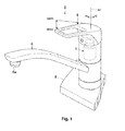
- Fig. 1 is a schematic three-quarter perspective view of a water mixing faucet device having a water mixing valve device according to the first embodiment of the present invention built therein.
- a water mixing faucet device 2 having a water mixing valve device 1 according to the first embodiment of the present invention built therein is a so-called single-lever water mixing faucet device capable of mixing hot water supplied from a hot-water supply source (not depicted) and cold water supplied from a cold-water supply source (not depicted), controlling and adjusting a flow rate and a temperature of the mixed water by operating a single handle lever 4, and discharging or stopping discharging the mixed water from a water outlet 6a of a spout 6.
- the water mixing faucet device 2 is placed on a countertop 8 of a sink in the kitchen or of a washbasin, and when the handle lever 4 is turned upward (a direction indicated by an arrow "open” in Fig. 1 ) by a turning operation, the water mixing faucet device 2 is set to a water discharge state in which mixed water can be discharged from the water outlet 6a of the spout 6 such that the more upward the handle lever 4 is turned, the more the flow rate of mixed water discharged from the water outlet 6a of the spout 6 is increased.
- the water mixing faucet device 2 is set to a water shutoff state in which discharging of mixed water from the water outlet 6a of the spout 6 is stopped.
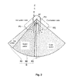
- Fig. 2 is a schematic plan view of the water mixing faucet device having the water mixing valve device according to the first embodiment of the present invention built therein, schematically illustrating a hot-water operation range for discharging only hot water, a cold-water operation range for discharging only cold water, and a mixed water operation range for discharging mixed water
- Fig. 3 is a front cross-sectional view illustrating the water mixing faucet device having the water mixing valve device according to the first embodiment of the present invention built therein.
- an operation range R in which the handle lever 4 is turned by the turning operation in the horizontal direction includes a hot-water operation range R1, a cold-water operation range R2, and a mixed water operation range R3.
- a movable valve element 10 which will be described in detail later of the water mixing valve device 1 opens only a hot water channel 12a of a stationary valve element 12 which will be described in detail later of the water mixing valve device 1, allows only hot water to flow into a hot/cold water passage unit 10a of the movable valve element 10 from the hot water channel 12a of the stationary valve element 12, and causes only hot water to be discharged from the water outlet 6a of the water mixing faucet device 2.
- the movable valve element 10 opens only a cold water channel 12b of the stationary valve element 12, allows only cold water to flow into the hot/cold water passage unit 10a of the movable valve element 10 from the cold water channel 12b of the stationary valve element 12, and causes only cold water to be discharged from the water outlet 6a of the water mixing faucet device 2.
- the mixed water operation range R3 is a region, when the handle lever 4 is turned by the turning operation to the hot-water side from a substantially-central operating position P3 in front of the water mixing faucet device 2 toward the hot-water operation range R1 (the direction indicated by the arrow H illustrated in Fig. 1 and Fig.
- the movable valve element 10 opens the hot water channel 12a and the cold water channel 12b of the stationary valve element 12, and hot water and cold water that flow into the hot/cold water passage unit 10a of the movable valve element 10 respectively from the hot water channel 12a and the cold water channel 12b of the stationary valve element 12 are mixed and discharged through the water outlet 6a of the water mixing faucet device 2.
- a region within the cold-water operation range R2 on a side of the mixed water operation range R3 corresponds to a frontal region in which the water mixing faucet device 2 is frequently used, and thus only water is discharged from the water outlet 6a of the water mixing faucet device 2 when the handle lever 4 is positioned at the operating position P3, which is substantially central position on a frontal side.
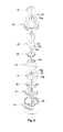
- Fig. 4 is an exploded perspective view illustrating the water mixing valve device according to the first embodiment of the present invention.
- the water mixing valve device 1 is provided with, from bottom up, a lower casing member 14, the stationary valve element 12, the movable valve element 10, a movable valve element guiding member 16, an operating lever holding member 18, a sealing member 20, an operating lever member 22, a upper casing member 24, and an operating lever upper connecting member 26.
- Fig. 5 is a plan view illustrating a lower casing member and a stationary valve element of the water mixing valve device according to the first embodiment of the present invention.
- the lower casing member 14 is connected to upper ends (downstream-side ends) of a hot water channel 2a and a cold water channel 2b that extend upward and downward through the water mixing faucet device 2, and the stationary valve element 12 is fixed within the lower casing member 14.
- the stationary valve element 12 is provided with, on its rear side, a water mixing channel 12c through which hot water and/or cold water that have passed through the hot/cold water passage unit 10a of the movable valve element 10 passes.
- the lower casing member 14 is provided with, at a portion under the water mixing channel 12c of the stationary valve element 12 and adjacent to a rear end 14a of the lower casing member 14 within the lower casing member 14, a water mixing channel 14b that communicates with the water mixing channel 12c of the stationary valve element 12.
- the hot water channel 12a and the cold water channel 12b provided through the stationary valve element 12 are respectively connected with the hot water channel 2a and the cold water channel 2b within the water mixing faucet device 2.
- the hot water channel 12a and the cold water channel 12b of the stationary valve element 12 are provided in shapes different from each other and asymmetrically with respect to a central axis A2 of the stationary valve element 12 such that a maximum distance L1 is smaller than a maximum distance L2; the maximum distance L1 is a length of a perpendicular line from an outermost position of the hot water channel 12a of the stationary valve element 12 (a leftmost position of the hot water channel 12a in Fig.
- the maximum distance L2 is a length of a perpendicular line from an outermost position of the cold water channel 12b of the stationary valve element 12 (a rightmost position of the cold water channel 12b in Fig. 5 ) to the central axis A2 of the stationary valve element 12.
- a guiding projection 28 as guiding means for guiding sliding and turning of the movable valve element 10 with respect to the stationary valve element 12 is provided so as to project inwardly.
- a central axis 28a of the guiding projection 28 is set obliquely at a predetermined angle ⁇ in a horizontal plane with respect to the central axis A2 extending along the front-back direction of the stationary valve element 12.
- the central axis A2 passes a center O of the lower casing member 14 and a portion near a hot-water side end 12d of the cold water channel 12b of the stationary valve element 12.
- a central point of a connecting section 22a of the operating lever member 22 in a water shutoff state is positioned above the center O of the lower casing member 14.
- the connecting section 22a is attached to an attachment hole 16a of the movable valve element guiding member 16 that will be later described in detail.
- the central axis A2 passes a point at which a central point of the connecting section 22a of the operating lever member 22 is projected as the center O and the portion near the hot-water side end 12d of the cold water channel 12b of the stationary valve element 12.
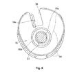
- Fig. 6 is a plan view illustrating the movable valve element and the movable valve element guiding member of the water mixing valve device according to the first embodiment of the present invention.
- the movable valve element 10 is provided slidably and turnably on the stationary valve element 12.
- the movable valve element guiding member 16 configured to guide the sliding and turning of the movable valve element 10 with respect to the stationary valve element 12 is fixed on the movable valve element 10.
- the movable valve element guiding member 16 is provided with a guiding groove 30 as guiding means, in which the guiding projection 28 of the lower casing member 14 can be inserted and fitted in a state in which the movable valve element guiding member 16 is attached within the lower casing member 14 along with the movable valve element 10.
- the movable valve element 10 and the movable valve element guiding member 16 are provided for example as separate members, the movable valve element 10 and the movable valve element guiding member 16 can be provided integrally to form a single member.
- the movable valve element guiding member 16 is provided with, at its substantial center, a cylindrical projecting portion 16b projecting upward and defining the attachment hole 16a in and to which the substantially-hemispherical connecting section 22a provided for a lower end of the operating lever member 22 is inserted and attached.
- a lower surface of the movable valve element 10 constitutes a sliding surface 10b with which the movable valve element 10 slides along an upper surface of the stationary valve element 12, and it is possible to open and close the movable valve element 10 by turning the operating lever member 22 in a plane perpendicular to the sliding surface 10b.
- a plane section S1 (see Fig. 6 ) of the attachment hole 16a of the movable valve element guiding member 16 is provided substantially in a circular cross-sectional shape that corresponds to the substantially hemispherical shape of the connecting section 22a of the operating lever member 22, so that turning the operating lever member 22 about the central axis A3 when the movable valve element 10 is in the closed state causes the connecting section 22a of the operating lever member 22 to turn idly with respect to the attachment hole 16a of the movable valve element guiding member 16.
- the substantially hemispherical connecting section 22a of the operating lever member 22 presses the attachment hole 16a of the movable valve element guiding member 16 to a predetermined horizontal direction to cause the movable valve element 10 to be turned and moved, along with the movable valve element guiding member 16, with respect to the stationary valve element 12.
- the movable valve element 10 is caused to be in an opened state, and at least one of the hot water channel 12a and the cold water channel 12b of the stationary valve element 12 is opened.
- the operating lever holding member 18 is interposed between the operating lever member 22 and the movable valve element guiding member 16.
- the operating lever holding member 18 is provided with, at its central portion, an elongate fitting hole 18a in which a rectangular fitting section 22b provided above the connecting section 22a of the operating lever member 22 can be inserted and fitted.
- the fitting section 22b of the operating lever member 22 is movable along the elongate fitting hole 18a during an open/close operation of the movable valve element 10 by the operating lever member 22.
- the operating lever holding member 18 is turnable together with the operating lever member 22 within the predetermined range of turning angle.
- the sealing member 20 illustrated in Fig. 4 is provided between a ball section 22c of the operating lever member 22 provided in a ball shape above the fitting section 22b of the operating lever member 22 and an attachment hole 24a provided in substantial center of the upper casing member 24, and configured to liquid-tightly seal an interior and an exterior of the upper casing member 24.
- a connecting section 4a of the handle lever 4 can be attached on top of it in a state in which the operating lever upper connecting member 26 is attached over the operating lever member 22.
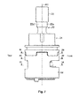
- Fig. 7 is a side view of the water mixing valve device according to the first embodiment of the present invention, illustrating a state in which the operating lever member is placed at an operating position on a side of the mixed water operation range within the cold-water operation range and the movable valve element is closed.
- Fig. 8 is a cross-sectional view taken along line VIII-VIII in Fig. 7
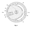
- Fig. 9 is a cross-sectional view taken along line IX-IX in Fig. 7
- Fig. 10 is a cross-sectional view taken along line X-X in Fig. 7 .
- the longitudinal central axis A3 of the operating lever member 22 matches the central axis A1 of the water mixing faucet device 2 extending in the vertical direction and the operating lever member 22 is upright.
- the operating lever holding member 18 is provided with, below the elongate fitting hole 18a, an elongate guiding hole 18b whose cross-sectional shape is oval extending backward from a central portion of a lower section of the operating lever holding member 18.
- the elongate guiding hole 18b of the operating lever holding member 18 is configured to guide the cylindrical projecting portion 16b of the movable valve element guiding member 16.
- the movable valve element guiding member 16 and the movable valve element 10 thereunder are positioned at a portion on a backmost side within the lower casing member 14, and the movable valve element 10 closes both of the hot water channel 12a and the cold water channel 12b of the stationary valve element 12.
- the guiding projection 28 of the lower casing member 14 is inserted into and fitted in substantially throughout the guiding groove 30 of the movable valve element guiding member 16.
- Fig. 11 is a side view of the water mixing valve device according to the first embodiment of the present invention, illustrating the state in which the operating lever member is placed at an operating position on the side of the mixed water operation range within the cold-water operation range and the movable valve element is opened.
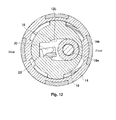
- Fig. 12 is a cross-sectional view taken along line XII-XII in Fig. 11
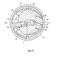
- Fig. 13 is a cross-sectional view taken along line XIII-XIII in Fig. 11
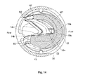
- Fig. 14 is a cross-sectional view taken along line XIV-XIV in Fig. 11 .
- the longitudinal central axis A3 of the operating lever member 22 is inclined backward by a predetermined angle ⁇ with respect to the central axis A1 of the water mixing faucet device 2 extending in the vertical direction.
- the movable valve element guiding member 16 and the movable valve element 10 thereunder are positioned generally on a frontmost side within the lower casing member 14, the movable valve element 10 keeps the hot water channel 12a of the stationary valve element 12 closed and partially opens only the cold water channel 12b of the stationary valve element 12.
- mixed water that have passed through the hot/cold water passage unit 10a of the movable valve element 10 from the partially opened cold water channel 12b of the stationary valve element 12 flows to the water mixing channel 14b of the lower casing member 14 through the water mixing channel 12c of the stationary valve element 12.
- an outline of the movable valve element guiding member 16 attached to the movable valve element 10 in the closed state illustrated in Fig. 9 is represented by a dashed line 16'
- an outline of the movable valve element guiding member 16 attached to the movable valve element 10 in transition from the closed state to the opened state is represented by a dashed line 16".
- a part of the guiding groove 30 of the movable valve element guiding member 16 generally moves forward while in contact with the guiding projection 28 of the lower casing member 14, and while turning toward a direction indicated by an arrow B1 in Fig.
- FIG. 14 an outline of the movable valve element 10 in the closed state illustrated in Fig. 10 is represented by a dashed line 10', and an outline of the movable valve element 10 in transition from the closed state to the opened state is represented by a dashed line 10". As illustrated in Fig. 14 , an outline of the movable valve element 10 in the closed state illustrated in Fig. 10 is represented by a dashed line 10', and an outline of the movable valve element 10 in transition from the closed state to the opened state is represented by a dashed line 10". As illustrated in Fig.
- the hot/cold water passage unit 10a of the movable valve element 10 generally slides forward with respect to the stationary valve element 12 while the movable valve element 10 keeps the hot water channel 12a of the stationary valve element 12 closed, and moves relatively toward the hot-water side (the side of the hot water channel 12a of the stationary valve element 12) while turning toward a direction indicated by an arrow B2 in Fig. 14 in a horizontal plane.
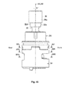
- Fig. 15 is a side view of the water mixing valve device according to the first embodiment of the present invention, illustrating a state in which the operating lever member is placed at a cold-water-side-most operating position within the cold-water operation range and the movable valve element is closed.
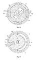
- Fig. 16 is a cross-sectional view taken along line XVI-XVI in Fig. 15
- Fig. 17 is a cross-sectional view taken along line XVII-XVII in Fig. 15
- Fig. 18 is a cross-sectional view taken along line XVIII-XVIII in Fig. 15 .
- the longitudinal central axis A3 of the operating lever member 22 matches the central axis A1 of the water mixing faucet device 2 extending in the vertical direction and the operating lever member 22 is upright.
- a front surface 26a of the operating lever upper connecting member 26 and a front surface 22e of an attachment section 22d of the operating lever member 22 to which the operating lever upper connecting member 26 is attached that are illustrated in Fig. 7 are turned in a counterclockwise direction by a predetermined angle ⁇ centering the central axis A3 viewed from above.
- the operating lever holding member 18 is configured to turn, together with the operating lever member 22, by the predetermined angle ⁇ centering the central axis A3, and a long side of the elongate guiding hole 18b of the operating lever holding member 18 illustrated in Fig. 16 is inclined by the predetermined angle ⁇ with respect to the central axis A2 extending in the front-back direction of the lower casing member 14.
- the connecting section 22a of the operating lever member 22 is caused to turn idly with respect to the attachment hole 16a of the movable valve element guiding member 16 even if the operating lever member 22 is turned about the central axis A3, and therefore the movable valve element 10 and the movable valve element guiding member 16 may not be turned about the central axis A3.
- a part of a diagonally backward left region in an outer circumferential surface of the cylindrical projecting portion 16b of the movable valve element guiding member 16 in Fig. 16 is in contact with a diagonally backward left region in an inner circumferential surface of the guiding hole 18b of the operating lever holding member 18 in Fig. 16 .
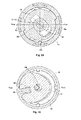
- Fig. 19 is a side view of the water mixing valve device according to the first embodiment of the present invention, illustrating a state in which the operating lever member is placed at the cold-water-side-most operating position within the cold-water operation range and the movable valve element is opened.
- Fig. 20 is a cross-sectional view taken along line XVIII-XVIII in Fig. 19
- Fig. 21 is a cross-sectional view taken along line XXI-XXI in Fig. 19
- Fig. 22 is a cross-sectional view taken along line XXII-XXII in Fig. 19 .
- the longitudinal central axis A3 of the operating lever member 22 is inclined diagonally backward by a predetermined angle ⁇ with respect to the central axis A1 of the water mixing faucet device 2 extending in the vertical direction.
- FIG. 20 an outline of the projecting portion 16b of the movable valve element guiding member 16 in the state in which the operating lever member 22 illustrated in Fig. 17 is placed at the cold-water-side-most operating position P2 within the cold-water operation range R2 and the movable valve element 10 is opened is represented by a dashed line 16b'.
- the movable valve element guiding member 16 and the movable valve element 10 thereunder are positioned generally on a diagonally forward right side within the lower casing member 14 in Fig. 21 and Fig. 22 , and the movable valve element 10 keeps the hot water channel 12a of the stationary valve element 12 closed and partially opens only the cold water channel 12b of the stationary valve element 12. Further, cold water that have passed through the hot/cold water passage unit 10a of the movable valve element 10 from the partially opened cold water channel 12b of the stationary valve element 12 flows to the water mixing channel 14b of the lower casing member 14 through the water mixing channel 12c of the stationary valve element 12.
- the outline of the movable valve element guiding member 16 attached to the movable valve element 10 in the closed state illustrated in Fig. 17 is represented by the dashed line 16'
- the outline of the movable valve element guiding member 16 attached to the movable valve element 10 in transition from the closed state to the opened state is represented by the dashed line 16".
- a part of the guiding groove 30 of the movable valve element guiding member 16 generally moves diagonally forward right viewed from a front side of Fig. 21 while in contact with the guiding projection 28 of the lower casing member 14, and while turning toward a direction indicated by an arrow D1 in Fig.
- the outline of the movable valve element 10 in the closed state illustrated in Fig. 18 is represented by the dashed line 10'
- the outline of the movable valve element 10 in transition from the closed state to the opened state is represented by the dashed line 10".
- the hot/cold water passage unit 10a of the movable valve element 10 generally slides diagonally forward right viewed from a front side of Fig.
- Fig. 23 is a side view of the water mixing valve device according to the first embodiment of the present invention, illustrating a state in which the operating lever member is placed at a hot-water-side-most operating position within the hot-water operation range and the movable valve element is closed.
- Fig. 24 is a cross-sectional view taken along line XXIV-XXIV in Fig. 23
- Fig. 25 is a cross-sectional view taken along line XXV-XXV in Fig. 23
- Fig. 26 is a cross-sectional view taken along line XXVI-XXVI in Fig. 23 .
- the longitudinal central axis A3 of the operating lever member 22 matches the central axis A1 of the water mixing faucet device 2 extending in the vertical direction and the operating lever member 22 is upright.
- FIG. 23 the front surface 26a of the operating lever upper connecting member 26 and the front surface 22e of an attachment section 22d of the operating lever member 22 to which the operating lever upper connecting member 26 is attached that are illustrated in Fig. 7 are turned in a clockwise direction by a predetermined angle ⁇ centering the central axis A3 viewed from above.
- the operating lever holding member 18 is configured to turn, together with the operating lever member 22, by the predetermined angle ⁇ centering the central axis A3, and the long side of the elongate guiding hole 18b of the operating lever holding member 18 illustrated in Fig. 24 is inclined by the predetermined angle ⁇ with respect to the central axis A2 extending in the front-back direction of the lower casing member 14.
- the connecting section 22a of the operating lever member 22 is caused to turn idly with respect to the attachment hole 16a of the movable valve element guiding member 16 even if the operating lever member 22 is turned about the central axis A3, and therefore the movable valve element 10 and the movable valve element guiding member 16 may not be turned about the central axis A3.
- the parts of the diagonally backward left region and the diagonally forward right region in the outer circumferential surface of the cylindrical projecting portion 16b of the movable valve element guiding member 16 when viewed from the front side of Fig. 24 are respectively in contact with the parts of the diagonally backward left region and the diagonally forward right region in the inner circumferential surface of the guiding hole 18b of the operating lever holding member 18 when viewed from the front side of Fig. 24 .
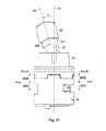
- Fig. 27 is a side view of the water mixing valve device according to the first embodiment of the present invention, illustrating a state in which the operating lever member is placed at the hot-water-side-most operating position within the hot-water operation range and the movable valve element is opened.
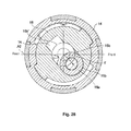
- Fig. 28 is a cross-sectional view taken along line XXVIII-XXVIII in Fig. 27
- Fig. 29 is a cross-sectional view taken along line XXIX-XXIX in Fig. 27
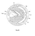
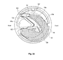
- Fig. 30 is a cross-sectional view taken along line XXX-XXX in Fig. 27 .
- the longitudinal central axis A3 of the operating lever member 22 is inclined diagonally backward by a predetermined angle ⁇ with respect to the central axis A1 of the water mixing faucet device 2 extending in the vertical direction.
- FIG. 28 an outline of the projecting portion 16b of the movable valve element guiding member 16 in the state in which the operating lever member 22 illustrated in Fig. 24 is placed at the hot-water-side-most operating position P1 within the hot-water operation range R1 and the movable valve element 10 is opened is represented by a dashed line 16b'.
- the movable valve element guiding member 16 and the movable valve element 10 thereunder are positioned generally on a diagonally forward left side within the lower casing member 14 viewed from a front side of Fig. 29 and Fig. 30 , and the movable valve element 10 keeps the cold water channel 12b of the stationary valve element 12 closed and partially opens only the hot water channel 12a of the stationary valve element 12. Further, hot water that have passed through the hot/cold water passage unit 10a of the movable valve element 10 from the partially opened hot water channel 12a of the stationary valve element 12 flows to the water mixing channel 14b of the lower casing member 14 through the water mixing channel 12c of the stationary valve element 12.
- the outline of the movable valve element guiding member 16 attached to the movable valve element 10 in the closed state illustrated in Fig. 25 is represented by the dashed line 16'
- the outline of the movable valve element guiding member 16 attached to the movable valve element 10 in transition from the closed state to the opened state is represented by the dashed line 16".
- a part of the guiding groove 30 of the movable valve element guiding member 16 generally moves diagonally forward left viewed from a front side of Fig. 25 while in contact with the guiding projection 28 of the lower casing member 14, and while turning toward a direction indicated by an arrow E1 in Fig.
- the outline of the movable valve element 10 in the closed state illustrated in Fig. 26 is represented by the dashed line 10'
- the outline of the movable valve element 10 in transition from the closed state to the opened state is represented by the dashed line 10".
- the hot/cold water passage unit 10a of the movable valve element 10 generally slides diagonally forward left viewed from the front side of Fig.
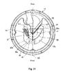
- Fig. 31 is a view of a first region and a second region of the stationary valve element in the plan view of Fig. 5 illustrating the lower casing member and the stationary valve element of the water mixing valve device according to the first embodiment of the present invention.
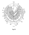
- Fig. 32 is a view of the stationary valve element and the movable valve element of the water mixing valve device according to the first embodiment of the present invention, illustrating a first region to a fourth region of the stationary valve element in a state in which the operating lever member is placed at an operating position within any of the cold-water operation range, the hot-water operation range, and the mixed water operation range and the movable valve element is closed.
- Fig. 32 is a view of the stationary valve element and the movable valve element of the water mixing valve device according to the first embodiment of the present invention, illustrating a first region to a fourth region of the stationary valve element in a state in which the operating lever member is placed at an operating position within any of the cold-water operation range, the hot-water operation range, and the mixed water
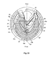
- FIG. 33 is a view of the stationary valve element and the movable valve element of the water mixing valve device according to the first embodiment of the present invention, illustrating the first region to the fourth region of the stationary valve element in the state in which the operating lever member is placed at the operating position on the side of the mixed water operation range within the cold-water operation range and the movable valve element is opened.
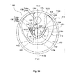
- Fig. 34 is a view of the stationary valve element and the movable valve element of the water mixing valve device according to the first embodiment of the present invention, illustrating the first region to the fourth region of the stationary valve element in the state in which the operating lever member is placed at the hot-water-side-most operating position within the hot-water operation range and the movable valve element is opened.
- the stationary valve element 12 includes a first region r1 and a second region r2; the first region r1 is defined so as to be enclosed by an inner edge 32 on a side of the center O of the lower casing member 14 of the cold water channel 12b, the central axis A2 extending in the front-back direction of the stationary valve element 12, and a perpendicular line V1 from a rear end 32a of the inner edge 32 of the cold water channel 12b to the central axis A2, and the second region r2 is provided symmetrically with respect to the first region r1 taking the central axis A2 of the stationary valve element 12 as a symmetry axis.
- a partial region h1 of the hot water channel 12a of the stationary valve element is provided within the second region r2.
- the hot/cold water passage unit 10a of the movable valve element 10 includes a cold water channel side edge 34 provided for the stationary valve element 12 on a side of the cold water channel 12b and a hot water channel side edge 36 provided for the stationary valve element 12 on a side of the hot water channel 12a so as to face against the cold water channel side edge 34.
- the stationary valve element 12 includes a third region r3 and a fourth region r4; the third region r3 is defined so as to be enclosed by the cold water channel side edge 34 of the hot/cold water passage unit 10a of the movable valve element 10, the central axis A2 of the stationary valve element 12, and the perpendicular line V1 from the rear end 32a of the inner edge 32 of the cold water channel 12b to the central axis A2, and the fourth region r4 is provided symmetrically with respect to the third region r3 taking the central axis A2 of the stationary valve element 12 as a symmetry axis.
- a partial region of the hot water channel side edge 36 of the hot/cold water passage unit 10a of the movable valve element 10 is provided within the fourth region r4.
- the hot water channel 12a of the stationary valve element 12 is positioned closer to the central axis A2 of the stationary valve element 12 without providing the hot water channel 12a and the cold water channel 12b of the stationary valve element 12 symmetrically with respect to the central axis A2 of the stationary valve element 12. Therefore, as compared to a case in which the hot water channel 12a of the stationary valve element 12 is not positioned closer to the central axis A2 of the stationary valve element 12, it is possible to increase a flow rate of hot water that flows through the hot water channel 12a of the stationary valve element 12 when opening the movable valve element 10 to discharge mixed water.
- the hot water channel 12a of the stationary valve element 12 includes an inner edge 38 provided on a side of the hot/cold water passage unit 10a of the movable valve element 10. Further, it is assumed that a valve-closed position and a valve-opening position of the movable valve element 10 are P4 and P5, respectively, when the open/close operation of the movable valve element 10 is performed in the state in which the handle lever 4 is placed at the operating position P3 that is frequently used and positioned substantially in the center on the front side.
- a distance d1 between the inner edge 38 of the hot water channel 12a of the stationary valve element 12 and the hot water channel side edge 36 of the hot/cold water passage unit 10a of the movable valve element 10 where the inner edge 38 and the hot water channel side edge 36 are closest when the movable valve element 10 is at the valve-opening position P5 is set to be smaller than a distance d2 between the inner edge 38 of the hot water channel 12a of the stationary valve element 12 and the hot water channel side edge 36 of the hot/cold water passage unit 10a of the movable valve element 10 where the inner edge 38 and the hot water channel side edge 36 are closest when the movable valve element 10 is at the valve-closed position P4 (see Fig. 32 ).
- both of the inner edge 38 of the hot water channel 12a of the stationary valve element 12 and the hot water channel side edge 36 of the hot/cold water passage unit 10a of the movable valve element 10 are inclined so as to become closer to the central axis A2 of the stationary valve element 12 either toward a direction in which the movable valve element 10 moves from the valve-closed position P4 (see Fig. 32 ) to the valve-opening position P5 (see Fig. 33 ), or a direction from back to front of the movable valve element 10.
- a sliding range in which the movable valve element 10 slides with respect to the stationary valve element 12 is more restricted than that in the case in which the movable valve element 10 is at the valve-opening position P5 or P6, and the respective flow channels in the hot water channel 12a and the cold water channel 12b of the stationary valve element 12 can be set to be larger than those in a state in which the sliding range of the movable valve element 10 with respect to the stationary valve element 12 is less restricted than in the state in which the movable valve element is opened.
- the handle lever 4 of the water mixing faucet device 2 is turned about the central axis A1 to be placed at the operating position P3 that is frequently used and positioned substantially in the center on the front side of the water mixing faucet device 2, and the handle lever 4 is operated to the direction indicated by the arrow "open", as illustrated in Fig. 11 through Fig. 14 , operating the operating lever member 22 of the water mixing valve device 1 causes the movable valve element 10 to slide with respect to the stationary valve element 12 while turning toward the hot-water side, and to open only the cold water channel 12b of the stationary valve element 12 while maintaining the hot water channel 12a of the stationary valve element 12 in the closed state.
- the cold water that flows from the cold water channel 12b of the stationary valve element 12 through the hot/cold water passage unit 10a of the movable valve element 10 is discharged from the water outlet 6a of the spout 6 of the water mixing faucet device 2 through the water mixing channel 12c of the stationary valve element 12.
- the cold water that flows from the cold water channel 12b of the stationary valve element 12 through the hot/cold water passage unit 10a of the movable valve element 10 is discharged from the water outlet 6a of the spout 6 of the water mixing faucet device 2 through the water mixing channel 12c of the stationary valve element 12.
- the hot water that flows from the hot water channel 12a of the stationary valve element 12 through the hot/cold water passage unit 10a of the movable valve element 10 is discharged from the water outlet 6a of the spout 6 of the water mixing faucet device 2 through the water mixing channel 12c of the stationary valve element 12.
- moving the movable valve element 10 in the closed state to the opened state by operating the handle lever 4 and the operating lever member 22 when the handle lever 4 and the operating lever member 22 are at the operating position P3 on the side of the mixed water operation range R3 within the cold-water operation range R2 allows the movable valve element 10 to move and turn with respect to the stationary valve element 12 toward the direction in which the opening cross-sectional area of the cold water channel 12b of the stationary valve element 12 is increased while maintaining the hot water channel 12a of the stationary valve element 12 closed.
- a guiding direction of the guiding projection 28 of the lower casing member 14 as guiding means configured to guide the movement of the movable valve element 10 and the movable valve element 10 guided by the guiding groove 30 of the movable valve element guiding member 16 is set to be a direction inclined so as to become closer to the central axis A2 extending in the front-back direction of the stationary valve element 12.
- the movable valve element 10 is guided by the guiding projection 28 of the lower casing member 14 and the guiding groove 30 of the movable valve element guiding member 16, and moves and turns with respect to the stationary valve element 12.
- the movable valve element 10 can be opened and closed efficiently in a relatively small space within the lower casing member 14, and it is possible to downsize the water mixing valve device 1.
- moving the movable valve element 10 in the closed state to the opened state by operating the handle lever 4 and the operating lever member 22 when the handle lever 4 and the operating lever member 22 are on the side of the mixed water operation range R3 within the cold-water operation range R2 allows the movable valve element 10 to move and turn with respect to the stationary valve element 12 toward the direction in which the opening cross-sectional area of the cold water channel 12b of the stationary valve element 12 is increased while maintaining the hot water channel 12a of the stationary valve element 12 closed to move the hot/cold water passage unit 10a of the movable valve element 10 toward the side of the cold water channel 12b of the stationary valve element 12. This is not advantageous for discharging hot water.
- the hot water channel 12a and the cold water channel 12b of the stationary valve element 12 are provided in shapes different from each other and asymmetrically with respect to a central axis A2 of the stationary valve element 12 such that the maximum distance L1 is smaller than the maximum distance L2; the maximum distance L1 is the length of the perpendicular line from the outermost position of the hot water channel 12a of the stationary valve element 12 (the leftmost position of the hot water channel 12a in Fig.
- the maximum distance L2 is the length of the perpendicular line from the outermost position of the cold water channel 12b of the stationary valve element 12 (the rightmost position of the cold water channel 12b in Fig. 5 ) to the central axis A2 of the stationary valve element 12.
- the water mixing valve device 1 of this embodiment with the substantially hemispherical connecting section 22a of the operating lever member 22 and an attachment cross section of the attachment hole 16a, whose cross-sectional shape is substantially circular and in and to which the connecting section 22a is inserted and attached, of the movable valve element guiding member 16 above the movable valve element 10, in a state in which the movable valve element 10 is closed, turning the operating lever member 22 about the central axis A3 causes the operating lever member 22 to turn idly with respect to the attachment hole 16a of the movable valve element guiding member 16 and the movable valve element 10 may not be turned in the horizontal plane, and in a state in which the movable valve element 10 is opened, turning the operating lever member 22 about the central axis A3 causes the movable valve element 10 to move while turning with respect to the stationary valve element 12.
- the movable valve element 10 can be opened and closed efficiently.
- the range in which the movable valve element 10 slides with respect to the stationary valve element 12 is more restricted than that in the case in which the movable valve element 10 is at the valve-opening position P5 or P6. Accordingly, it is possible to prevent the movable valve element 10 in the closed state from opening the hot water channel 12a and the cold water channel 12b of the stationary valve element 12 by the turning operation of the handle lever 4.
- the respective flow channels in the hot water channel 12a and the cold water channel 12b of the stationary valve element 12 can be set to be larger than those in the case in which the movable valve element 10 is at the valve-opening position P5 or P6 and the range in which the movable valve element 10 slides with respect to the stationary valve element 12 is not restricted.
- the hot water channel 12a and the cold water channel 12b of the stationary valve element 12 are provided in shapes different from each other and asymmetrically with respect to the central axis A2 of the stationary valve element 12 such that the maximum distance L1 is smaller than the maximum distance L2; the maximum distance L1 is the length of the perpendicular line from the outermost position of the hot water channel 12a of the stationary valve element 12 (the leftmost position of the hot water channel 12a in Fig. 5 and Fig.
- the hot water channel 12a of the stationary valve element 12 can be positioned closer to the central axis A2 of the stationary valve element 12.
- an area of a portion through which the hot water channel 12a of the stationary valve element 12 and the hot/cold water passage unit 10a of the movable valve element 10 are communicated with each other can be increased, and it is possible to further increase the flow rate of hot water that flows from the hot water channel 12a of the stationary valve element 12 to the hot/cold water passage unit 10a of the movable valve element 10.
- the stationary valve element 12 includes the first region r1 and the second region r2; the first region r1 is defined so as to be enclosed by the inner edge 32 in the cold water channel 12b on the side of the center O of the lower casing member 14, the central axis A2 extending in the front-back direction of the stationary valve element 12, and the perpendicular line V1 from the rear end 32a of the inner edge 32 of the cold water channel 12b to the central axis A2, and the second region r2 is provided symmetrically with respect to the first region r1 taking the central axis A2 of the stationary valve element 12 as the symmetry axis.
- the partial region h1 of the hot water channel 12a of the stationary valve element 12 is provided within the second region r2. Accordingly, the hot water channel 12a of the stationary valve element 12 can be positioned closer to the central axis A2 of the stationary valve element 12 without providing the hot water channel 12a and the cold water channel 12b of the stationary valve element 12 symmetrically with respect to the central axis A2 of the stationary valve element 12. Therefore, as compared to the case in which the hot water channel 12a of the stationary valve element 12 is not positioned closer to the central axis A2 of the stationary valve element 12, it is possible to increase the flow rate of hot water that flows through the hot water channel 12a of the stationary valve element 12 when opening the movable valve element 10 to discharge mixed water.
- the area of the portion through which the hot water channel 12a of the stationary valve element 12 and the hot/cold water passage unit 10a of the movable valve element 10 are communicated with each other can be increased, and it is possible to further increase the flow rate of hot water that flows from the hot water channel 12a of the stationary valve element 12 to the hot/cold water passage unit 10a of the movable valve element 10.
- the stationary valve element 12 includes the third region r3 and the fourth region r4; the third region r3 is defined so as to be enclosed by the cold water channel side edge 34 of the hot/cold water passage unit 10a of the movable valve element 10, the central axis A2 of the stationary valve element 12, and the perpendicular line V1 from the rear end 32a of the inner edge 32 of the cold water channel 12b to the central axis A2, and the fourth region r4 is provided symmetrically with respect to the third region r3 taking the central axis A2 of the stationary valve element 12 as the symmetry axis.
- the partial region of the hot water channel side edge 36 of the hot/cold water passage unit 10a of the movable valve element 10 is provided within the fourth region r4. Accordingly, the hot water channel 12a of the stationary valve element 12 can be positioned closer to the central axis A2 of the stationary valve element 12 without providing the hot water channel 12a and the cold water channel 12b of the stationary valve element 12 symmetrically with respect to the central axis A2 of the stationary valve element 12.
- the distance d1 between the inner edge 38 of the hot water channel 12a of the stationary valve element 12 and the hot water channel side edge 36 of the hot/cold water passage unit 10a of the movable valve element 10 where the inner edge 38 and the hot water channel side edge 36 are closest when the movable valve element 10 is at the valve-opening position P5 (see Fig.
- both of the inner edge 38 of the hot water channel 12a of the stationary valve element 12 and the hot water channel side edge 36 of the hot/cold water passage unit 10a of the movable valve element 10 are inclined so as to become closer to the central axis A2 of the stationary valve element 12 either toward a direction in which the movable valve element 10 moves from the valve-closed position P4 (see Fig. 32 ) to the valve-opening position P5 (see Fig. 33 ), or a direction from back to front of the movable valve element 10.
- the area of the portion through which the hot water channel 12a of the stationary valve element 12 and the hot/cold water passage unit 10a of the movable valve element 10 are communicated with each other can be further increased, and it is possible to further increase the flow rate of hot water that flows from the hot water channel 12a of the stationary valve element 12 to the hot/cold water passage unit 10a of the movable valve element 10.
- Fig. 35 is a plan view illustrating a lower casing member and a movable valve element guiding member of a water mixing valve device according to the second embodiment of the present invention in a state in which an operating lever member is placed at an operating position on a side of a mixed water operation range within a cold-water operation range and a movable valve element is closed.
- Fig. 36 is a plan view illustrating a stationary valve element and the movable valve element of the water mixing valve device according to the second embodiment of the present invention in the state in which the operating lever member is placed at the operating position on the side of the mixed water operation range within the cold-water operation range and the movable valve element is closed.
- Fig. 36 is a plan view illustrating a stationary valve element and the movable valve element of the water mixing valve device according to the second embodiment of the present invention in the state in which the operating lever member is placed at the operating position on the side of the mixed water operation range within the cold-water operation range and the movable valve element is closed.
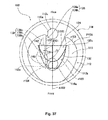
- FIG. 37 is a plan view illustrating a stationary valve element and the movable valve element of the water mixing valve device according to the second embodiment of the present invention in the state in which the operating lever member is placed at the operating position on the side of the mixed water operation range within the cold-water operation range and the movable valve element is opened.
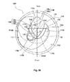
- Fig. 38 is a plan view illustrating the stationary valve element and the movable valve element of the water mixing valve device according to the second embodiment of the present invention in a state in which the operating lever member is placed at the hot-water-side-most operating position within the hot-water operation range and the movable valve element is opened.
- Fig. 38 is a plan view illustrating the stationary valve element and the movable valve element of the water mixing valve device according to the second embodiment of the present invention in a state in which the operating lever member is placed at the hot-water-side-most operating position within the hot-water operation range and the movable valve element is opened.
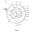
- 39 is a plan view illustrating the stationary valve element and the movable valve element of the water mixing valve device according to the second embodiment of the present invention in a state in which the operating lever member is placed at the cold-water-side-most operating position within the cold-water operation range and the movable valve element is opened.
- a movable valve element guiding member 116 built within a lower casing member 114 and configured to guide sliding of a movable valve element 110 with respect to a stationary valve element 112, and a guiding projection 128 provided on a rear end 114a of the lower casing member 114 on an inner circumference side and inserted and fitted into a guiding groove 130 of the movable valve element guiding member 116 are different from the movable valve element guiding member 16 and the guiding projection 28 in the water mixing valve device 1 according to the first embodiment of the present invention described above.
- the shape of a hot water channel 112a of the stationary valve element 112 built within the lower casing member 114 is different from that of the hot water channel 12a of the stationary valve element 12 of the water mixing valve device 1 according to the first embodiment of the present invention described above, and the shape of a hot water channel side edge 136 of a hot/cold water passage unit 110a of the movable valve element 110 is different from that of the hot water channel side edge 36 of the hot/cold water passage unit 10a of the movable valve element 10 in the water mixing valve device 1 according to the first embodiment of the present invention described above.
- the guiding projection 128 is provided so as to project forward from the rear end 114a of the lower casing member 114 on the inner circumference side, and a central axis 128a of the guiding projection 128 extends upward and downward parallelly to a central axis A102 extending in a front-back direction of the stationary valve element 112, and matches in a planar view illustrated in Fig. 35 . Therefore, in the state in which the handle lever 4 illustrated in Fig. 2 is placed at the operating position P3 that is frequently used and positioned substantially in the center on the front side, if the open/close operation of the movable valve element 110 is performed from a valve-closed position P104 (see Fig.
- an attachment hole 116a of the movable valve element guiding member 116 in which the connecting section 22a of the operating lever member 22 is attached moves forward, and while maintaining the state in which the guiding groove 130 of the movable valve element guiding member 116 is fitted with the guiding projection 128, the movable valve element guiding member 116 moves, along with the movable valve element 110, from the valve-closed position P104 (see Fig. 35 and Fig. 36 ) to the valve-opening position P105 (see Fig. 35 and Fig. 37 ) straightly forward without turning.
- the movable valve element 110 in the state in which the guiding groove 130 of the movable valve element guiding member 116 at the valve-opening position P105 is out of the fitting with the guiding projection 128, by further turning the handle lever 4 illustrated in Fig. 2 by the turning operation to the hot-water side operating position P1 or to the cold-water side operating position P2, the movable valve element 110 can turn and slide along an upper surface of the stationary valve element 112.
- an inner edge 138 of the hot water channel 112a of the stationary valve element 112 includes a first inner edge 138a, a second inner edge 138b, and a third inner edge 138c; the first inner edge 138a is positioned most proximally to the central axis A102 of the stationary valve element 112 and on a frontmost side in the inner edge 138, the second inner edge 138b is positioned more distally from the central axis A102 and more backward than the first inner edge 138a, and the third inner edge 138c is positioned most distally from the central axis A102 of the stationary valve element 112 and more backward than the second inner edge 138b.
- the inner edge 138 of the hot water channel 112a of the stationary valve element 112 further includes a first stepped portion 140 provided so as to connect a rear end of the first inner edge 138a and a front end of the second inner edge 138b, and a second stepped portion 142 provided so as to connect a rear end of the second inner edge 138b and a front end of the third inner edge 138c.
- the hot water channel side edge 136 of the hot/cold water passage unit 110a of the movable valve element 110 includes a first hot water channel side edge 136a and a second hot water channel side edge 136b; the first hot water channel side edge 136a is positioned proximally to the central axis A102 of the stationary valve element 112 and on the front side, and the second hot water channel side edge 136b is positioned more distally from the central axis A102 and more backward than the first hot water channel side edge 136a.
- the hot water channel side edge 136 of the hot/cold water passage unit 110a of the movable valve element 110 further includes a stepped portion 144 provided so as to connect a rear end of the first hot water channel side edge 136a and a front end of the second hot water channel side edge 136b.
- the stationary valve element 112 includes a first region r101 and a second region r102; the first region r101 is defined so as to be enclosed by an inner edge 132 on a side of a center O of the lower casing member 114 of the cold water channel 112b, the central axis A102 extending in the front-back direction of the stationary valve element 112, and a perpendicular line V101 from a rear end 132a of the inner edge 132 of the cold water channel 112b to the central axis A102, and the second region r102 is provided symmetrically with respect to the first region r101 taking the central axis A102 of the stationary valve element 112 as a symmetry axis.
- a partial region h101 of the hot water channel 112a of the stationary valve element is provided within the second region r102.
- the hot water channel 112a of the stationary valve element 112 is positioned closer to the central axis A102 of the stationary valve element 112 without providing the hot water channel 112a and the cold water channel 112b of the stationary valve element 112 symmetrically with respect to the central axis A102 of the stationary valve element 112. Therefore, as compared to a case in which the hot water channel 112a of the stationary valve element 112 is not positioned closer to the central axis A102 of the stationary valve element 112, it is possible to increase a flow rate of hot water that flows through the hot water channel 112a of the stationary valve element 112 when opening the movable valve element 110 to discharge mixed water.
- the stationary valve element 112 includes a third region r103 and a fourth region r104; the third region r103 is defined so as to be enclosed by a cold water channel side edge 134 of the hot/cold water passage unit 110a of the movable valve element 110, the central axis A102 of the stationary valve element 112, and the perpendicular line V101 from the rear end 132a of the inner edge 132 of the cold water channel 112b to the central axis A102, and the fourth region r104 is provided symmetrically with respect to the third region r103 taking the central axis A102 of the stationary valve element 112 as a symmetry axis.
- a partial region of the hot water channel side edge 136 of the hot/cold water passage unit 110a of the movable valve element 110 is provided within the fourth region r104.
- the hot water channel 112a of the stationary valve element 112 is positioned closer to the central axis A102 of the stationary valve element 112 without providing the hot water channel 112a and the cold water channel 112b of the stationary valve element 112 symmetrically with respect to the central axis A102 of the stationary valve element 112. Therefore, as compared to a case in which the hot water channel 112a of the stationary valve element 112 is not positioned closer to the central axis A102 of the stationary valve element 112, it is possible to increase a flow rate of hot water that flows through the hot water channel 112a of the stationary valve element 112 when opening the movable valve element 110 to discharge mixed water (see Fig. 38 ).
- a distance d101 (see Fig. 37 ) between the inner edge 138 of the hot water channel 112a of the stationary valve element 112 and the hot water channel side edge 136 of the hot/cold water passage unit 110a of the movable valve element 110 where the inner edge 138 and the hot water channel side edge 136 are closest when the movable valve element 110 is at the valve-opening position P105 (see Fig.
- the stationary valve element 112 includes the first region r101 and the second region r102; the first region r101 is defined so as to be enclosed by the inner edge 132 on the side of the center O of the lower casing member 114 of the cold water channel 112b, the central axis A102 extending in the front-back direction of the stationary valve element 112, and the perpendicular line V101 from the rear end 132a of the inner edge 132 of the cold water channel 112b to the central axis A102, and the second region r102 is provided symmetrically with respect to the first region r101 taking the central axis A102 of the stationary valve element 112 as the symmetry axis.
- the partial region h101 of the hot water channel 112a of the stationary valve element 112 is provided within the second region r102. Accordingly, the hot water channel 112a of the stationary valve element 112 can be positioned closer to the central axis A102 of the stationary valve element 112 without providing the hot water channel 112a and the cold water channel 112b of the stationary valve element 112 symmetrically with respect to the central axis A102 of the stationary valve element 112.
- the stationary valve element 112 includes the third region r103 and the fourth region r104; the third region r103 is defined so as to be enclosed by the cold water channel side edge 134 of the hot/cold water passage unit 110a of the movable valve element 110, the central axis A102 of the stationary valve element 112, and the perpendicular line V101 from the rear end 132a of the inner edge 132 of the cold water channel 112b to the central axis A102, and the fourth region r104 is provided symmetrically with respect to the third region r103 taking the central axis A102 of the stationary valve element 112 as the symmetry axis. Further, as illustrated in Fig. 36 through Fig.
- the partial region of the hot water channel side edge 136 of the hot/cold water passage unit 110a of the movable valve element 110 can be provided within the fourth region r104. Accordingly, the hot water channel 112a of the stationary valve element 112 is positioned closer to the central axis A102 of the stationary valve element 112 without providing the hot water channel 112a and the cold water channel 112b of the stationary valve element 112 symmetrically with respect to the central axis A102 of the stationary valve element 112.
- the inner edge 138 of the hot water channel 112a of the stationary valve element 112 includes the first stepped portion 140 and the second stepped portion 142
- hot water channel side edge 136 of the hot/cold water passage unit 110a of the movable valve element 110 includes the stepped portion 144 provided so as to connect the rear end of the first hot water channel side edge 136a and the front end of the second hot water channel side edge 136b.
- the distance d101 between the inner edge 138 of the hot water channel 112a of the stationary valve element 112 and the hot water channel side edge 136 of the hot/cold water passage unit 110a of the movable valve element 110 where the inner edge 138 and the hot water channel side edge 136 are closest when the movable valve element 110 is at the valve-opening position P105 (see Fig.
- the area of the portion through which the hot water channel 112a of the stationary valve element 112 and the hot/cold water passage unit 110a of the movable valve element 110 are communicated with each other can be further increased, and it is possible to further increase the flow rate of hot water that flows from the hot water channel 112a of the stationary valve element 112 to the hot/cold water passage unit 110a of the movable valve element 110.
Landscapes
- Engineering & Computer Science (AREA)
- General Engineering & Computer Science (AREA)
- Mechanical Engineering (AREA)
- Multiple-Way Valves (AREA)
- Domestic Plumbing Installations (AREA)
Applications Claiming Priority (2)
| Application Number | Priority Date | Filing Date | Title |
|---|---|---|---|
| JP2012077383 | 2012-03-29 | ||
| JP2013017404A JP5721061B2 (ja) | 2012-03-29 | 2013-01-31 | 湯水混合バルブ装置 |
Publications (3)
| Publication Number | Publication Date |
|---|---|
| EP2644953A2 true EP2644953A2 (fr) | 2013-10-02 |
| EP2644953A3 EP2644953A3 (fr) | 2017-10-18 |
| EP2644953B1 EP2644953B1 (fr) | 2019-09-18 |
Family
ID=48047837
Family Applications (1)
| Application Number | Title | Priority Date | Filing Date |
|---|---|---|---|
| EP13161477.8A Active EP2644953B1 (fr) | 2012-03-29 | 2013-03-27 | Dispositif à soupape de mélange d'eau |
Country Status (3)
| Country | Link |
|---|---|
| EP (1) | EP2644953B1 (fr) |
| JP (1) | JP5721061B2 (fr) |
| CN (1) | CN103363152B (fr) |
Cited By (2)
| Publication number | Priority date | Publication date | Assignee | Title |
|---|---|---|---|---|
| CN114562819A (zh) * | 2021-12-09 | 2022-05-31 | 浙江达峰科技有限公司 | 一种热水器恒温控制方法 |
| CN115151700A (zh) * | 2020-02-20 | 2022-10-04 | 高仪股份公司 | 卫生设备配件和用于装配这种卫生设备配件的方法 |
Families Citing this family (6)
| Publication number | Priority date | Publication date | Assignee | Title |
|---|---|---|---|---|
| JP5963110B2 (ja) * | 2012-07-09 | 2016-08-03 | Toto株式会社 | 湯水混合バルブ装置 |
| JP6103465B2 (ja) * | 2012-09-26 | 2017-03-29 | Toto株式会社 | 湯水混合バルブ装置 |
| JP6323653B2 (ja) * | 2013-12-26 | 2018-05-16 | Toto株式会社 | 湯水混合バルブ装置 |
| CN107559484B (zh) * | 2016-12-14 | 2023-10-27 | 海普电器有限公司 | 一种环保节能龙头 |
| DE102017101900B4 (de) * | 2017-01-31 | 2025-04-03 | Oras Oy | Sanitärarmatur und Dichtung zur Befestigung in einem Durchgangsloch einer Sanitärinstallation |
| US10844580B2 (en) * | 2017-12-25 | 2020-11-24 | Toto Ltd. | Faucet apparatus |
Citations (3)
| Publication number | Priority date | Publication date | Assignee | Title |
|---|---|---|---|---|
| JPS5592964U (fr) | 1978-12-21 | 1980-06-27 | ||
| JPS6086675U (ja) | 1983-11-18 | 1985-06-14 | 株式会社 喜多村合金製作所 | 混合水栓に於ける弁開閉操作装置 |
| JP2010185569A (ja) | 2009-01-19 | 2010-08-26 | Toto Ltd | 湯水混合栓 |
Family Cites Families (8)
| Publication number | Priority date | Publication date | Assignee | Title |
|---|---|---|---|---|
| DE3309339A1 (de) * | 1983-03-16 | 1984-09-20 | Hans Grohe Gmbh & Co Kg, 7622 Schiltach | Mischbatterie |
| DE3411447A1 (de) * | 1984-03-28 | 1985-10-03 | Ideal-Standard Gmbh, 5300 Bonn | Sanitaere einhand-mischbatterie |
| DE3633995A1 (de) * | 1986-10-06 | 1988-04-14 | Ideal Standard | Sanitaere eingriff-mischbatterie |
| US4796666A (en) * | 1986-10-06 | 1989-01-10 | American Standard Inc. | Sanitary single-handle mixing valve |
| US7134452B2 (en) * | 2002-08-19 | 2006-11-14 | Toto Ltd. | Disc valve |
| ITMI20022328A1 (it) * | 2002-10-31 | 2004-05-01 | Carlo Nobili S P A Rubinetterie | Cartuccia di miscelazione per rubinetti miscelatori monoleva |
| JP2010084797A (ja) * | 2008-09-29 | 2010-04-15 | Inax Corp | シングルレバー水栓 |
| IT1401063B1 (it) * | 2010-07-19 | 2013-07-12 | Nuova Galatron Srl | Perfezionamenti alle valvole miscelatrici monocomando per acqua calda e fredda |
-
2013
- 2013-01-31 JP JP2013017404A patent/JP5721061B2/ja active Active
- 2013-03-27 EP EP13161477.8A patent/EP2644953B1/fr active Active
- 2013-03-29 CN CN201310106280.XA patent/CN103363152B/zh active Active
Patent Citations (3)
| Publication number | Priority date | Publication date | Assignee | Title |
|---|---|---|---|---|
| JPS5592964U (fr) | 1978-12-21 | 1980-06-27 | ||
| JPS6086675U (ja) | 1983-11-18 | 1985-06-14 | 株式会社 喜多村合金製作所 | 混合水栓に於ける弁開閉操作装置 |
| JP2010185569A (ja) | 2009-01-19 | 2010-08-26 | Toto Ltd | 湯水混合栓 |
Cited By (2)
| Publication number | Priority date | Publication date | Assignee | Title |
|---|---|---|---|---|
| CN115151700A (zh) * | 2020-02-20 | 2022-10-04 | 高仪股份公司 | 卫生设备配件和用于装配这种卫生设备配件的方法 |
| CN114562819A (zh) * | 2021-12-09 | 2022-05-31 | 浙江达峰科技有限公司 | 一种热水器恒温控制方法 |
Also Published As
| Publication number | Publication date |
|---|---|
| CN103363152A (zh) | 2013-10-23 |
| JP5721061B2 (ja) | 2015-05-20 |
| EP2644953A3 (fr) | 2017-10-18 |
| JP2013228090A (ja) | 2013-11-07 |
| EP2644953B1 (fr) | 2019-09-18 |
| CN103363152B (zh) | 2017-11-10 |
Similar Documents
| Publication | Publication Date | Title |
|---|---|---|
| EP2644953B1 (fr) | Dispositif à soupape de mélange d'eau | |
| JP2017172661A (ja) | 湯水混合水栓 | |
| US12473985B2 (en) | Valve core and a pull-out faucet thereof | |
| ITBS20010100A1 (it) | Rubinetto miscelatore di acqua calda e fredda con unita' termostaticae deviatore di flusso | |
| JP4838847B2 (ja) | 給水弁カートリッジ | |
| JP2015010636A (ja) | 弁ユニット及び水栓 | |
| CN101243273B (zh) | 供水阀的阀芯 | |
| JP2020066841A (ja) | 水栓装置 | |
| JP4976664B2 (ja) | 混合水栓 | |
| JP4598487B2 (ja) | 湯水混合水栓 | |
| JP2006329334A (ja) | 湯水混合栓 | |
| CN209876039U (zh) | 水龙头 | |
| JP5963110B2 (ja) | 湯水混合バルブ装置 | |
| KR101496264B1 (ko) | 싱글레버용 수도밸브 | |
| JP4334039B2 (ja) | 止水機能付シャワーヘッドを備えたシングルレバー式混合水栓 | |
| JP4399295B2 (ja) | 湯水混合水栓 | |
| JP4238878B2 (ja) | 湯水混合水栓 | |
| JP2004232691A (ja) | プッシュ式水栓 | |
| JP6103465B2 (ja) | 湯水混合バルブ装置 | |
| JP6168467B2 (ja) | 湯水混合バルブ装置 | |
| JP5647585B2 (ja) | 高温差し湯式浴槽用出湯具 | |
| JP7358789B2 (ja) | 湯水混合水栓装置 | |
| JP2006275088A (ja) | 湯水混合装置及びそれを備えた湯水混合水栓 | |
| EP1387115B1 (fr) | Robinet avec la sortie dans la partie supérieure du boîtier | |
| JP2005232831A (ja) | 自動水栓 |
Legal Events
| Date | Code | Title | Description |
|---|---|---|---|
| PUAI | Public reference made under article 153(3) epc to a published international application that has entered the european phase |
Free format text: ORIGINAL CODE: 0009012 |
|
| AK | Designated contracting states |
Kind code of ref document: A2 Designated state(s): AL AT BE BG CH CY CZ DE DK EE ES FI FR GB GR HR HU IE IS IT LI LT LU LV MC MK MT NL NO PL PT RO RS SE SI SK SM TR |
|
| AX | Request for extension of the european patent |
Extension state: BA ME |
|
| PUAL | Search report despatched |
Free format text: ORIGINAL CODE: 0009013 |
|
| AK | Designated contracting states |
Kind code of ref document: A3 Designated state(s): AL AT BE BG CH CY CZ DE DK EE ES FI FR GB GR HR HU IE IS IT LI LT LU LV MC MK MT NL NO PL PT RO RS SE SI SK SM TR |
|
| AX | Request for extension of the european patent |
Extension state: BA ME |
|
| RIC1 | Information provided on ipc code assigned before grant |
Ipc: F16K 11/078 20060101AFI20170911BHEP Ipc: E03C 1/04 20060101ALI20170911BHEP |
|
| STAA | Information on the status of an ep patent application or granted ep patent |
Free format text: STATUS: REQUEST FOR EXAMINATION WAS MADE |
|
| 17P | Request for examination filed |
Effective date: 20180418 |
|
| RBV | Designated contracting states (corrected) |
Designated state(s): AL AT BE BG CH CY CZ DE DK EE ES FI FR GB GR HR HU IE IS IT LI LT LU LV MC MK MT NL NO PL PT RO RS SE SI SK SM TR |
|
| GRAP | Despatch of communication of intention to grant a patent |
Free format text: ORIGINAL CODE: EPIDOSNIGR1 |
|
| STAA | Information on the status of an ep patent application or granted ep patent |
Free format text: STATUS: GRANT OF PATENT IS INTENDED |
|
| INTG | Intention to grant announced |
Effective date: 20190506 |
|
| GRAS | Grant fee paid |
Free format text: ORIGINAL CODE: EPIDOSNIGR3 |
|
| GRAA | (expected) grant |
Free format text: ORIGINAL CODE: 0009210 |
|
| STAA | Information on the status of an ep patent application or granted ep patent |
Free format text: STATUS: THE PATENT HAS BEEN GRANTED |
|
| AK | Designated contracting states |
Kind code of ref document: B1 Designated state(s): AL AT BE BG CH CY CZ DE DK EE ES FI FR GB GR HR HU IE IS IT LI LT LU LV MC MK MT NL NO PL PT RO RS SE SI SK SM TR |
|
| REG | Reference to a national code |
Ref country code: GB Ref legal event code: FG4D |
|
| REG | Reference to a national code |
Ref country code: CH Ref legal event code: EP |
|
| REG | Reference to a national code |
Ref country code: DE Ref legal event code: R096 Ref document number: 602013060593 Country of ref document: DE |
|
| REG | Reference to a national code |
Ref country code: AT Ref legal event code: REF Ref document number: 1181723 Country of ref document: AT Kind code of ref document: T Effective date: 20191015 |
|
| REG | Reference to a national code |
Ref country code: IE Ref legal event code: FG4D |
|
| REG | Reference to a national code |
Ref country code: NL Ref legal event code: MP Effective date: 20190918 |
|
| PG25 | Lapsed in a contracting state [announced via postgrant information from national office to epo] |
Ref country code: BG Free format text: LAPSE BECAUSE OF FAILURE TO SUBMIT A TRANSLATION OF THE DESCRIPTION OR TO PAY THE FEE WITHIN THE PRESCRIBED TIME-LIMIT Effective date: 20191218 Ref country code: SE Free format text: LAPSE BECAUSE OF FAILURE TO SUBMIT A TRANSLATION OF THE DESCRIPTION OR TO PAY THE FEE WITHIN THE PRESCRIBED TIME-LIMIT Effective date: 20190918 Ref country code: NO Free format text: LAPSE BECAUSE OF FAILURE TO SUBMIT A TRANSLATION OF THE DESCRIPTION OR TO PAY THE FEE WITHIN THE PRESCRIBED TIME-LIMIT Effective date: 20191218 Ref country code: FI Free format text: LAPSE BECAUSE OF FAILURE TO SUBMIT A TRANSLATION OF THE DESCRIPTION OR TO PAY THE FEE WITHIN THE PRESCRIBED TIME-LIMIT Effective date: 20190918 Ref country code: HR Free format text: LAPSE BECAUSE OF FAILURE TO SUBMIT A TRANSLATION OF THE DESCRIPTION OR TO PAY THE FEE WITHIN THE PRESCRIBED TIME-LIMIT Effective date: 20190918 Ref country code: LT Free format text: LAPSE BECAUSE OF FAILURE TO SUBMIT A TRANSLATION OF THE DESCRIPTION OR TO PAY THE FEE WITHIN THE PRESCRIBED TIME-LIMIT Effective date: 20190918 |
|
| REG | Reference to a national code |
Ref country code: LT Ref legal event code: MG4D |
|
| PG25 | Lapsed in a contracting state [announced via postgrant information from national office to epo] |
Ref country code: LV Free format text: LAPSE BECAUSE OF FAILURE TO SUBMIT A TRANSLATION OF THE DESCRIPTION OR TO PAY THE FEE WITHIN THE PRESCRIBED TIME-LIMIT Effective date: 20190918 Ref country code: GR Free format text: LAPSE BECAUSE OF FAILURE TO SUBMIT A TRANSLATION OF THE DESCRIPTION OR TO PAY THE FEE WITHIN THE PRESCRIBED TIME-LIMIT Effective date: 20191219 Ref country code: RS Free format text: LAPSE BECAUSE OF FAILURE TO SUBMIT A TRANSLATION OF THE DESCRIPTION OR TO PAY THE FEE WITHIN THE PRESCRIBED TIME-LIMIT Effective date: 20190918 Ref country code: AL Free format text: LAPSE BECAUSE OF FAILURE TO SUBMIT A TRANSLATION OF THE DESCRIPTION OR TO PAY THE FEE WITHIN THE PRESCRIBED TIME-LIMIT Effective date: 20190918 |
|
| REG | Reference to a national code |
Ref country code: AT Ref legal event code: MK05 Ref document number: 1181723 Country of ref document: AT Kind code of ref document: T Effective date: 20190918 |
|
| PG25 | Lapsed in a contracting state [announced via postgrant information from national office to epo] |
Ref country code: ES Free format text: LAPSE BECAUSE OF FAILURE TO SUBMIT A TRANSLATION OF THE DESCRIPTION OR TO PAY THE FEE WITHIN THE PRESCRIBED TIME-LIMIT Effective date: 20190918 Ref country code: PT Free format text: LAPSE BECAUSE OF FAILURE TO SUBMIT A TRANSLATION OF THE DESCRIPTION OR TO PAY THE FEE WITHIN THE PRESCRIBED TIME-LIMIT Effective date: 20200120 Ref country code: EE Free format text: LAPSE BECAUSE OF FAILURE TO SUBMIT A TRANSLATION OF THE DESCRIPTION OR TO PAY THE FEE WITHIN THE PRESCRIBED TIME-LIMIT Effective date: 20190918 Ref country code: NL Free format text: LAPSE BECAUSE OF FAILURE TO SUBMIT A TRANSLATION OF THE DESCRIPTION OR TO PAY THE FEE WITHIN THE PRESCRIBED TIME-LIMIT Effective date: 20190918 Ref country code: PL Free format text: LAPSE BECAUSE OF FAILURE TO SUBMIT A TRANSLATION OF THE DESCRIPTION OR TO PAY THE FEE WITHIN THE PRESCRIBED TIME-LIMIT Effective date: 20190918 Ref country code: IT Free format text: LAPSE BECAUSE OF FAILURE TO SUBMIT A TRANSLATION OF THE DESCRIPTION OR TO PAY THE FEE WITHIN THE PRESCRIBED TIME-LIMIT Effective date: 20190918 Ref country code: RO Free format text: LAPSE BECAUSE OF FAILURE TO SUBMIT A TRANSLATION OF THE DESCRIPTION OR TO PAY THE FEE WITHIN THE PRESCRIBED TIME-LIMIT Effective date: 20190918 Ref country code: AT Free format text: LAPSE BECAUSE OF FAILURE TO SUBMIT A TRANSLATION OF THE DESCRIPTION OR TO PAY THE FEE WITHIN THE PRESCRIBED TIME-LIMIT Effective date: 20190918 |
|
| PG25 | Lapsed in a contracting state [announced via postgrant information from national office to epo] |
Ref country code: CZ Free format text: LAPSE BECAUSE OF FAILURE TO SUBMIT A TRANSLATION OF THE DESCRIPTION OR TO PAY THE FEE WITHIN THE PRESCRIBED TIME-LIMIT Effective date: 20190918 Ref country code: SM Free format text: LAPSE BECAUSE OF FAILURE TO SUBMIT A TRANSLATION OF THE DESCRIPTION OR TO PAY THE FEE WITHIN THE PRESCRIBED TIME-LIMIT Effective date: 20190918 Ref country code: IS Free format text: LAPSE BECAUSE OF FAILURE TO SUBMIT A TRANSLATION OF THE DESCRIPTION OR TO PAY THE FEE WITHIN THE PRESCRIBED TIME-LIMIT Effective date: 20200224 Ref country code: SK Free format text: LAPSE BECAUSE OF FAILURE TO SUBMIT A TRANSLATION OF THE DESCRIPTION OR TO PAY THE FEE WITHIN THE PRESCRIBED TIME-LIMIT Effective date: 20190918 |
|
| REG | Reference to a national code |
Ref country code: DE Ref legal event code: R097 Ref document number: 602013060593 Country of ref document: DE |
|
| PLBE | No opposition filed within time limit |
Free format text: ORIGINAL CODE: 0009261 |
|
| STAA | Information on the status of an ep patent application or granted ep patent |
Free format text: STATUS: NO OPPOSITION FILED WITHIN TIME LIMIT |
|
| PG2D | Information on lapse in contracting state deleted |
Ref country code: IS |
|
| PG25 | Lapsed in a contracting state [announced via postgrant information from national office to epo] |
Ref country code: DK Free format text: LAPSE BECAUSE OF FAILURE TO SUBMIT A TRANSLATION OF THE DESCRIPTION OR TO PAY THE FEE WITHIN THE PRESCRIBED TIME-LIMIT Effective date: 20190918 Ref country code: IS Free format text: LAPSE BECAUSE OF FAILURE TO SUBMIT A TRANSLATION OF THE DESCRIPTION OR TO PAY THE FEE WITHIN THE PRESCRIBED TIME-LIMIT Effective date: 20200119 |
|
| 26N | No opposition filed |
Effective date: 20200619 |
|
| PG25 | Lapsed in a contracting state [announced via postgrant information from national office to epo] |
Ref country code: SI Free format text: LAPSE BECAUSE OF FAILURE TO SUBMIT A TRANSLATION OF THE DESCRIPTION OR TO PAY THE FEE WITHIN THE PRESCRIBED TIME-LIMIT Effective date: 20190918 |
|
| PG25 | Lapsed in a contracting state [announced via postgrant information from national office to epo] |
Ref country code: MC Free format text: LAPSE BECAUSE OF FAILURE TO SUBMIT A TRANSLATION OF THE DESCRIPTION OR TO PAY THE FEE WITHIN THE PRESCRIBED TIME-LIMIT Effective date: 20190918 |
|
| REG | Reference to a national code |
Ref country code: CH Ref legal event code: PL |
|
| REG | Reference to a national code |
Ref country code: BE Ref legal event code: MM Effective date: 20200331 |
|
| PG25 | Lapsed in a contracting state [announced via postgrant information from national office to epo] |
Ref country code: LU Free format text: LAPSE BECAUSE OF NON-PAYMENT OF DUE FEES Effective date: 20200327 |
|
| PG25 | Lapsed in a contracting state [announced via postgrant information from national office to epo] |
Ref country code: IE Free format text: LAPSE BECAUSE OF NON-PAYMENT OF DUE FEES Effective date: 20200327 Ref country code: CH Free format text: LAPSE BECAUSE OF NON-PAYMENT OF DUE FEES Effective date: 20200331 Ref country code: FR Free format text: LAPSE BECAUSE OF NON-PAYMENT OF DUE FEES Effective date: 20200331 Ref country code: LI Free format text: LAPSE BECAUSE OF NON-PAYMENT OF DUE FEES Effective date: 20200331 |
|
| PG25 | Lapsed in a contracting state [announced via postgrant information from national office to epo] |
Ref country code: BE Free format text: LAPSE BECAUSE OF NON-PAYMENT OF DUE FEES Effective date: 20200331 |
|
| GBPC | Gb: european patent ceased through non-payment of renewal fee |
Effective date: 20200327 |
|
| PG25 | Lapsed in a contracting state [announced via postgrant information from national office to epo] |
Ref country code: GB Free format text: LAPSE BECAUSE OF NON-PAYMENT OF DUE FEES Effective date: 20200327 |
|
| PG25 | Lapsed in a contracting state [announced via postgrant information from national office to epo] |
Ref country code: TR Free format text: LAPSE BECAUSE OF FAILURE TO SUBMIT A TRANSLATION OF THE DESCRIPTION OR TO PAY THE FEE WITHIN THE PRESCRIBED TIME-LIMIT Effective date: 20190918 Ref country code: MT Free format text: LAPSE BECAUSE OF FAILURE TO SUBMIT A TRANSLATION OF THE DESCRIPTION OR TO PAY THE FEE WITHIN THE PRESCRIBED TIME-LIMIT Effective date: 20190918 Ref country code: CY Free format text: LAPSE BECAUSE OF FAILURE TO SUBMIT A TRANSLATION OF THE DESCRIPTION OR TO PAY THE FEE WITHIN THE PRESCRIBED TIME-LIMIT Effective date: 20190918 |
|
| PG25 | Lapsed in a contracting state [announced via postgrant information from national office to epo] |
Ref country code: MK Free format text: LAPSE BECAUSE OF FAILURE TO SUBMIT A TRANSLATION OF THE DESCRIPTION OR TO PAY THE FEE WITHIN THE PRESCRIBED TIME-LIMIT Effective date: 20190918 |
|
| P01 | Opt-out of the competence of the unified patent court (upc) registered |
Free format text: CASE NUMBER: APP_63114/2024 Effective date: 20241127 |
|
| PGFP | Annual fee paid to national office [announced via postgrant information from national office to epo] |
Ref country code: DE Payment date: 20260320 Year of fee payment: 14 |