EP2645076B1 - Procédé et dispositif de test d'un élément de construction plat relatif à la résistance à la pression - Google Patents
Procédé et dispositif de test d'un élément de construction plat relatif à la résistance à la pression Download PDFInfo
- Publication number
- EP2645076B1 EP2645076B1 EP12161734.4A EP12161734A EP2645076B1 EP 2645076 B1 EP2645076 B1 EP 2645076B1 EP 12161734 A EP12161734 A EP 12161734A EP 2645076 B1 EP2645076 B1 EP 2645076B1
- Authority
- EP
- European Patent Office
- Prior art keywords
- pressure
- shut
- pressure chamber
- wall
- holding frame
- Prior art date
- Legal status (The legal status is an assumption and is not a legal conclusion. Google has not performed a legal analysis and makes no representation as to the accuracy of the status listed.)
- Active
Links
Images


Classifications
-
- G—PHYSICS
- G01—MEASURING; TESTING
- G01M—TESTING STATIC OR DYNAMIC BALANCE OF MACHINES OR STRUCTURES; TESTING OF STRUCTURES OR APPARATUS, NOT OTHERWISE PROVIDED FOR
- G01M3/00—Investigating fluid-tightness of structures
- G01M3/02—Investigating fluid-tightness of structures by using fluid or vacuum
- G01M3/26—Investigating fluid-tightness of structures by using fluid or vacuum by measuring rate of loss or gain of fluid, e.g. by pressure-responsive devices, by flow detectors
-
- G—PHYSICS
- G01—MEASURING; TESTING
- G01M—TESTING STATIC OR DYNAMIC BALANCE OF MACHINES OR STRUCTURES; TESTING OF STRUCTURES OR APPARATUS, NOT OTHERWISE PROVIDED FOR
- G01M7/00—Vibration-testing of structures; Shock-testing of structures
- G01M7/08—Shock-testing
Definitions
- the present invention relates to a device with which the method described above can be carried out.
- planar components are understood as meaning all components which can be used for enclosing rooms. For example, count to flat construction elements doors, gates and windows of any kind and facade, wall or roof structures and parts thereof.
- the second standard test method is the explosion pressure test on the shock pipe, the test procedure of which is regulated in DIN EN 13124-1.
- the classification of the tested bodies is specified in DIN EN 13123-1.
- a pipe about 50 m in length with a diameter of about 2 m to 3 m is divided into two areas by means of a steel sheet clamped over the diameter, wherein in the region of the shock pipe facing away from the test piece, which is called pressure pipe, a pressure is built, while in the test body facing the region of the shock tube is ambient pressure.
- the two areas dividing sheet steel is provided with an explosive charge (eg X-shaped detonating cord), which is ignited after sufficient pressure build-up in the pressure tube, so destroyed by the blasting of the steel sheet and thereby a connecting cross-section of the pressure tube to the component associated with the pipe section is created.
- an explosive charge eg X-shaped detonating cord
- the documents WO 2011/104126 A1 . US 5,197,323 A and US 3 248 924 A are concerned with testing components for explosion pressure, igniting an explosive to generate the pressure.
- the document US 2 659 235 deals with the flammability of electrical equipment and the document DE 35 16 908 C1 with testing joint penetration coefficients and driving rain safety.
- the document DD 151 810 A1 deals with the testing of joint passing coefficients and driving rain, the method being further characterized by simulating wind gusts.
- the aforementioned object is procedurally achieved in that a pressure chamber communicating with the environment relief valve is opened after the shut-off of the shut-off device has been transferred to the closed position.
- the shut-off device according to the present invention is non-destructive and reversibly operable, which means that after generation of the pressure load after different periods of time after the opening time and optionally at different speeds or slowly closed again.
- different courses of a pressure load peak pressure, pressure gradient, load duration, etc.
- the inventive method after removal of the tested component and the installation of a new component to be tested immediately be carried out again as soon as the pressure vessel is sufficiently filled again.
- the shut-off device is located in a connecting line between the pressure vessel and the pressure chamber, so that it can be formed, for example, as a valve.
- shut-off device Regardless of the design of the shut-off device is dispensed with a detonating explosive charge in the present process; Rather, the explosion pressure is simulated by the opening of the shut-off device, through which the pressure generated in the pressure vessel suddenly enters the pressure chamber. Thus, the provision of dangerous explosives can be completely dispensed with.
- test setup according to the invention By dispensing with an explosive charge and the departure from a shock tube with a very long length, it is possible to make the test setup according to the invention significantly compact, since a minimum distance between the formed as a steel sheet with explosive charge shut-off to the test specimen and to the opposite end of the pressure tube at the shut-off is no longer necessary.
- the length of the entire Test set-up can be reduced to a few meters, whereas the length of the experimental setup in the impact tube method is usually 50 m. Consequently, the method can be carried out regardless of weather conditions in sheltered and tempered premises by the smaller depth dimension of the pressure chamber.
- the implementation of the method is not limited to components of a certain size, but it is even possible to carry out the process with appropriate design of the experimental setup for components as well as this surrounding masonry or a surrounding concrete wall, so that the connection situation to the masonry or the concrete wall (anchor, angle or other fasteners) or the masonry or the concrete wall itself can also be tested for his or her pressure resistance out.
- the loading time and thus the pulse for the component to be tested can be limited according to the invention, so that only a very short pressure surge can be simulated ,
- shut-off is transferred from the open position to the closed position, before a pressure equalization has taken place between the pressure chamber and the pressure vessel or before the pressure in the pressure chamber begins to decline again, a shock wave with low pulse can be simulated.
- the occurrence and the possible effect of reflection processes can also be influenced in a targeted manner.
- shut-off element again performs an opening movement following a closing movement, preferably after it has been previously transferred to the closed position, the most varied pressure effects can be simulated over a loading period.
- the above object is achieved by a device according to the preamble of claim 4, wherein the pressure chamber has a discharge valve connected to the environment, is partially or completely drained via the pressure in the pressure chamber after the shut-off of the shut-off device has been transferred to the closed position ,
- the method described above is special simple manner feasible, with the advantages described in respect of the method apply analogously to the device.
- the shut-off device in contrast to the shock tube, in which the shut-off device between the pressure tube and the actual shock tube (section at the end of the test is) is arranged and thus must have at least the same cross-section as the shock tube, the shut-off device according to the present invention in the at least one connecting line between the pressure vessel and the pressure chamber arranged and can be easily formed as a valve or the like, wherein the connecting line typically has a diameter of small size.
- shut-off device is for example a pneumatic fitting, in particular a ball valve. It is also advantageous if the shut-off device can be actuated with a preferably pneumatic actuator.
- a plurality of parallel interconnected connecting lines are provided which are each provided with a shut-off device.
- shut-off devices of different connecting lines since the operation of the shut-off devices of different connecting lines must be actuated simultaneously in the test procedure, it may alternatively be advantageous for a plurality of connecting lines connected in parallel to one another and each opening into the pressure chamber to be connected to a common supply line emanating from the pressure vessel, in which the shut-off device seconded. With a single shut-off device, it is therefore possible to supply a plurality of sub-lines, which open into the pressure chamber at different locations.
- opening cross-sections of the connecting lines each have a distance from one another which is at least 15%, preferably at least 20% of a largest Druckcropieses.
- the device according to the invention can be made very compact. It is, however, advantageous if a depth of the pressure chamber measured perpendicular to the wall is at least 10 mm, preferably at least 30 mm, more preferably at least 60 mm, even more preferably at least 120 mm per m 2 surface of a pressure chamber surface oriented parallel to the wall , As a result, we achieve a pressure equalization over the component surface, since lateral outflow of the incoming air is facilitated by the orifice cross-section, as flow resistance decreases.
- the cross section of the connecting line or the sum of the cross sections of the connecting lines should be less than 20%, preferably less than 15%, more preferably less than 10%, even more preferably less than 5%, even more preferably less than 3% of a parallel to the Be wall-facing surface of the pressure chamber.
- the wall of a pressure chamber facing plate and this on its side facing away from the pressure chamber reinforcing and be connected to the plate profiles are composed, which have a clear distance from each other of a maximum of 200 mm, preferably at most 100 mm.
- a particularly simple and stable construction is obtained if the frame legs of the holding frame from a rectangular, U or double T-profile formed base profile and arranged on the side facing away from the pressure chamber, preferably formed as a flat profile clamping profile is composed, said Clamping profile preferably projects beyond the base profile in the direction of an opening defined by the holding frame and supports the component.
- two pressure vessels are provided which serve either via an associated shut-off device either simultaneously or offset in time to pressurize the pressure chamber.
- an associated shut-off device either simultaneously or offset in time to pressurize the pressure chamber.
- the length of the at least one connecting line should advantageously be between 1 m and 10 m, preferably between 2 m and 5 m, the advantage of a low pressure loss with a short length of the connecting line to the disadvantage of low flexibility with respect to the position of the pressure chamber to the pressure vessel at a short connecting line precludes, so that a certain conflict of interest must be observed.
- FIG. 1 is a vertical section through a pressure chamber 6 of a device 1 according to the invention for testing the resistance of a designed as a steel security door 14 component 2 against pressure.
- the device 1 comprises a holding frame 3, which is composed of four frame legs each in the form of a square tube.
- the steel security door 14 is attached to the holding frame 3 circumferentially with anchor-like fastening means, which are not discussed in detail here.
- the support frame 3 is connected by means of distributed over its circumference screws 4 with a wall 5, which is arranged at a distance parallel to the support frame 3, wherein to create a fluid-tight pressure chamber 6 between the wall 5 and the support frame 3, a chamber frame 7 is arranged which is positioned in alignment with the holding frame 3 and is also constructed analogously to the holding frame 3.
- each sealing strip 8 are provided in a thickness of 3 mm.
- a flat profile 9 is circumferentially provided on the side facing away from the chamber frame 7 side of the support frame 3, which is outwardly aligned with the support frame 3 and projecting inwardly over the support frame 3 and in the event of failure of the fasteners throwing away the device. 2 would prevent from the support frame 3.
- the rear wall of the pressure chamber 6 forming wall 5, which is formed by a 10 mm thick steel plate is reinforced on its side facing away from the pressure chamber 6 with horizontally across the width of the device 1 extending profiles 10, which are formed of tubular steel profiles , wherein superimposed profiles 10 have a clearance of 120 mm from each other.
- the profiles 10 are welded edge over its entire length with the back of the wall 5.
- FIG. 2 From the FIG. 2 goes a rear view of the pressure chamber 6 according to FIG. 1 in which the wall 5 with the horizontally extending profiles 10 and the screwing of the wall 5 with the chamber frame 7, the support frame 3 and the flat profile 9 can be seen.
- a dashed line 11 represents the respective inside contour lines of the frame legs.
- the connecting lines can be pipelines and / or hoses, which are either supplied in each case by the pressure vessel, or are initially led together to form a supply line, the supply line leading to the pressure vessel, which in this case contains a single shut-off element.
- shut-off for example in the form of a ball valve
- the supply of the pressure chamber 6 can be initiated with pressure, stopped or re-initiated.
- a test pressure is generated in the pressure vessel, for example via a compressor, not shown, and after reaching the required pressure the shut-off or the shut-off open, so that in the pressure chamber, the pressure wave of an explosion is simulated.
- the pressure chamber 6 further has a relief valve, not shown, which is preferably also disposed in the wall 5 of the device 1 and over which the pressure in the pressure chamber 6 can be partially or completely drained. Such a relief is necessary to limit the duration of the pressure on the device under test.
- FIG. 3 shows a horizontal section through the pressure chamber 6 according to FIG. 1 , It can be seen that the steel safety door to be tested 14 is provided with a side part, which due to the cutting guide in the vertical section according to FIG. 1 not shown.
- the chamber frame 7 is welded to the wall 5.
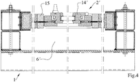
- FIG. 4 From the FIG. 4 is a horizontal section through an alternative pressure chamber 6 'according to the present invention, which only differs from the pressure chamber 6 according to Figure 1, that it is to be tested component 2' to a wooden window 14 'with a surrounding masonry 15 and Connecting means between the wooden window 14 'and the masonry 15 acts.
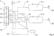
- FIG. 5 a pneumatic circuit diagram of a test setup, for example, with a pressure chamber according to FIG. 1 , wherein the connecting lines 16 of the pressure chamber 6 to one or two pressure vessels 17-1, 17-2 are shown schematically.
- a supply line 18 leads in each case via three connecting lines 16 into the pressure chamber 6, wherein all 6 connecting lines are each equipped with a shut-off element 19.
- the two supply lines are each equipped with a shut-off, so that the requirements for the accuracy of simultaneous operation of the present in the connecting lines 16 shut-off elements 19 can be reduced, however, a single larger and therefore more expensive shut-off must be used ,
- the pressure vessels 17-1, 17-2 are each supplied with compressed air by a compressor 20 (or alternatively by a single common compressor), wherein the shut-off elements 19 remain in a blocking position until a sufficient pressure in one or both pressure vessels 17- 1, 17-2 is reached.
- a compressor 20 or alternatively by a single common compressor
- the shut-off elements 19 remain in a blocking position until a sufficient pressure in one or both pressure vessels 17- 1, 17-2 is reached.
- either the compressed air of a pressure vessel 17-1 or 17-2 can be used, or at the same time the compressed air of the two pressure vessels 17-1, 17-2.
- An alternative test of the component 2 may also provide that the component 2 is first subjected to the compressed air of a pressure vessel 17-1 and after a discharge of the pressure chamber 6 via a relief valve 21 with the compressed air of the second pressure vessel 17-2, to a second time offset impinging pressure wave to simulate.
- shut-off elements 19 and the relief valve via a control device 22 which can be operated or programmed via a computer 23.
- the latter is equipped with at least one pressure sensor 24 whose recorded data is detected by the control unit 22 for control purposes.
- the control times for various test procedures can be stored, which may differ with respect to the maximum pressure, the pressure gradient in the swelling and decay phase, the pulse, the exposure time and the use of the pressure vessel.
Landscapes
- Physics & Mathematics (AREA)
- General Physics & Mathematics (AREA)
- Investigating Strength Of Materials By Application Of Mechanical Stress (AREA)
Claims (16)
- Procédé destiné à tester un élément de construction (2, 2') plan au niveau de la résistance à la pression d'explosion ou à l'effet d'un tremblement de terre, pour simuler des ondes de choc à faible impulsion, comportant les étapes de procédé suivantes :a) on encastre l'élément de construction (2, 2') de manière à transmettre la force, à conserver la pression dans un cadre de maintien (3),b) on monte le cadre de maintien (3) muni de l'élément de construction (2, 2') sur une paroi (5), de sorte à créer entre les branches de câble du câble de maintien (3), l'élément de construction (2, 2') et la paroi (5) une chambre de pression (6, 6') close par rapport à l'environnement, en conservant la pression,c) on remplit au moins un réservoir sous pression (17-1, 17-2) d'un fluide compressible, jusqu'à ce qu'il règne dans le réservoir sous pression (17-1, 17-2) une pression pB qui est supérieure à une pression environnante pU,d) on fait passer au moins un élément de blocage (19) d'un système de blocage d'une position de fermeture dans une position d'ouverture, ce qui a pour effet de créer une section transversale de liaison libre du réservoir sous pression (17-1 17-2) vers la chambre de pression (6, 6'),e) le passage de l'élément de blocage (19) de la position de fermeture dans la position d'ouverture s'effectue de manière non destructive et de manière réversible, le système de blocage étant placé dans au moins un conduit de liaison (16) entre la chambre de pression (6, 6') et le réservoir sous pression (17-1, 17-2),caractérisé par l'étape de procédé suivante :f) on ouvre une soupape de décharge (21) reliant la chambre de pression (6, 6') avec l'environnement, après avoir passé l'élément de blocage (19) du système de blocage dans la position de fermeture.
- Procédé selon la revendication 1, caractérisé en ce qu'on fait passer l'élément de blocage (19) de la position d'ouverture dans la position de fermeture, avant qu'une compensation de pression n'ait eu lieu entre la chambre de pression (6, 6') et le réservoir sous pression (17-1, 17-2) ou avant que la pression dans la chambre de pression (6, 6`) ne recommence à chuter.
- Procédé selon l'une quelconque des revendications 1 ou 2, caractérisé en ce que suite à un mouvement de fermeture, l'élément de blocage (19) accomplit de nouveau un mouvement d'ouverture, de préférence après avoir été précédemment passé dans la position de fermeture.
- Dispositif (1) destiné à tester un élément de construction (2, 2') plan au niveau de la résistance à la pression d'explosion ou à l'effet d'un tremblement de terre, pour simuler des ondes de choc à faible impulsion, comprenanta) un cadre de maintien (3) dans lequel l'élément de construction (2, 2') peut être fixé de manière à transmettre la force, à conserver la pression,b) une paroi (5) sur laquelle on peut monter le cadre de maintien (3) de sorte qu'entre des branches de cadre du cadre de maintien (3), l'élément de construction (2, 2') et la paroi (5) soit créée une chambre de pression (6, 6') close de manière à conserver la pression par rapport à l'environnement,c) un réservoir sous pression (17-1, 17-2) qui peut être rempli d'un milieu compressible jusqu'à une pression pB qui est supérieure à la pression environnante pU,d) au moins un conduit de liaison (16) qui mène du réservoir sous pression (17-1, 17-2) vers la chambre de pression (6, 6') ete) un système de blocage comportant un élément de blocage (19), qui dans une position de fermeture de l'élément de blocage (19) sépare l'un de l'autre le réservoir sous pression (17-1, 17-2) et la chambre de pression (6, 6') au niveau de la pression et dans une position d'ouverture de l'élément de blocage (19), libère une section transversale de liaison,f) l'élément de blocage (19) peut être amené de manière non destructive de la position de fermeture dans la position d'ouverture et inversement et le système de blocage est placé dans l'au moins un conduit de liaison (16),caractérisé en ce queg) le chambre de pression (6, 6') dispose d'une soupape de décharge (21) reliant avec l'environnement, qui est conçue pour relâcher en partie ou totalement la pression dans la chambre de pression (6, 6') après que l'élément de blocage (19) du système de blocage ait été passé dans la position de fermeture.
- Dispositif selon la revendication 4, caractérisé en ce que le système de blocage est une robinetterie pneumatique, notamment un robinet à boisseau sphérique.
- Dispositif selon la revendication 4 ou 5, caractérisé par un servomoteur de préférence pneumatique, à l'aide duquel le système de blocage peut être actionné.
- Dispositif selon l'une quelconque des revendications 4 à 6, caractérisé en ce que le conduit de liaison (16) est formé au moins par tronçons par un flexible.
- Dispositif selon l'une quelconque des revendications 4 à 7, caractérisé en ce que plusieurs conduits de liaison (16) montés en parallèle les uns par rapport aux autres sont munis chacun d'un système de blocage.
- Dispositif selon l'une quelconque des revendications 4 à 7, caractérisé en ce que plusieurs conduits de liaison (16) montés en parallèle et débouchant chacun dans la chambre de pression (6, 6') sont reliés par un conduit d'alimentation (18) commun, partant du réservoir sous pression, dans lequel est placé le système de blocage.
- Dispositif selon l'une quelconque des revendications 4 à 9, caractérisé en ce que des sections transversales d'embouchure présentent respectivement un écart mutuel qui s'élève à au moins 15 %, de préférence au moins 20 % d'une taille maximale de la chambre de pression.
- Dispositif selon l'une quelconque des revendications 4 à 10, caractérisé en ce qu'une profondeur (T) mesurée à la perpendiculaire de la paroi (5) de la chambre de pression (6, 6') s'élève à au moins 10 mm, de préférence à au moins 30 mm, de manière encore plus préférée à au moins 60 mm, de manière encore plus préférée à au moins 120 mm par m2 de surface d'une surface de la chambre de pression orientée à la parallèle de la paroi (5).
- Dispositif selon l'une quelconque des revendications 4 à 11, caractérisé en ce que la section transversale du conduit de liaison (16) ou la somme des sections transversales des conduits de liaison (16) est inférieure à 20 %, de préférence inférieure à 15 %, de manière plus préférée, inférieure à 10 %, de manière encore plus préférée, inférieure à 5 %, de manière vraiment plus préférée, inférieure à 3 % d'une surface de la chambre de pression (6, 6') qui est orientée à la parallèle de la paroi (5).
- Dispositif selon l'une quelconque des revendications 4 à 12, caractérisé en ce que la paroi (5) est composée d'une plaque faisant face à la chambre de pression (6, 6') et de profilés (10) renforçant cette dernière sur le côté opposé à la chambre de pression (6, 6') et reliés avec la plaque, qui présentent un dégagement mutuel d'un maximum de 200 mm, de préférence d'un maximum de 100 mm.
- Dispositif selon l'une quelconque des revendications 4 à 13, caractérisé en ce que les branches de cadre du cadre de maintien (3) sont composées d'un profilé de base conçu en un profilé rectangulaire, en forme de U, ou de double T et d'un profilé de serrage placé sur le côté opposé à la chambre de pression (6, 6'), conçu de préférence en tant que profilé plat (9), le profilé de serrage débordant de préférence du profilé de base dans la direction d'un orifice défini par le cadre de maintien (3) et soutenant l'élément de construction (2).
- Dispositif selon l'une quelconque des revendications 4 à 14, caractérisé en ce que deux réservoirs sous pression (17-1, 17-2) qui par l'intermédiaire de chaque fois un système de blocage associé sont destinés à servir soit simultanément ou de manière décalée dans le temps à appliquer une pression sur la chambre de pression (6, 6').
- Dispositif selon l'une quelconque des revendications 4 à 15, caractérisé en ce que le longueur de l'au moins un conduit de liaison (16) est comprise entre 1 m et 10 m, de préférence entre 2 m et 5 m.
Priority Applications (3)
| Application Number | Priority Date | Filing Date | Title |
|---|---|---|---|
| DK12161734.4T DK2645076T3 (en) | 2012-03-28 | 2012-03-28 | Method and apparatus for testing a flat structural element with respect to pressure |
| ES12161734.4T ES2622884T3 (es) | 2012-03-28 | 2012-03-28 | Procedimiento y dispositivo para el ensayo de un elemento de construcción plano en cuanto a la resistencia a la acción de presión |
| EP12161734.4A EP2645076B1 (fr) | 2012-03-28 | 2012-03-28 | Procédé et dispositif de test d'un élément de construction plat relatif à la résistance à la pression |
Applications Claiming Priority (1)
| Application Number | Priority Date | Filing Date | Title |
|---|---|---|---|
| EP12161734.4A EP2645076B1 (fr) | 2012-03-28 | 2012-03-28 | Procédé et dispositif de test d'un élément de construction plat relatif à la résistance à la pression |
Publications (2)
| Publication Number | Publication Date |
|---|---|
| EP2645076A1 EP2645076A1 (fr) | 2013-10-02 |
| EP2645076B1 true EP2645076B1 (fr) | 2017-02-08 |
Family
ID=45954426
Family Applications (1)
| Application Number | Title | Priority Date | Filing Date |
|---|---|---|---|
| EP12161734.4A Active EP2645076B1 (fr) | 2012-03-28 | 2012-03-28 | Procédé et dispositif de test d'un élément de construction plat relatif à la résistance à la pression |
Country Status (3)
| Country | Link |
|---|---|
| EP (1) | EP2645076B1 (fr) |
| DK (1) | DK2645076T3 (fr) |
| ES (1) | ES2622884T3 (fr) |
Families Citing this family (6)
| Publication number | Priority date | Publication date | Assignee | Title |
|---|---|---|---|---|
| DE202013012235U1 (de) | 2013-08-21 | 2015-09-28 | Sälzer GmbH | Vorrichtung zum Testen eines flächigen Bauelements bezüglich Beständigkeit gegenüber Druckeinwirkung |
| EP2840377B1 (fr) * | 2013-08-21 | 2016-09-21 | Sälzer GmbH | Procédé et dispositif de test d'un élément de construction plat relatif à la résistance à la pression |
| CZ307770B6 (cs) * | 2016-12-15 | 2019-04-24 | Vysoká Škola Báňská - Technická Univerzita Ostrava | Zkušební zařízení pro diagnostiku netěsností prostupů stavebními konstrukcemi a způsob diagnostiky netěsností prostupů stavebními konstrukcemi pomocí tohoto zařízení |
| CN111076885B (zh) * | 2019-12-31 | 2025-04-18 | 中科振声(苏州)电子科技有限公司 | 一种横摇模拟平台、测试平台和测试系统 |
| DE102021131022B4 (de) | 2021-11-25 | 2023-08-03 | Bernhard Jäger Betonwerk GmbH & Co. KG | Verfahren und Vorrichtung zum Nachweis einer wasserdichten Verbindung zwischen einem Lichtschacht und einem Bauwerk |
| CN114720064B (zh) * | 2022-03-15 | 2025-01-28 | 安徽省屯溪高压阀门股份有限公司 | 一种阀门耐压检测方法 |
Citations (5)
| Publication number | Priority date | Publication date | Assignee | Title |
|---|---|---|---|---|
| US2659235A (en) * | 1952-02-16 | 1953-11-17 | Janke And Company | Explosive atmosphere test chamber |
| US3248924A (en) * | 1961-11-22 | 1966-05-03 | William W Boynton | System for dynamic loading |
| US4967602A (en) * | 1989-05-03 | 1990-11-06 | Measurex Corporation | Pneumatic strength tester for sheet materials |
| US5197323A (en) * | 1990-07-13 | 1993-03-30 | Sparta, Inc. | Pebble-bed heater and shock tube assembly |
| WO2011104126A1 (fr) * | 2010-02-23 | 2011-09-01 | Antonio Fidelibus | Chambre d'essai pour produits résistants à l'explosion |
Family Cites Families (3)
| Publication number | Priority date | Publication date | Assignee | Title |
|---|---|---|---|---|
| DD151810A1 (de) * | 1980-07-01 | 1981-11-04 | Rainer Schulz | Pruefstand fuer fenster und tueren |
| DE3516908C1 (de) * | 1985-05-10 | 1986-05-07 | Fa. Theodor Rüschoff, 4401 Sendenhorst | Fensterprüfstand |
| DE4107093C2 (de) * | 1990-03-19 | 1994-02-03 | Volkswagen Ag | Vorrichtung zur Rißprüfung eines Formteils in einer Preßvorrichtung |
-
2012
- 2012-03-28 ES ES12161734.4T patent/ES2622884T3/es active Active
- 2012-03-28 DK DK12161734.4T patent/DK2645076T3/en active
- 2012-03-28 EP EP12161734.4A patent/EP2645076B1/fr active Active
Patent Citations (5)
| Publication number | Priority date | Publication date | Assignee | Title |
|---|---|---|---|---|
| US2659235A (en) * | 1952-02-16 | 1953-11-17 | Janke And Company | Explosive atmosphere test chamber |
| US3248924A (en) * | 1961-11-22 | 1966-05-03 | William W Boynton | System for dynamic loading |
| US4967602A (en) * | 1989-05-03 | 1990-11-06 | Measurex Corporation | Pneumatic strength tester for sheet materials |
| US5197323A (en) * | 1990-07-13 | 1993-03-30 | Sparta, Inc. | Pebble-bed heater and shock tube assembly |
| WO2011104126A1 (fr) * | 2010-02-23 | 2011-09-01 | Antonio Fidelibus | Chambre d'essai pour produits résistants à l'explosion |
Also Published As
| Publication number | Publication date |
|---|---|
| EP2645076A1 (fr) | 2013-10-02 |
| ES2622884T3 (es) | 2017-07-07 |
| DK2645076T3 (en) | 2017-04-24 |
Similar Documents
| Publication | Publication Date | Title |
|---|---|---|
| DE202012013273U1 (de) | Vorrichtung zum Testen eines flächigen Bauelements bezüglich Beständigkeit gegenüber Druckeinwirkung | |
| EP2645076B1 (fr) | Procédé et dispositif de test d'un élément de construction plat relatif à la résistance à la pression | |
| EP3534145A1 (fr) | Banc d'essai de joints d'étanchéité | |
| EP2840377B1 (fr) | Procédé et dispositif de test d'un élément de construction plat relatif à la résistance à la pression | |
| DE202007003616U1 (de) | Schaumglasplatte zur Isolierung von Gebäudefassaden | |
| DE202013012235U1 (de) | Vorrichtung zum Testen eines flächigen Bauelements bezüglich Beständigkeit gegenüber Druckeinwirkung | |
| DE10354680B4 (de) | Verfahren zum Verbinden von sich zumindest teilweise überlappenden Bauteilen | |
| DE202012104425U1 (de) | Einbauelement für eine Brandschutzklappe sowie Brandschutzklappe mit einem Einbauelement | |
| EP3626890B1 (fr) | Procédé d'essai de portance d'une fondation | |
| DD283032A7 (de) | Anordnung zur nichtmechanischen zerstoerung von beton/stahlbeton und gesteinen | |
| EP2759657A1 (fr) | Banc d'essai pour portes, fenêtres et façades | |
| DE2914467A1 (de) | Stahlglas-feuerschutztuer | |
| CH706301B1 (de) | Verfahren zur Herstellung einer Anlage zur Extraktion von Wärme aus einer Gesteinsformation. | |
| DE202011004458U1 (de) | Schallschutzsystem | |
| DE3102865A1 (de) | "sicherheits-absperrvorrichtung fuer haus-gasanschluesse" | |
| DE3140043A1 (de) | Brandschutzklappe | |
| DE102011017606A1 (de) | Ankervorrichtung zum Befestigen einer Platte an einer tragenden Grundstruktur | |
| DE202013105729U1 (de) | Befestigungsvorrichtung zum Überbrücken einer nicht tragenden Wandschicht | |
| DE102015102444B4 (de) | Verfahren und Vorrichtung zur Bestimmung der Schwenkstellung einer Vorpfändkappe | |
| EP1959073A1 (fr) | Composant léger destiné à la construction d'un renforcement de mur à partir d'objets existants, ainsi que renforcement de mur en composants légers | |
| DE2158627C2 (de) | Vorrichtung zur druck und zug festen Verankerung von vorgehängten Fas sadenplatten | |
| DE102010027368A1 (de) | Vorrichtung zur Eckbefestigung einer Leibungsplatte | |
| DE102008053638A1 (de) | Vorrichtung zum Justieren eines Bauelementes in einem Abstand zum Bauteil | |
| DE202017103088U1 (de) | Fensterschutzanordnung zum Anbringen der Fensterschutzanordnung | |
| DE102015000196A1 (de) | Schallreduktionsvorrichtung sowie ein Fügeverfahren und ein Bauteilbearbeitungsverfahren mit Schalldämmung |
Legal Events
| Date | Code | Title | Description |
|---|---|---|---|
| REG | Reference to a national code |
Ref country code: DE Ref legal event code: R138 Ref document number: 202012013273 Country of ref document: DE Free format text: GERMAN DOCUMENT NUMBER IS 502012009488 |
|
| PUAI | Public reference made under article 153(3) epc to a published international application that has entered the european phase |
Free format text: ORIGINAL CODE: 0009012 |
|
| 17P | Request for examination filed |
Effective date: 20130221 |
|
| AK | Designated contracting states |
Kind code of ref document: A1 Designated state(s): AL AT BE BG CH CY CZ DE DK EE ES FI FR GB GR HR HU IE IS IT LI LT LU LV MC MK MT NL NO PL PT RO RS SE SI SK SM TR |
|
| AX | Request for extension of the european patent |
Extension state: BA ME |
|
| RAP1 | Party data changed (applicant data changed or rights of an application transferred) |
Owner name: SAELZER GMBH |
|
| RBV | Designated contracting states (corrected) |
Designated state(s): AL AT BE BG CH CY CZ DE DK EE ES FI FR GB GR HR HU IE IS IT LI LT LU LV MC MK MT NL NO PL PT RO RS SE SI SK SM TR |
|
| 17Q | First examination report despatched |
Effective date: 20140305 |
|
| REG | Reference to a national code |
Ref country code: DE Ref legal event code: R079 Ref document number: 502012009488 Country of ref document: DE Free format text: PREVIOUS MAIN CLASS: G01M0003260000 Ipc: G01M0007080000 |
|
| TPAC | Observations filed by third parties |
Free format text: ORIGINAL CODE: EPIDOSNTIPA |
|
| GRAP | Despatch of communication of intention to grant a patent |
Free format text: ORIGINAL CODE: EPIDOSNIGR1 |
|
| RIC1 | Information provided on ipc code assigned before grant |
Ipc: G01M 3/26 20060101ALI20160520BHEP Ipc: G01M 7/08 20060101AFI20160520BHEP |
|
| INTG | Intention to grant announced |
Effective date: 20160608 |
|
| STAA | Information on the status of an ep patent application or granted ep patent |
Free format text: STATUS: GRANT OF PATENT IS INTENDED |
|
| GRAS | Grant fee paid |
Free format text: ORIGINAL CODE: EPIDOSNIGR3 |
|
| GRAA | (expected) grant |
Free format text: ORIGINAL CODE: 0009210 |
|
| STAA | Information on the status of an ep patent application or granted ep patent |
Free format text: STATUS: THE PATENT HAS BEEN GRANTED |
|
| AK | Designated contracting states |
Kind code of ref document: B1 Designated state(s): AL AT BE BG CH CY CZ DE DK EE ES FI FR GB GR HR HU IE IS IT LI LT LU LV MC MK MT NL NO PL PT RO RS SE SI SK SM TR |
|
| REG | Reference to a national code |
Ref country code: GB Ref legal event code: FG4D Free format text: NOT ENGLISH |
|
| REG | Reference to a national code |
Ref country code: CH Ref legal event code: EP Ref country code: AT Ref legal event code: REF Ref document number: 867087 Country of ref document: AT Kind code of ref document: T Effective date: 20170215 |
|
| REG | Reference to a national code |
Ref country code: IE Ref legal event code: FG4D Free format text: LANGUAGE OF EP DOCUMENT: GERMAN |
|
| REG | Reference to a national code |
Ref country code: DE Ref legal event code: R096 Ref document number: 502012009488 Country of ref document: DE |
|
| REG | Reference to a national code |
Ref country code: FR Ref legal event code: PLFP Year of fee payment: 6 |
|
| REG | Reference to a national code |
Ref country code: DK Ref legal event code: T3 Effective date: 20170420 |
|
| REG | Reference to a national code |
Ref country code: NL Ref legal event code: FP |
|
| REG | Reference to a national code |
Ref country code: NO Ref legal event code: T2 Effective date: 20170208 |
|
| REG | Reference to a national code |
Ref country code: LT Ref legal event code: MG4D |
|
| REG | Reference to a national code |
Ref country code: ES Ref legal event code: FG2A Ref document number: 2622884 Country of ref document: ES Kind code of ref document: T3 Effective date: 20170707 |
|
| PG25 | Lapsed in a contracting state [announced via postgrant information from national office to epo] |
Ref country code: LT Free format text: LAPSE BECAUSE OF FAILURE TO SUBMIT A TRANSLATION OF THE DESCRIPTION OR TO PAY THE FEE WITHIN THE PRESCRIBED TIME-LIMIT Effective date: 20170208 Ref country code: HR Free format text: LAPSE BECAUSE OF FAILURE TO SUBMIT A TRANSLATION OF THE DESCRIPTION OR TO PAY THE FEE WITHIN THE PRESCRIBED TIME-LIMIT Effective date: 20170208 Ref country code: FI Free format text: LAPSE BECAUSE OF FAILURE TO SUBMIT A TRANSLATION OF THE DESCRIPTION OR TO PAY THE FEE WITHIN THE PRESCRIBED TIME-LIMIT Effective date: 20170208 |
|
| PG25 | Lapsed in a contracting state [announced via postgrant information from national office to epo] |
Ref country code: SE Free format text: LAPSE BECAUSE OF FAILURE TO SUBMIT A TRANSLATION OF THE DESCRIPTION OR TO PAY THE FEE WITHIN THE PRESCRIBED TIME-LIMIT Effective date: 20170208 Ref country code: RS Free format text: LAPSE BECAUSE OF FAILURE TO SUBMIT A TRANSLATION OF THE DESCRIPTION OR TO PAY THE FEE WITHIN THE PRESCRIBED TIME-LIMIT Effective date: 20170208 Ref country code: PT Free format text: LAPSE BECAUSE OF FAILURE TO SUBMIT A TRANSLATION OF THE DESCRIPTION OR TO PAY THE FEE WITHIN THE PRESCRIBED TIME-LIMIT Effective date: 20170608 Ref country code: BG Free format text: LAPSE BECAUSE OF FAILURE TO SUBMIT A TRANSLATION OF THE DESCRIPTION OR TO PAY THE FEE WITHIN THE PRESCRIBED TIME-LIMIT Effective date: 20170508 Ref country code: LV Free format text: LAPSE BECAUSE OF FAILURE TO SUBMIT A TRANSLATION OF THE DESCRIPTION OR TO PAY THE FEE WITHIN THE PRESCRIBED TIME-LIMIT Effective date: 20170208 |
|
| REG | Reference to a national code |
Ref country code: GR Ref legal event code: EP Ref document number: 20170401111 Country of ref document: GR Effective date: 20170831 |
|
| PG25 | Lapsed in a contracting state [announced via postgrant information from national office to epo] |
Ref country code: CZ Free format text: LAPSE BECAUSE OF FAILURE TO SUBMIT A TRANSLATION OF THE DESCRIPTION OR TO PAY THE FEE WITHIN THE PRESCRIBED TIME-LIMIT Effective date: 20170208 Ref country code: EE Free format text: LAPSE BECAUSE OF FAILURE TO SUBMIT A TRANSLATION OF THE DESCRIPTION OR TO PAY THE FEE WITHIN THE PRESCRIBED TIME-LIMIT Effective date: 20170208 Ref country code: RO Free format text: LAPSE BECAUSE OF FAILURE TO SUBMIT A TRANSLATION OF THE DESCRIPTION OR TO PAY THE FEE WITHIN THE PRESCRIBED TIME-LIMIT Effective date: 20170208 Ref country code: SK Free format text: LAPSE BECAUSE OF FAILURE TO SUBMIT A TRANSLATION OF THE DESCRIPTION OR TO PAY THE FEE WITHIN THE PRESCRIBED TIME-LIMIT Effective date: 20170208 |
|
| REG | Reference to a national code |
Ref country code: DE Ref legal event code: R097 Ref document number: 502012009488 Country of ref document: DE |
|
| PG25 | Lapsed in a contracting state [announced via postgrant information from national office to epo] |
Ref country code: PL Free format text: LAPSE BECAUSE OF FAILURE TO SUBMIT A TRANSLATION OF THE DESCRIPTION OR TO PAY THE FEE WITHIN THE PRESCRIBED TIME-LIMIT Effective date: 20170208 Ref country code: SM Free format text: LAPSE BECAUSE OF FAILURE TO SUBMIT A TRANSLATION OF THE DESCRIPTION OR TO PAY THE FEE WITHIN THE PRESCRIBED TIME-LIMIT Effective date: 20170208 Ref country code: MC Free format text: LAPSE BECAUSE OF FAILURE TO SUBMIT A TRANSLATION OF THE DESCRIPTION OR TO PAY THE FEE WITHIN THE PRESCRIBED TIME-LIMIT Effective date: 20170208 |
|
| PLBE | No opposition filed within time limit |
Free format text: ORIGINAL CODE: 0009261 |
|
| STAA | Information on the status of an ep patent application or granted ep patent |
Free format text: STATUS: NO OPPOSITION FILED WITHIN TIME LIMIT |
|
| 26N | No opposition filed |
Effective date: 20171109 |
|
| PG25 | Lapsed in a contracting state [announced via postgrant information from national office to epo] |
Ref country code: SI Free format text: LAPSE BECAUSE OF FAILURE TO SUBMIT A TRANSLATION OF THE DESCRIPTION OR TO PAY THE FEE WITHIN THE PRESCRIBED TIME-LIMIT Effective date: 20170208 |
|
| REG | Reference to a national code |
Ref country code: FR Ref legal event code: PLFP Year of fee payment: 7 |
|
| PG25 | Lapsed in a contracting state [announced via postgrant information from national office to epo] |
Ref country code: MT Free format text: LAPSE BECAUSE OF FAILURE TO SUBMIT A TRANSLATION OF THE DESCRIPTION OR TO PAY THE FEE WITHIN THE PRESCRIBED TIME-LIMIT Effective date: 20170208 |
|
| PG25 | Lapsed in a contracting state [announced via postgrant information from national office to epo] |
Ref country code: HU Free format text: LAPSE BECAUSE OF FAILURE TO SUBMIT A TRANSLATION OF THE DESCRIPTION OR TO PAY THE FEE WITHIN THE PRESCRIBED TIME-LIMIT; INVALID AB INITIO Effective date: 20120328 |
|
| PG25 | Lapsed in a contracting state [announced via postgrant information from national office to epo] |
Ref country code: CY Free format text: LAPSE BECAUSE OF NON-PAYMENT OF DUE FEES Effective date: 20170208 |
|
| PG25 | Lapsed in a contracting state [announced via postgrant information from national office to epo] |
Ref country code: MK Free format text: LAPSE BECAUSE OF FAILURE TO SUBMIT A TRANSLATION OF THE DESCRIPTION OR TO PAY THE FEE WITHIN THE PRESCRIBED TIME-LIMIT Effective date: 20170208 |
|
| PG25 | Lapsed in a contracting state [announced via postgrant information from national office to epo] |
Ref country code: AL Free format text: LAPSE BECAUSE OF FAILURE TO SUBMIT A TRANSLATION OF THE DESCRIPTION OR TO PAY THE FEE WITHIN THE PRESCRIBED TIME-LIMIT Effective date: 20170208 Ref country code: IS Free format text: LAPSE BECAUSE OF FAILURE TO SUBMIT A TRANSLATION OF THE DESCRIPTION OR TO PAY THE FEE WITHIN THE PRESCRIBED TIME-LIMIT Effective date: 20170608 |
|
| REG | Reference to a national code |
Ref country code: DE Ref legal event code: R082 Ref document number: 502012009488 Country of ref document: DE Representative=s name: PATENT- UND RECHTSANWAELTE LOESENBECK, SPECHT,, DE Ref country code: DE Ref legal event code: R082 Ref document number: 502012009488 Country of ref document: DE Representative=s name: BAUER WAGNER PELLENGAHR SROKA PATENT- & RECHTS, DE |
|
| PGFP | Annual fee paid to national office [announced via postgrant information from national office to epo] |
Ref country code: IE Payment date: 20220321 Year of fee payment: 11 Ref country code: DK Payment date: 20220324 Year of fee payment: 11 Ref country code: CH Payment date: 20220324 Year of fee payment: 11 Ref country code: AT Payment date: 20220318 Year of fee payment: 11 |
|
| PGFP | Annual fee paid to national office [announced via postgrant information from national office to epo] |
Ref country code: TR Payment date: 20220308 Year of fee payment: 11 Ref country code: NO Payment date: 20220322 Year of fee payment: 11 Ref country code: NL Payment date: 20220325 Year of fee payment: 11 Ref country code: LU Payment date: 20220325 Year of fee payment: 11 Ref country code: IT Payment date: 20220322 Year of fee payment: 11 Ref country code: GR Payment date: 20220321 Year of fee payment: 11 Ref country code: FR Payment date: 20220325 Year of fee payment: 11 |
|
| PGFP | Annual fee paid to national office [announced via postgrant information from national office to epo] |
Ref country code: ES Payment date: 20220418 Year of fee payment: 11 |
|
| REG | Reference to a national code |
Ref country code: DE Ref legal event code: R082 Ref document number: 502012009488 Country of ref document: DE Representative=s name: PATENT- UND RECHTSANWAELTE LOESENBECK, SPECHT,, DE |
|
| P01 | Opt-out of the competence of the unified patent court (upc) registered |
Effective date: 20230818 |
|
| REG | Reference to a national code |
Ref country code: NO Ref legal event code: MMEP |
|
| REG | Reference to a national code |
Ref country code: CH Ref legal event code: PL |
|
| REG | Reference to a national code |
Ref country code: DK Ref legal event code: EBP Effective date: 20230331 |
|
| REG | Reference to a national code |
Ref country code: NL Ref legal event code: MM Effective date: 20230401 |
|
| REG | Reference to a national code |
Ref country code: AT Ref legal event code: MM01 Ref document number: 867087 Country of ref document: AT Kind code of ref document: T Effective date: 20230328 |
|
| PG25 | Lapsed in a contracting state [announced via postgrant information from national office to epo] |
Ref country code: NL Free format text: LAPSE BECAUSE OF NON-PAYMENT OF DUE FEES Effective date: 20230401 Ref country code: LU Free format text: LAPSE BECAUSE OF NON-PAYMENT OF DUE FEES Effective date: 20230328 |
|
| REG | Reference to a national code |
Ref country code: IE Ref legal event code: MM4A |
|
| PG25 | Lapsed in a contracting state [announced via postgrant information from national office to epo] |
Ref country code: GR Free format text: LAPSE BECAUSE OF NON-PAYMENT OF DUE FEES Effective date: 20231009 |
|
| PG25 | Lapsed in a contracting state [announced via postgrant information from national office to epo] |
Ref country code: NO Free format text: LAPSE BECAUSE OF NON-PAYMENT OF DUE FEES Effective date: 20230331 Ref country code: LI Free format text: LAPSE BECAUSE OF NON-PAYMENT OF DUE FEES Effective date: 20230331 Ref country code: IE Free format text: LAPSE BECAUSE OF NON-PAYMENT OF DUE FEES Effective date: 20230328 Ref country code: GR Free format text: LAPSE BECAUSE OF NON-PAYMENT OF DUE FEES Effective date: 20231009 Ref country code: FR Free format text: LAPSE BECAUSE OF NON-PAYMENT OF DUE FEES Effective date: 20230331 Ref country code: CH Free format text: LAPSE BECAUSE OF NON-PAYMENT OF DUE FEES Effective date: 20230331 Ref country code: AT Free format text: LAPSE BECAUSE OF NON-PAYMENT OF DUE FEES Effective date: 20230328 |
|
| PG25 | Lapsed in a contracting state [announced via postgrant information from national office to epo] |
Ref country code: IT Free format text: LAPSE BECAUSE OF NON-PAYMENT OF DUE FEES Effective date: 20230328 Ref country code: DK Free format text: LAPSE BECAUSE OF NON-PAYMENT OF DUE FEES Effective date: 20230331 |
|
| REG | Reference to a national code |
Ref country code: ES Ref legal event code: FD2A Effective date: 20240527 |
|
| PG25 | Lapsed in a contracting state [announced via postgrant information from national office to epo] |
Ref country code: ES Free format text: LAPSE BECAUSE OF NON-PAYMENT OF DUE FEES Effective date: 20230329 |
|
| PG25 | Lapsed in a contracting state [announced via postgrant information from national office to epo] |
Ref country code: ES Free format text: LAPSE BECAUSE OF NON-PAYMENT OF DUE FEES Effective date: 20230329 |
|
| PGFP | Annual fee paid to national office [announced via postgrant information from national office to epo] |
Ref country code: GB Payment date: 20260305 Year of fee payment: 15 |
|
| PGFP | Annual fee paid to national office [announced via postgrant information from national office to epo] |
Ref country code: DE Payment date: 20260305 Year of fee payment: 15 |
|
| PGFP | Annual fee paid to national office [announced via postgrant information from national office to epo] |
Ref country code: BE Payment date: 20260306 Year of fee payment: 15 |