EP2645181A2 - Appareil de formation d'images - Google Patents
Appareil de formation d'images Download PDFInfo
- Publication number
- EP2645181A2 EP2645181A2 EP13159590.2A EP13159590A EP2645181A2 EP 2645181 A2 EP2645181 A2 EP 2645181A2 EP 13159590 A EP13159590 A EP 13159590A EP 2645181 A2 EP2645181 A2 EP 2645181A2
- Authority
- EP
- European Patent Office
- Prior art keywords
- process cartridge
- guide
- casing
- image forming
- forming apparatus
- Prior art date
- Legal status (The legal status is an assumption and is not a legal conclusion. Google has not performed a legal analysis and makes no representation as to the accuracy of the status listed.)
- Granted
Links
Images


Classifications
-
- G—PHYSICS
- G03—PHOTOGRAPHY; CINEMATOGRAPHY; ANALOGOUS TECHNIQUES USING WAVES OTHER THAN OPTICAL WAVES; ELECTROGRAPHY; HOLOGRAPHY
- G03G—ELECTROGRAPHY; ELECTROPHOTOGRAPHY; MAGNETOGRAPHY
- G03G21/00—Arrangements not provided for by groups G03G13/00 - G03G19/00, e.g. cleaning, elimination of residual charge
- G03G21/16—Mechanical means for facilitating the maintenance of the apparatus, e.g. modular arrangements
- G03G21/18—Mechanical means for facilitating the maintenance of the apparatus, e.g. modular arrangements using a processing cartridge, whereby the process cartridge comprises at least two image processing means in a single unit
- G03G21/1839—Means for handling the process cartridge in the apparatus body
- G03G21/1842—Means for handling the process cartridge in the apparatus body for guiding and mounting the process cartridge, positioning, alignment, locks
-
- G—PHYSICS
- G03—PHOTOGRAPHY; CINEMATOGRAPHY; ANALOGOUS TECHNIQUES USING WAVES OTHER THAN OPTICAL WAVES; ELECTROGRAPHY; HOLOGRAPHY
- G03G—ELECTROGRAPHY; ELECTROPHOTOGRAPHY; MAGNETOGRAPHY
- G03G21/00—Arrangements not provided for by groups G03G13/00 - G03G19/00, e.g. cleaning, elimination of residual charge
- G03G21/16—Mechanical means for facilitating the maintenance of the apparatus, e.g. modular arrangements
- G03G21/1604—Arrangement or disposition of the entire apparatus
- G03G21/1623—Means to access the interior of the apparatus
- G03G21/1633—Means to access the interior of the apparatus using doors or covers
-
- G—PHYSICS
- G03—PHOTOGRAPHY; CINEMATOGRAPHY; ANALOGOUS TECHNIQUES USING WAVES OTHER THAN OPTICAL WAVES; ELECTROGRAPHY; HOLOGRAPHY
- G03G—ELECTROGRAPHY; ELECTROPHOTOGRAPHY; MAGNETOGRAPHY
- G03G21/00—Arrangements not provided for by groups G03G13/00 - G03G19/00, e.g. cleaning, elimination of residual charge
- G03G21/16—Mechanical means for facilitating the maintenance of the apparatus, e.g. modular arrangements
- G03G21/18—Mechanical means for facilitating the maintenance of the apparatus, e.g. modular arrangements using a processing cartridge, whereby the process cartridge comprises at least two image processing means in a single unit
- G03G21/1839—Means for handling the process cartridge in the apparatus body
- G03G21/1842—Means for handling the process cartridge in the apparatus body for guiding and mounting the process cartridge, positioning, alignment, locks
- G03G21/1853—Means for handling the process cartridge in the apparatus body for guiding and mounting the process cartridge, positioning, alignment, locks the process cartridge being mounted perpendicular to the axis of the photosensitive member
Definitions
- aspects of the disclosure relate to an image forming apparatus including a casing and a process cartridge detachably attachable to the casing.
- a known image forming apparatus includes a process cartridge detachably attachable to a main body of the image forming apparatus by being guided by a guide provided in the main body, as disclosed in, for example, Japanese Laid-Open Patent Publication No. 2011-227457 .
- the main body includes a casing having an opening that is open upward and a cover to open and close the opening.
- the guide is formed in the casing and extends diagonally from the opening to a rear side of the casing.
- the cover includes a pressing portion configured to press the process cartridge being attached toward an attachment position when the cover closes the opening.
- the pressing portion is configured to contact a horizontal surface of the process cartridge and press the horizontal surface vertically.
- a direction in which the guide extends is different from a direction in which the pressing portion presses the process cartridge, and thus the user needs to press the cover strongly when closing it.
- Illustrative aspects of the disclosure provide an image forming apparatus configured such that a cover is closed lightly while a process cartridge is moved to its attachment position.
- an image forming apparatus includes a casing having an opening that is open upward, a cover supported by the casing, a process cartridge configured to be attached to or removed from the casing through the opening, and a particular guide configured to guide the process cartridge when the process cartridge is attached to or removed from the casing.
- the cover is configured to pivot around a pivot axis to open and close the opening.
- the cover includes a pressing portion. The pressing portion is configured to, when the cover is closing the opening, contact the process cartridge being attached inside the casing and press the process cartridge toward an attachment position in which the process cartridge is attached to the casing.
- a path of the pressing portion in the casing, while the cover pivots, is substantially same as a shape of the particular guide as viewed from an axial direction of the pivot axis.
- a direction in which the process cartridge is attached agrees with a direction in which the pressing portion presses the process cartridge, and thus the cover can be closed lightly while the process cartridge can be moved to its attachment position.
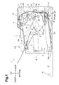
- Fig. 1 illustrates a general structure of an illustrative image forming apparatus, e.g. a laser printer, according to an embodiment of the disclosure
- Fig. 2 illustrates the laser printer with a top cover thereof being open, wherein a process cartridge is removed
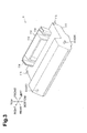
- Fig. 3 is a perspective view illustrating the process cartridge
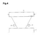
- Fig. 4 illustrates a range in which a laser beam to be emitted from a scanner unit passes and positions of pressing portions
- Fig. 5 illustrates that, when the process cartridge is attached, a shaft of a photosensitive drum is guided by a first guide
- Fig. 6 illustrates that, when the process cartridge is attached, a boss is guided by an upper portion of a second guide
- Fig. 7 illustrates that, when the process cartridge is attached, the boss is guided by a lower portion of the second guide
- Fig. 8 illustrates that the process cartridge moves further toward an attachment position than that shown in Fig. 7 ;
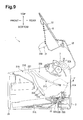
- Fig. 9 illustrates that the process cartridge is attached to the casing.
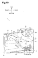
- Fig. 10 illustrates that the pressing portion contacts the process cartridge being attached.
- orientations or sides of the laser printer will be identified based on the laser printer disposed in an orientation in which it is intended to be used.
- the left side is referred to as the front or front side
- the right side is referred to as the rear or the rear side
- the up side is referred to as the top or upper side
- the down side is referred to as the bottom or lower side.
- the top and bottom direction may be referred to as a vertical direction.
- the laser printer 1 includes a main body 2, a feeder portion 3 for feeding a sheet P, and an image forming portion 4 for forming an image on the sheet P.
- the main body 2 includes a casing 21, a top cover 22 as an example of a cover, and a front cover 23.
- the casing 21 has an opening 21A ( Fig. 2 ), which is open upward, for attaching and removing a process cartridge 6 in an upper portion, and an insertion opening 21B for inserting sheets P in a front portion.
- the dimension of the opening 21A in the left-right direction is substantially equal to that of the process cartridge 6, and the dimension of the opening 21A in the front-rear direction is smaller than the dimension of the process cartridge 6 in a direction where a photosensitive drum 61 and a handle portion 113 are arranged.
- the top cover 22 is sized to cover the entire of the upper side of the casing 21 and is supported by the casing 21 such that the top cover 22 is configured to pivot about a pivot 22A disposed in a rear end portion of the casing 21. Thus, by being moved vertically, the top cover 22 is configured to open and close the opening 21A.
- An upper surface of the top cover 22 contains an ejection tray 9 on which a sheet P ejected by an ejection roller 8 outside the casing 21 is to be placed.
- the ejection tray 9 includes an extension cover 10.
- the extension cover 10 is supported by the top cover 22 such that the extension cover 10 is configured to pivot about a pivot shaft (not shown) disposed in a front end portion of the top cover 22.
- the extension cover 10 is configured to move between a position (indicated by a double dotted line) covering an upper surface of the ejection tray 9 and a position (indicated by a solid line) approximate to the ejection tray 9 supporting the leading end portion of a sheet P on the ejection tray 9.
- the front cover 23 is a cover covering a front surface of the casing 21 and is pivotally supported at its lower end portion by the casing 21. With this structure, by being pivoted in the front-rear direction, the front cover 23 is configured to open and close the insertion opening 21B of the casing 21.
- the feeder portion 3 is disposed in a lower portion of the main body 2, and includes a sheet tray 31 for placing a sheet P thereon and a sheet feed mechanism 32 that feeds a sheet P on the sheet tray 31 toward the image forming portion 4.
- the sheet tray 31 includes the front cover 23 and a sheet receiving plate 31A, which is disposed in a lower portion of the main body 2. Specifically, when tilted frontward, the front cover 23 constitutes a part of the sheet tray 31.
- the sheet receiving plate 31A is configured to raise a sheet P toward a feed roller 32A at timing when one sheet P is fed.
- the sheet feed mechanism 32 includes the feed roller 32A, a separation roller 32B, and a separation pad 32C.
- the feed roller 32A is disposed upstream of the separation roller 32B in a sheet conveying direction, and above the rear end of the sheet receiving plate 31A.
- the separation roller 32B is disposed facing the separation pad 32C.
- the front cover 23 is tilted down frontward to form the sheet tray 31, and a sheet P is placed on the sheet tray 31.
- the feed roller 32A rotates in contact with the sheet P placed on the sheet tray 31, and the sheet P placed on the sheet tray 31 is conveyed to the separation roller 32B, the fed sheet P is singly separated by the separation roller 32B and the separation pad 32C and conveyed to the image forming portion 4.
- the image forming portion 4 includes a scanner unit 5, a process cartridge 6, and a fixing unit 7.
- the scanner unit 5 is disposed above a front side of the feeder portion 3 in the main body 2, and includes a laser emitting portion, a polygon mirror, and a lens, which are not shown.
- the scanner unit 5 irradiates a surface of a photosensitive drum 61, as an example of a photosensitive member, with a laser beam at high speed scanning.
- the process cartridge 6 is disposed above a rear side of the feeder portion 3 in the main body 2, and is detachable through the opening 21A from the casing 21.
- the process cartridge 6 includes a photosensitive drum 61, a transfer roller 62 facing the photosensitive drum 61, an unnumbered charger, a developing roller 63, and a toner chamber, which is not shown.
- the surface of the photosensitive drum 61 which is rotating, is uniformly charged by the charger, and then exposed with the laser beam from the scanner unit 5 by high speed scanning. Thus, a potential in an exposed area drops, and an electrostatic latent image based on image data is formed on the surface of the photosensitive drum 61.
- the developing roller 63 supplies toner in the toner chamber to the electrostatic latent image formed on the photosensitive drum 61, and a toner image is formed on the surface of the photosensitive drum 61. Then, when a sheet P is fed in between the photosensitive drum 61 and the transfer roller 62, the toner image carried on the surface of the photosensitive drum 61 is transferred onto the sheet P.
- the fixing unit 7 is disposed above the process cartridge 6 in a rear side of the main body 2.
- the fixing unit 7 includes a heat roller 71 and a pressure roller 72.
- the heat roller 71 is a member that applies heat to a sheet P, and includes inside a heat source, e.g., a halogen lamp.
- the pressure roller 72 is a member that feeds a sheet P by sandwiching the sheet P with the heat roller 71, and is disposed diagonally upward from the rear side of the heat roller 71.
- the fixing unit 7 structured as described above is configured to fix toner transferred onto the sheet P thermally while the sheet P passes between the heat roller 71 and the pressure roller 72.
- the sheet P having the toner thermally fixed thereon is conveyed to the ejection roller 8, which is disposed downstream of the fixing unit 7, and ejected from the ejection roller 8 to the ejection tray 9.
- the process cartridge 6 rotatably supports, at its rear end portion, the photosensitive drum 61 and the transfer roller 62 ( Fig. 1 ).
- a front wall 112 disposed in a front end portion of the process cartridge 6 is provided with the handle portion 113 and pressed portions 114.
- Bosses 115 are disposed on the left and right side surfaces 111 of the process cartridge 6.
- the handle portion 113 is a portion held by a user during attachment or removal of the process cartridge 6, and is disposed in substantially a central portion of the process cartridge 6 in the left-right direction.
- the pressed portions 114 are portions which respective pressing portions 24 contact when the top cover 22 is closing the opening 21A.
- the pressed portions 114 are upper end surfaces of ribs protruding rearward from the front wall 112 with the handle portion 113 interposed therebetween.
- the bosses 115 are protrusions protruding outward from the left and right side surfaces 111 in the left-right direction.
- the bosses 115 are disposed in front end portions of the left and right side surfaces 111.
- the handle portion 113 is disposed closer to the bosses 115 than the shaft 61A of the photosensitive drum 61.
- the bosses 115 are disposed in upper end portions of front sides of the respective left and right side surfaces 111 and in positions where the bosses 115 overlap the pressed portions 114 in a direction where the shaft 61A and the bosses 115 are arranged and near the pressed portions 114.
- the process cartridge 6 structured as described above when attached to the casing 21, the process cartridge 6 structured as described above is disposed with its front end portion being lower than its rear end portion such that the handle portion 113 is disposed in a position lower than an exposure portion 61B of the photosensitive drum 61, which is to be exposed by the scanner unit 5.
- the scanner unit 5 is disposed in a position upper than the handle portion 113 such that laser light is not cut off by the handle portion 113.
- the scanner unit 5 is disposed in a lower position compared with a case where the handle portion 113 is disposed above the exposure portion 61B of the photosensitive drum 61, and thus the need to increase the physical size of the main body 2 can be obviated.
- the main body 2 includes a guide 200 disposed in the casing 21 and the pressing portions 24 disposed in the top cover 22 as a structure to attach and remove the process cartridge 6 with respect to the casing 21.
- the guide 200 is made up of a first guide 210 as an example of a further guide and a second guide 220 as an example of a particular guide, and is configured to guide the process cartridge 6 being attached or removed by guiding the shaft 61A of the photosensitive drum 61 by the first guide 210 and guiding the boss 115 by the second guide 220.
- the guide 200 is configured to hold the shaft 61A of the photosensitive drum 61 of the process cartridge 6 attached to the casing 21 and the boss 115 at their attachment positions ( Fig. 1 ).
- the first guide 210 is a groove formed in an inner surface of a side panel 21C disposed on each of the left and right sides of the casing 21.
- the first guide 210 is shaped to extend in an attaching direction where the process cartridge 6 is attached or diagonally downward from the opening 21A to the inside of the casing 21 such as to connect an upper end of the side panel 21C and the attachment position of the shaft 61A of the photosensitive drum 61.
- the second guide 220 is a groove formed in the inner surface of the side panel 21C of the casing 21 in front of the first guide 210.
- the second guide 220 is shaped to connect the attachment position of the boss 115 and the upper end of the side panel 21C.
- the second guide 220 has an upper portion 221 disposed on an upstream side in the attaching direction of the process cartridge 6 and a lower portion 222 disposed on a downstream side in the attaching direction of the process cartridge 6.
- the upper portion 221 extends from the upper end of the side panel 21C substantially straightly along the first guide 210.
- the lower portion 222 extends smoothly from a lower end of the upper portion 221 to the stop position of the boss 115, and is curved away from the first guide 210.
- the lower portion 222 extends in a direction crossing a direction where the upper portion 221 extends. In other words, the second guide 220 is bent at a portion where the upper portion 221 merges with the lower portion 222.
- the second guide 220 is longer in the vertical length than the first guide 210, and the lower end of the second guide 220 is located lower than the lower end of the first guide 210.
- the bent portion of the second guide 220 is disposed in a position closer to the upper end of the side panel 21C than the attachment position of the boss 115.
- the first guide 210 and the second guide 220 have such lengths that, during attaching of the process cartridge 6, the boss 115 is guided to its attachment position after the shaft 61A of the photosensitive drum 61 is guided to its attachment position.
- the pressing portions 24 are members that, when the top cover 22 closes the opening 21A, contact the pressed portions 114 of the process cartridge 6 being attached and press the process cartridge 6 into an attachment position in which the process cartridge 6 is attached to the casing 21.
- the pressing portions 24 are disposed on a surface of the top cover 22 opposite to the ejection tray 9 and protrude inside of the casing 21 from the top cover 22 when the top cover 22 closes the opening 21A. As shown in Fig. 4 , the pressing portions 24 are disposed one by one on the left and right sides to correspond the pressed portions 114 of the process cartridge 6. The pressing portions 24 are arranged such that laser light emitted from the scanner unit 5 passes between the pressing portions 24. In other words, the pressing portions 24 are disposed outside of a range where the laser light passes (or a range inside broken lines in Fig. 4 ).
- an end surface of the pressing portion 24 is a pressing surface 24A, as an example of a pressing portion, to contact the pressed portion 114 of the process cartridge 6.
- a path of the pressing surface 24A in the casing 21 while the top cover 22 is opened or closed is substantially same as the shape of the second guide 220.
- the path of the pressing surface 24A for a period of time from when the pressing surface 24A contacts the pressed portion 114 to when the process cartridge 6 moves to the attachment position is substantially same as the shape of the second guide 220 through which the boss 115 passes.
- the pressing surface 24A is shaped such as to, when contacting the pressed portion 114, face toward the attaching direction of the boss 115 such that a direction in which the pressing surface 24A presses the pressed portion 114 is substantially parallel to a direction in which the second guide 220 extends in proximity to the boss 115 ( Fig. 10 ).
- the user can close the top cover 22 while moving the process cartridge 6 to the attachment position lightly.
- the boss 115 is not pressed to the second guide 220 with a force that the pressing portion 24 presses the pressed portion 114.
- the process cartridge 6 is moved to the attachment position with a small force.
- the pressing portion 24 is disposed in such a position in the front-rear direction as to, when the pressing portion 24 contacts the pressed portion 114 of the process cartridge 6, overlap the second guide 220 in a radial direction of a circle centered on the pivot 22A (a pivot axis) of the top cover 22. In other words, the pressing portion 24 is disposed so as to overlap the second guide 220 as viewed from an axial direction of the pivot 22A.
- This positional relationship reduces the potential of the process cartridge 6 from being twisted when being pressed by the pressing portion 24, compared with a case where the pressing portion 24 is disposed in a position away from the second guide 220 in the radial direction of the circle centered on the pivot 22A of the top cover 22.
- a user opens the top cover 22, holds the handle portion 113, and brings the process cartridge 6 close to the casing 21 from the photosensitive drum 61 side. As shown in Fig. 5 , the user inserts the shaft 61A of the photosensitive drum 61 into the first guide 210 to move the process cartridge 6 into the casing 21 along the first guide 210.
- the boss 115 is inserted into the upper portion 221 of the second guide 220.
- a portion of the second guide 220 that guides the boss 115 changes from the upper portion 221 to the lower portion 222.
- the boss 115 is guide by the lower portion 222 to move toward the attachment position.
- the lower portion 222 allows the process cartridge 6 to move smoothly because the lower portion 222 has a smooth curved shape to the attachment position of the boss 115.
- the boss 115 stops at the end of the lower portion 222 of the second guide 220 so that the process cartridge 6 is attached to the casing 21 as shown in Fig. 9 .
- the pressing portion 24 contacts the pressed portion 114 of the process cartridge 6 located short of the attachment position, and presses the process cartridge 6 into the attachment position.
- the pressing portion 24 allows the process cartridge 6 to be attached in position.
- the user opens the top cover 22, holds the handle portion 113 of the process cartridge 6, and pulls the process cartridge 6 toward the user.
- the shaft 61A of the photosensitive drum 61 is guided by the first guide 210
- the boss 115 is guided by the second guide 220
- the process cartridge 6 moves outward in the casing 21.
- the lower portion 222 has a smooth curved shape from the attachment position of the boss 115 to the upper portion 221, a moving direction of the process cartridge 6 is not greatly changed in the vicinity of the attachment position of the boss 115.
- the process cartridge 6 can be pulled out smoothly.
- the attaching direction of the process cartridge 6 agrees with the direction where the pressing surface 24A presses the process cartridge 6.
- the user can close the top cover while moving the process cartridge 6 to the attachment position lightly.
- the direction where the pressing surface 24A presses the process cartridge 6 is substantially parallel to the direction where the second guide 220 extends in the vicinity of the boss 115.
- the boss 115 is not pressed against the second guide 220.
- the user can press the top cover 22 lightly to close the top cover 22.
- the pressing surface 24A When contacting the process cartridge 6, the pressing surface 24A is disposed in the position where it overlaps the second guide 220 in the radial direction of a circle centered on the pivot 22A of the top cover 22.
- the process cartridge 6 can be prevented from being twisted when being pressed by the pressing surface 24A.
- the pressed portions 114 are disposed at the upper end portion of the entire process cartridge 6, and the bosses 115 are disposed at the upper end portion of the side surfaces 111 of the process cartridge 6. Thus, the pressed portions 114 and the bosses 115 are disposed near each other.
- the moving direction of the bosses 115 is similar to the direction where the pressing surface 24A presses.
- the pressing surface 24A is disposed in the position where it overlaps the second guide 220 in the radial direction of a circle centered on the pivot 22A of the top cover 22.
- the pressing surface 24A may be disposed in a position shifted from the second guide 220 in the radial direction of a circle centered on the pivot 22A when the pressing surface 24A contacts the pressed portions 114 of the process cartridge 6.
- the above embodiment shows, but is not limited to the pressing surface 24A which is flat and formed at a distal end of the pressing portion 24.
- the pressing portion 24 may have a round distal end which is to contact the pressed portions 114 of the process cartridge 6.
- a point of the distal end of the pressing portion 24 that contacts the pressed portion 114 is a pressing portion.
- the above embodiment shows, but is not limited to, that the photosensitive drum 61 is illustrated as the photosensitive member.
- a belt-shaped photosensitive member may be used.
Landscapes
- Physics & Mathematics (AREA)
- General Physics & Mathematics (AREA)
- Engineering & Computer Science (AREA)
- Computer Vision & Pattern Recognition (AREA)
- Electrophotography Configuration And Component (AREA)
- Dry Development In Electrophotography (AREA)
Applications Claiming Priority (1)
| Application Number | Priority Date | Filing Date | Title |
|---|---|---|---|
| JP2012081545A JP5928879B2 (ja) | 2012-03-30 | 2012-03-30 | 画像形成装置 |
Publications (3)
| Publication Number | Publication Date |
|---|---|
| EP2645181A2 true EP2645181A2 (fr) | 2013-10-02 |
| EP2645181A3 EP2645181A3 (fr) | 2017-11-08 |
| EP2645181B1 EP2645181B1 (fr) | 2021-08-11 |
Family
ID=47997025
Family Applications (1)
| Application Number | Title | Priority Date | Filing Date |
|---|---|---|---|
| EP13159590.2A Active EP2645181B1 (fr) | 2012-03-30 | 2013-03-15 | Appareil de formation d'images |
Country Status (4)
| Country | Link |
|---|---|
| US (1) | US9075389B2 (fr) |
| EP (1) | EP2645181B1 (fr) |
| JP (1) | JP5928879B2 (fr) |
| CN (1) | CN103365191B (fr) |
Families Citing this family (11)
| Publication number | Priority date | Publication date | Assignee | Title |
|---|---|---|---|---|
| JP5445028B2 (ja) * | 2009-10-23 | 2014-03-19 | セイコーエプソン株式会社 | プラテン支持機構およびロール紙プリンター |
| CN104375399B (zh) | 2013-08-13 | 2018-08-07 | 兄弟工业株式会社 | 图像形成设备 |
| JP6137026B2 (ja) * | 2014-03-31 | 2017-05-31 | ブラザー工業株式会社 | 画像形成装置 |
| JP6379585B2 (ja) | 2014-03-31 | 2018-08-29 | ブラザー工業株式会社 | 画像形成装置 |
| JP6281380B2 (ja) * | 2014-03-31 | 2018-02-21 | ブラザー工業株式会社 | 画像形成装置 |
| JP6281379B2 (ja) * | 2014-03-31 | 2018-02-21 | ブラザー工業株式会社 | 画像形成装置 |
| JP6618167B2 (ja) | 2014-10-31 | 2019-12-11 | ブラザー工業株式会社 | 画像形成装置 |
| JP2017132582A (ja) * | 2016-01-27 | 2017-08-03 | シャープ株式会社 | シート供給装置及びそれを備えた画像形成装置 |
| CN105954988B (zh) * | 2016-07-15 | 2019-11-08 | 深圳超俊科技有限公司 | 一种硒鼓的定位结构 |
| US10444665B2 (en) * | 2017-10-03 | 2019-10-15 | Canon Kabushiki Kaisha | Image forming apparatus |
| JP7254529B2 (ja) * | 2019-01-15 | 2023-04-10 | キヤノン株式会社 | プロセスカートリッジ及び画像形成装置 |
Citations (1)
| Publication number | Priority date | Publication date | Assignee | Title |
|---|---|---|---|---|
| JP2011227457A (ja) | 2010-03-31 | 2011-11-10 | Canon Inc | 画像形成装置 |
Family Cites Families (25)
| Publication number | Priority date | Publication date | Assignee | Title |
|---|---|---|---|---|
| DE69219915T2 (de) * | 1991-01-25 | 1997-11-20 | Canon Kk | Elektrophotographisches Bilderzeugungsgerät mit einer Montieranordnung für die Arbeitseinheit |
| DE4305686C2 (de) | 1992-02-24 | 1999-07-15 | Fujitsu Ltd | Tonerbild-Übertragungsvorrichtung einschließlich einer Übertragungsladevorrichtung und einer Wechselspannungs-Ladungslöschvorrichtung |
| JPH06314001A (ja) | 1993-04-28 | 1994-11-08 | Canon Inc | ギアユニット及び画像形成装置 |
| JP3382399B2 (ja) | 1994-12-26 | 2003-03-04 | キヤノン株式会社 | プロセスカートリッジ及び画像形成装置 |
| JPH0916056A (ja) * | 1995-06-30 | 1997-01-17 | Canon Inc | プロセスカートリッジ及び画像形成装置 |
| JP3342362B2 (ja) * | 1996-09-20 | 2002-11-05 | キヤノン株式会社 | プロセスカートリッジ及び電子写真画像形成装置 |
| JP3672067B2 (ja) * | 1998-01-20 | 2005-07-13 | 株式会社リコー | 画像形成装置 |
| JP2000131943A (ja) * | 1998-10-21 | 2000-05-12 | Canon Inc | 現像ユニット、プロセスカートリッジ及び電子写真画像形成装置 |
| JP2000250310A (ja) | 1999-02-26 | 2000-09-14 | Brother Ind Ltd | 画像形成装置、感光体カートリッジ及び現像カートリッジ |
| JP3347686B2 (ja) * | 1999-04-02 | 2002-11-20 | キヤノン株式会社 | 電子写真画像形成装置及びプロセスカートリッジ押込み機構 |
| JP2002278415A (ja) * | 2001-03-16 | 2002-09-27 | Canon Inc | プロセスカートリッジ及び電子写真画像形成装置 |
| US6751428B2 (en) | 2001-09-13 | 2004-06-15 | Brother Kogyo Kabushiki Kaisha | Image forming device and detachably loaded process unit |
| JP4474178B2 (ja) | 2004-02-27 | 2010-06-02 | キヤノン株式会社 | 画像形成装置 |
| JP4524624B2 (ja) | 2005-01-20 | 2010-08-18 | ブラザー工業株式会社 | セットアップ用プログラム及び画像形成システム |
| JP2007163879A (ja) * | 2005-12-14 | 2007-06-28 | Canon Inc | 画像形成装置の騒音低減機構 |
| JP2007163880A (ja) * | 2005-12-14 | 2007-06-28 | Canon Inc | 画像形成装置 |
| JP4667444B2 (ja) | 2006-12-13 | 2011-04-13 | キヤノン株式会社 | 電子写真画像形成装置 |
| JP4701313B2 (ja) | 2006-12-13 | 2011-06-15 | キヤノン株式会社 | 電子写真画像形成装置 |
| JP2008158381A (ja) * | 2006-12-26 | 2008-07-10 | Brother Ind Ltd | 画像形成装置 |
| JP5049615B2 (ja) | 2007-03-09 | 2012-10-17 | キヤノン株式会社 | 電子写真画像形成装置 |
| JP4438841B2 (ja) | 2007-08-31 | 2010-03-24 | ブラザー工業株式会社 | 画像形成装置およびプロセスカートリッジ |
| JP4721464B2 (ja) | 2008-04-25 | 2011-07-13 | キヤノン株式会社 | 電子写真画像形成装置 |
| US8515309B2 (en) | 2009-12-25 | 2013-08-20 | Brother Kogyo Kabushiki Kaisha | Process cartridge, developing cartridge and image forming apparatus |
| JP5284341B2 (ja) | 2010-01-14 | 2013-09-11 | キヤノン株式会社 | 画像形成装置 |
| JP5787612B2 (ja) | 2010-06-22 | 2015-09-30 | キヤノン株式会社 | 画像形成装置 |
-
2012
- 2012-03-30 JP JP2012081545A patent/JP5928879B2/ja active Active
-
2013
- 2013-03-15 EP EP13159590.2A patent/EP2645181B1/fr active Active
- 2013-03-15 US US13/834,104 patent/US9075389B2/en active Active
- 2013-03-15 CN CN201310091199.9A patent/CN103365191B/zh active Active
Patent Citations (1)
| Publication number | Priority date | Publication date | Assignee | Title |
|---|---|---|---|---|
| JP2011227457A (ja) | 2010-03-31 | 2011-11-10 | Canon Inc | 画像形成装置 |
Also Published As
| Publication number | Publication date |
|---|---|
| EP2645181B1 (fr) | 2021-08-11 |
| JP5928879B2 (ja) | 2016-06-01 |
| JP2013210539A (ja) | 2013-10-10 |
| US9075389B2 (en) | 2015-07-07 |
| US20130259518A1 (en) | 2013-10-03 |
| CN103365191A (zh) | 2013-10-23 |
| EP2645181A3 (fr) | 2017-11-08 |
| CN103365191B (zh) | 2017-05-10 |
Similar Documents
| Publication | Publication Date | Title |
|---|---|---|
| US9075389B2 (en) | Image forming apparatus with pressing portion and guide | |
| EP2645182B1 (fr) | Appareil de formation d'images | |
| US9340378B2 (en) | Image forming apparatus | |
| US9280132B2 (en) | Image forming apparatus including pivotable process cartridge | |
| US10831149B2 (en) | Image forming apparatus having mountable and demountable photosensitive member cartridge and developing cartridge | |
| US8939446B2 (en) | Roller device | |
| US11815847B2 (en) | Image forming apparatus | |
| US9429893B2 (en) | Movable tray cover configuration for an image forming apparatus | |
| JP2025088541A (ja) | 画像形成装置 | |
| EP2338815A2 (fr) | Dispositif d'alimentation de feuilles | |
| CN2826485Y (zh) | 成像设备 | |
| CN102085972A (zh) | 图像形成设备 | |
| US9389579B2 (en) | Image forming apparatus having a removable mounted developing cartridge | |
| US20130322894A1 (en) | Image Forming Apparatus Capable of Reliably Detecting Movement of Passage Defining Assembly | |
| US9639054B2 (en) | Image forming device facilitating removal of jammed sheet | |
| JP4816810B2 (ja) | 定着装置 |
Legal Events
| Date | Code | Title | Description |
|---|---|---|---|
| PUAI | Public reference made under article 153(3) epc to a published international application that has entered the european phase |
Free format text: ORIGINAL CODE: 0009012 |
|
| AK | Designated contracting states |
Kind code of ref document: A2 Designated state(s): AL AT BE BG CH CY CZ DE DK EE ES FI FR GB GR HR HU IE IS IT LI LT LU LV MC MK MT NL NO PL PT RO RS SE SI SK SM TR |
|
| AX | Request for extension of the european patent |
Extension state: BA ME |
|
| PUAL | Search report despatched |
Free format text: ORIGINAL CODE: 0009013 |
|
| AK | Designated contracting states |
Kind code of ref document: A3 Designated state(s): AL AT BE BG CH CY CZ DE DK EE ES FI FR GB GR HR HU IE IS IT LI LT LU LV MC MK MT NL NO PL PT RO RS SE SI SK SM TR |
|
| AX | Request for extension of the european patent |
Extension state: BA ME |
|
| RIC1 | Information provided on ipc code assigned before grant |
Ipc: G03G 21/16 20060101AFI20170929BHEP Ipc: G03G 21/18 20060101ALI20170929BHEP |
|
| STAA | Information on the status of an ep patent application or granted ep patent |
Free format text: STATUS: REQUEST FOR EXAMINATION WAS MADE |
|
| 17P | Request for examination filed |
Effective date: 20180419 |
|
| RBV | Designated contracting states (corrected) |
Designated state(s): AL AT BE BG CH CY CZ DE DK EE ES FI FR GB GR HR HU IE IS IT LI LT LU LV MC MK MT NL NO PL PT RO RS SE SI SK SM TR |
|
| GRAP | Despatch of communication of intention to grant a patent |
Free format text: ORIGINAL CODE: EPIDOSNIGR1 |
|
| STAA | Information on the status of an ep patent application or granted ep patent |
Free format text: STATUS: GRANT OF PATENT IS INTENDED |
|
| INTG | Intention to grant announced |
Effective date: 20210326 |
|
| GRAS | Grant fee paid |
Free format text: ORIGINAL CODE: EPIDOSNIGR3 |
|
| GRAA | (expected) grant |
Free format text: ORIGINAL CODE: 0009210 |
|
| STAA | Information on the status of an ep patent application or granted ep patent |
Free format text: STATUS: THE PATENT HAS BEEN GRANTED |
|
| AK | Designated contracting states |
Kind code of ref document: B1 Designated state(s): AL AT BE BG CH CY CZ DE DK EE ES FI FR GB GR HR HU IE IS IT LI LT LU LV MC MK MT NL NO PL PT RO RS SE SI SK SM TR |
|
| REG | Reference to a national code |
Ref country code: GB Ref legal event code: FG4D |
|
| REG | Reference to a national code |
Ref country code: CH Ref legal event code: EP |
|
| REG | Reference to a national code |
Ref country code: DE Ref legal event code: R096 Ref document number: 602013078720 Country of ref document: DE |
|
| REG | Reference to a national code |
Ref country code: IE Ref legal event code: FG4D Ref country code: AT Ref legal event code: REF Ref document number: 1419987 Country of ref document: AT Kind code of ref document: T Effective date: 20210915 |
|
| REG | Reference to a national code |
Ref country code: LT Ref legal event code: MG9D |
|
| REG | Reference to a national code |
Ref country code: NL Ref legal event code: MP Effective date: 20210811 |
|
| REG | Reference to a national code |
Ref country code: AT Ref legal event code: MK05 Ref document number: 1419987 Country of ref document: AT Kind code of ref document: T Effective date: 20210811 |
|
| PG25 | Lapsed in a contracting state [announced via postgrant information from national office to epo] |
Ref country code: LT Free format text: LAPSE BECAUSE OF FAILURE TO SUBMIT A TRANSLATION OF THE DESCRIPTION OR TO PAY THE FEE WITHIN THE PRESCRIBED TIME-LIMIT Effective date: 20210811 Ref country code: AT Free format text: LAPSE BECAUSE OF FAILURE TO SUBMIT A TRANSLATION OF THE DESCRIPTION OR TO PAY THE FEE WITHIN THE PRESCRIBED TIME-LIMIT Effective date: 20210811 Ref country code: BG Free format text: LAPSE BECAUSE OF FAILURE TO SUBMIT A TRANSLATION OF THE DESCRIPTION OR TO PAY THE FEE WITHIN THE PRESCRIBED TIME-LIMIT Effective date: 20211111 Ref country code: ES Free format text: LAPSE BECAUSE OF FAILURE TO SUBMIT A TRANSLATION OF THE DESCRIPTION OR TO PAY THE FEE WITHIN THE PRESCRIBED TIME-LIMIT Effective date: 20210811 Ref country code: FI Free format text: LAPSE BECAUSE OF FAILURE TO SUBMIT A TRANSLATION OF THE DESCRIPTION OR TO PAY THE FEE WITHIN THE PRESCRIBED TIME-LIMIT Effective date: 20210811 Ref country code: PT Free format text: LAPSE BECAUSE OF FAILURE TO SUBMIT A TRANSLATION OF THE DESCRIPTION OR TO PAY THE FEE WITHIN THE PRESCRIBED TIME-LIMIT Effective date: 20211213 Ref country code: RS Free format text: LAPSE BECAUSE OF FAILURE TO SUBMIT A TRANSLATION OF THE DESCRIPTION OR TO PAY THE FEE WITHIN THE PRESCRIBED TIME-LIMIT Effective date: 20210811 Ref country code: NO Free format text: LAPSE BECAUSE OF FAILURE TO SUBMIT A TRANSLATION OF THE DESCRIPTION OR TO PAY THE FEE WITHIN THE PRESCRIBED TIME-LIMIT Effective date: 20211111 Ref country code: HR Free format text: LAPSE BECAUSE OF FAILURE TO SUBMIT A TRANSLATION OF THE DESCRIPTION OR TO PAY THE FEE WITHIN THE PRESCRIBED TIME-LIMIT Effective date: 20210811 Ref country code: SE Free format text: LAPSE BECAUSE OF FAILURE TO SUBMIT A TRANSLATION OF THE DESCRIPTION OR TO PAY THE FEE WITHIN THE PRESCRIBED TIME-LIMIT Effective date: 20210811 |
|
| PG25 | Lapsed in a contracting state [announced via postgrant information from national office to epo] |
Ref country code: PL Free format text: LAPSE BECAUSE OF FAILURE TO SUBMIT A TRANSLATION OF THE DESCRIPTION OR TO PAY THE FEE WITHIN THE PRESCRIBED TIME-LIMIT Effective date: 20210811 Ref country code: LV Free format text: LAPSE BECAUSE OF FAILURE TO SUBMIT A TRANSLATION OF THE DESCRIPTION OR TO PAY THE FEE WITHIN THE PRESCRIBED TIME-LIMIT Effective date: 20210811 Ref country code: GR Free format text: LAPSE BECAUSE OF FAILURE TO SUBMIT A TRANSLATION OF THE DESCRIPTION OR TO PAY THE FEE WITHIN THE PRESCRIBED TIME-LIMIT Effective date: 20211112 |
|
| PG25 | Lapsed in a contracting state [announced via postgrant information from national office to epo] |
Ref country code: NL Free format text: LAPSE BECAUSE OF FAILURE TO SUBMIT A TRANSLATION OF THE DESCRIPTION OR TO PAY THE FEE WITHIN THE PRESCRIBED TIME-LIMIT Effective date: 20210811 |
|
| PG25 | Lapsed in a contracting state [announced via postgrant information from national office to epo] |
Ref country code: DK Free format text: LAPSE BECAUSE OF FAILURE TO SUBMIT A TRANSLATION OF THE DESCRIPTION OR TO PAY THE FEE WITHIN THE PRESCRIBED TIME-LIMIT Effective date: 20210811 |
|
| REG | Reference to a national code |
Ref country code: DE Ref legal event code: R097 Ref document number: 602013078720 Country of ref document: DE |
|
| PG25 | Lapsed in a contracting state [announced via postgrant information from national office to epo] |
Ref country code: SM Free format text: LAPSE BECAUSE OF FAILURE TO SUBMIT A TRANSLATION OF THE DESCRIPTION OR TO PAY THE FEE WITHIN THE PRESCRIBED TIME-LIMIT Effective date: 20210811 Ref country code: SK Free format text: LAPSE BECAUSE OF FAILURE TO SUBMIT A TRANSLATION OF THE DESCRIPTION OR TO PAY THE FEE WITHIN THE PRESCRIBED TIME-LIMIT Effective date: 20210811 Ref country code: RO Free format text: LAPSE BECAUSE OF FAILURE TO SUBMIT A TRANSLATION OF THE DESCRIPTION OR TO PAY THE FEE WITHIN THE PRESCRIBED TIME-LIMIT Effective date: 20210811 Ref country code: EE Free format text: LAPSE BECAUSE OF FAILURE TO SUBMIT A TRANSLATION OF THE DESCRIPTION OR TO PAY THE FEE WITHIN THE PRESCRIBED TIME-LIMIT Effective date: 20210811 Ref country code: CZ Free format text: LAPSE BECAUSE OF FAILURE TO SUBMIT A TRANSLATION OF THE DESCRIPTION OR TO PAY THE FEE WITHIN THE PRESCRIBED TIME-LIMIT Effective date: 20210811 Ref country code: AL Free format text: LAPSE BECAUSE OF FAILURE TO SUBMIT A TRANSLATION OF THE DESCRIPTION OR TO PAY THE FEE WITHIN THE PRESCRIBED TIME-LIMIT Effective date: 20210811 |
|
| PLBE | No opposition filed within time limit |
Free format text: ORIGINAL CODE: 0009261 |
|
| STAA | Information on the status of an ep patent application or granted ep patent |
Free format text: STATUS: NO OPPOSITION FILED WITHIN TIME LIMIT |
|
| 26N | No opposition filed |
Effective date: 20220512 |
|
| PG25 | Lapsed in a contracting state [announced via postgrant information from national office to epo] |
Ref country code: IT Free format text: LAPSE BECAUSE OF FAILURE TO SUBMIT A TRANSLATION OF THE DESCRIPTION OR TO PAY THE FEE WITHIN THE PRESCRIBED TIME-LIMIT Effective date: 20210811 |
|
| PG25 | Lapsed in a contracting state [announced via postgrant information from national office to epo] |
Ref country code: SI Free format text: LAPSE BECAUSE OF FAILURE TO SUBMIT A TRANSLATION OF THE DESCRIPTION OR TO PAY THE FEE WITHIN THE PRESCRIBED TIME-LIMIT Effective date: 20210811 |
|
| PG25 | Lapsed in a contracting state [announced via postgrant information from national office to epo] |
Ref country code: MC Free format text: LAPSE BECAUSE OF FAILURE TO SUBMIT A TRANSLATION OF THE DESCRIPTION OR TO PAY THE FEE WITHIN THE PRESCRIBED TIME-LIMIT Effective date: 20210811 |
|
| REG | Reference to a national code |
Ref country code: CH Ref legal event code: PL |
|
| REG | Reference to a national code |
Ref country code: BE Ref legal event code: MM Effective date: 20220331 |
|
| PG25 | Lapsed in a contracting state [announced via postgrant information from national office to epo] |
Ref country code: LU Free format text: LAPSE BECAUSE OF NON-PAYMENT OF DUE FEES Effective date: 20220315 Ref country code: LI Free format text: LAPSE BECAUSE OF NON-PAYMENT OF DUE FEES Effective date: 20220331 Ref country code: IE Free format text: LAPSE BECAUSE OF NON-PAYMENT OF DUE FEES Effective date: 20220315 Ref country code: CH Free format text: LAPSE BECAUSE OF NON-PAYMENT OF DUE FEES Effective date: 20220331 |
|
| PG25 | Lapsed in a contracting state [announced via postgrant information from national office to epo] |
Ref country code: BE Free format text: LAPSE BECAUSE OF NON-PAYMENT OF DUE FEES Effective date: 20220331 |
|
| P01 | Opt-out of the competence of the unified patent court (upc) registered |
Effective date: 20230529 |
|
| PG25 | Lapsed in a contracting state [announced via postgrant information from national office to epo] |
Ref country code: HU Free format text: LAPSE BECAUSE OF FAILURE TO SUBMIT A TRANSLATION OF THE DESCRIPTION OR TO PAY THE FEE WITHIN THE PRESCRIBED TIME-LIMIT; INVALID AB INITIO Effective date: 20130315 |
|
| PG25 | Lapsed in a contracting state [announced via postgrant information from national office to epo] |
Ref country code: MK Free format text: LAPSE BECAUSE OF FAILURE TO SUBMIT A TRANSLATION OF THE DESCRIPTION OR TO PAY THE FEE WITHIN THE PRESCRIBED TIME-LIMIT Effective date: 20210811 Ref country code: CY Free format text: LAPSE BECAUSE OF FAILURE TO SUBMIT A TRANSLATION OF THE DESCRIPTION OR TO PAY THE FEE WITHIN THE PRESCRIBED TIME-LIMIT Effective date: 20210811 |
|
| PG25 | Lapsed in a contracting state [announced via postgrant information from national office to epo] |
Ref country code: TR Free format text: LAPSE BECAUSE OF FAILURE TO SUBMIT A TRANSLATION OF THE DESCRIPTION OR TO PAY THE FEE WITHIN THE PRESCRIBED TIME-LIMIT Effective date: 20210811 |
|
| PG25 | Lapsed in a contracting state [announced via postgrant information from national office to epo] |
Ref country code: MT Free format text: LAPSE BECAUSE OF FAILURE TO SUBMIT A TRANSLATION OF THE DESCRIPTION OR TO PAY THE FEE WITHIN THE PRESCRIBED TIME-LIMIT Effective date: 20210811 |
|
| PGFP | Annual fee paid to national office [announced via postgrant information from national office to epo] |
Ref country code: GB Payment date: 20260211 Year of fee payment: 14 |
|
| PGFP | Annual fee paid to national office [announced via postgrant information from national office to epo] |
Ref country code: DE Payment date: 20260213 Year of fee payment: 14 |
|
| PGFP | Annual fee paid to national office [announced via postgrant information from national office to epo] |
Ref country code: FR Payment date: 20260209 Year of fee payment: 14 |