EP2645465A1 - Système de batteries - Google Patents
Système de batteries Download PDFInfo
- Publication number
- EP2645465A1 EP2645465A1 EP13156080.7A EP13156080A EP2645465A1 EP 2645465 A1 EP2645465 A1 EP 2645465A1 EP 13156080 A EP13156080 A EP 13156080A EP 2645465 A1 EP2645465 A1 EP 2645465A1
- Authority
- EP
- European Patent Office
- Prior art keywords
- battery
- fuse
- light emitting
- emitting diode
- parallel
- Prior art date
- Legal status (The legal status is an assumption and is not a legal conclusion. Google has not performed a legal analysis and makes no representation as to the accuracy of the status listed.)
- Withdrawn
Links
Images





Classifications
-
- H—ELECTRICITY
- H01—ELECTRIC ELEMENTS
- H01M—PROCESSES OR MEANS, e.g. BATTERIES, FOR THE DIRECT CONVERSION OF CHEMICAL ENERGY INTO ELECTRICAL ENERGY
- H01M10/00—Secondary cells; Manufacture thereof
- H01M10/42—Methods or arrangements for servicing or maintenance of secondary cells or secondary half-cells
- H01M10/425—Structural combination with electronic components, e.g. electronic circuits integrated to the outside of the casing
-
- H—ELECTRICITY
- H01—ELECTRIC ELEMENTS
- H01M—PROCESSES OR MEANS, e.g. BATTERIES, FOR THE DIRECT CONVERSION OF CHEMICAL ENERGY INTO ELECTRICAL ENERGY
- H01M10/00—Secondary cells; Manufacture thereof
- H01M10/42—Methods or arrangements for servicing or maintenance of secondary cells or secondary half-cells
- H01M10/48—Accumulators combined with arrangements for measuring, testing or indicating the condition of cells, e.g. the level or density of the electrolyte
- H01M10/482—Accumulators combined with arrangements for measuring, testing or indicating the condition of cells, e.g. the level or density of the electrolyte for several batteries or cells simultaneously or sequentially
-
- H—ELECTRICITY
- H01—ELECTRIC ELEMENTS
- H01M—PROCESSES OR MEANS, e.g. BATTERIES, FOR THE DIRECT CONVERSION OF CHEMICAL ENERGY INTO ELECTRICAL ENERGY
- H01M10/00—Secondary cells; Manufacture thereof
- H01M10/42—Methods or arrangements for servicing or maintenance of secondary cells or secondary half-cells
- H01M10/48—Accumulators combined with arrangements for measuring, testing or indicating the condition of cells, e.g. the level or density of the electrolyte
- H01M10/488—Cells or batteries combined with indicating means for external visualization of the condition, e.g. by change of colour or of light density
-
- H—ELECTRICITY
- H01—ELECTRIC ELEMENTS
- H01M—PROCESSES OR MEANS, e.g. BATTERIES, FOR THE DIRECT CONVERSION OF CHEMICAL ENERGY INTO ELECTRICAL ENERGY
- H01M50/00—Constructional details or processes of manufacture of the non-active parts of electrochemical cells other than fuel cells, e.g. hybrid cells
- H01M50/20—Mountings; Secondary casings or frames; Racks, modules or packs; Suspension devices; Shock absorbers; Transport or carrying devices; Holders
- H01M50/204—Racks, modules or packs for multiple batteries or multiple cells
-
- H—ELECTRICITY
- H02—GENERATION; CONVERSION OR DISTRIBUTION OF ELECTRIC POWER
- H02J—ELECTRIC POWER NETWORKS; CIRCUIT ARRANGEMENTS OR SYSTEMS FOR SUPPLYING OR DISTRIBUTING ELECTRIC POWER; SYSTEMS FOR STORING ELECTRIC ENERGY
- H02J7/00—Circuit arrangements for charging or discharging batteries or for supplying loads from batteries
- H02J7/60—Circuit arrangements for charging or discharging batteries or for supplying loads from batteries including safety or protection arrangements
-
- H—ELECTRICITY
- H01—ELECTRIC ELEMENTS
- H01M—PROCESSES OR MEANS, e.g. BATTERIES, FOR THE DIRECT CONVERSION OF CHEMICAL ENERGY INTO ELECTRICAL ENERGY
- H01M10/00—Secondary cells; Manufacture thereof
- H01M10/42—Methods or arrangements for servicing or maintenance of secondary cells or secondary half-cells
- H01M10/425—Structural combination with electronic components, e.g. electronic circuits integrated to the outside of the casing
- H01M2010/4271—Battery management systems including electronic circuits, e.g. control of current or voltage to keep battery in healthy state, cell balancing
-
- H—ELECTRICITY
- H01—ELECTRIC ELEMENTS
- H01M—PROCESSES OR MEANS, e.g. BATTERIES, FOR THE DIRECT CONVERSION OF CHEMICAL ENERGY INTO ELECTRICAL ENERGY
- H01M2200/00—Safety devices for primary or secondary batteries
- H01M2200/10—Temperature sensitive devices
- H01M2200/103—Fuse
-
- H—ELECTRICITY
- H02—GENERATION; CONVERSION OR DISTRIBUTION OF ELECTRIC POWER
- H02J—ELECTRIC POWER NETWORKS; CIRCUIT ARRANGEMENTS OR SYSTEMS FOR SUPPLYING OR DISTRIBUTING ELECTRIC POWER; SYSTEMS FOR STORING ELECTRIC ENERGY
- H02J7/00—Circuit arrangements for charging or discharging batteries or for supplying loads from batteries
- H02J7/50—Circuit arrangements for charging or discharging batteries or for supplying loads from batteries acting upon multiple batteries simultaneously or sequentially
- H02J7/52—Circuit arrangements for charging or discharging batteries or for supplying loads from batteries acting upon multiple batteries simultaneously or sequentially for charge balancing, e.g. equalisation of charge between batteries
- H02J7/54—Passive balancing, e.g. using resistors or parallel MOSFETs
-
- Y—GENERAL TAGGING OF NEW TECHNOLOGICAL DEVELOPMENTS; GENERAL TAGGING OF CROSS-SECTIONAL TECHNOLOGIES SPANNING OVER SEVERAL SECTIONS OF THE IPC; TECHNICAL SUBJECTS COVERED BY FORMER USPC CROSS-REFERENCE ART COLLECTIONS [XRACs] AND DIGESTS
- Y02—TECHNOLOGIES OR APPLICATIONS FOR MITIGATION OR ADAPTATION AGAINST CLIMATE CHANGE
- Y02E—REDUCTION OF GREENHOUSE GAS [GHG] EMISSIONS, RELATED TO ENERGY GENERATION, TRANSMISSION OR DISTRIBUTION
- Y02E60/00—Enabling technologies; Technologies with a potential or indirect contribution to GHG emissions mitigation
- Y02E60/10—Energy storage using batteries
Definitions
- the present invention relates to a battery system in which a device for detecting a blown fuse is mounted.
- a scale of a battery system differs depending on a purpose of usage. Particularly, a battery system used for suppressing the fluctuation of a load or for coping with a blackout in a server center or the like, or a battery system used for stabilizing a large-scale system in a regenerative power absorbing system for railroads, a regenerative energy system, a nuclear power plant or the like becomes a large-scale system.
- a large-scale battery system is constructed on the premise that the system is used for a long period and hence, the system is required to satisfy the demand for further enhancement of safety and maintenance property of the battery system.
- JP-A-2008-296863 discloses an invention where a light emitting diode is connected in parallel to a fuse which is connected in series to a battery, and the light emitting diode is made to emit light when the fuse is blown thus outputting a warning.
- a battery system having a battery pack which includes : a series circuit where a plurality of battery modules are connected to each other in series, the battery module including a fuse which is connected in series to a battery cell, and a light emitting diode which is connected in parallel to the fuse and has an anode thereof connected to a positive pole side of the battery cell; and a switch element which is connected in parallel to the series circuit.
- a power generation system 101 includes: a power generation apparatus 103; a power system 102; an electric line 105 which connects the power system 102 and the power generation apparatus 103 to each other; and a battery system 201 which is connected to the electric line 105 via an inverter 104.
- the power generation apparatus 103 is, for example, a wind-power power generation apparatus, a hydroelectric power generation apparatus, a solar power generation apparatus or other power generation apparatuses.
- the battery system 201 is provided for stabilizing the supply of electric power by storing surplus electric power therein when electric power is generated by the power generation apparatus 103 exceeding electric power required by the power system 102 and by discharging electric power when electric power generated by the power generation apparatus 103 is smaller than electric power required by the power system 102.
- the battery system 201 performs the charging or the discharging of electric power, the supply or the reception of electric power is performed by the inverter 104 through the AC-DC conversion or the DC-AC conversion.
- Fig. 2 shows a block diagram of the battery system 201.
- the battery system 201 according to the present invention includes a battery block 50 which has a plurality of battery packs 40.
- Each battery pack 40 includes a plurality of battery modules 30.
- the battery module 30 is set as a minimum unit.
- the constitution of the battery module 30 is specifically explained.
- the battery module 30 includes: a plurality of groups of battery cells 20; cell control units (CCU) 210 which collect battery information on the group of battery cells 20 (for example, current information, voltage information, temperature information, charge state and the like of battery cells) ; and a battery module control unit (BMCU) 31.
- the cell control units 210 also perform a balancing control between battery cells described later.
- the battery information collected by the cell control units 210 is transmitted to the battery module control unit (BMCU) 31.
- the battery module control unit (BMCU) 31 calculates an average charge state of the group of battery cells 20 in the battery module 30, further adds the battery information on the average charge state of the group of battery cells 20 to the previous battery information, and transmits the battery information to a battery pack control unit (BPCU) 230 which constitutes a host control unit with respect to the battery module control unit (BMCU) 31.
- BPCU battery pack control unit
- the battery pack 40 includes the plurality of battery modules 30 and the battery pack control unit 230.
- the battery pack control unit 230 collects the battery information outputted from the respective battery module control units 31, and calculates information on an average charge state of the battery modules 30 obtained by averaging charge states of the battery modules 30 in the battery pack 40. Then, the battery pack control unit 230 adds the information on the average charge state of the plurality of battery modules 30 to the battery information obtained by the battery module control units 31, and outputs the battery information to a battery block control unit 240 which constitutes a host control unit with respect to the battery pack control unit 230.
- the battery block 50 includes the plurality of battery packs 40 and the battery block control unit 240.
- the battery block control unit 240 collects the battery information outputted from the respective battery pack control units 230, and calculates information on an average charge state of the battery packs 40 obtained by averaging charge states of the battery packs 40 in the battery block 50. Then, the battery block control unit 240 adds the information on the average charge state of the plurality of battery packs 40 to the battery information obtained by the battery pack control units 230, and outputs the battery information to a system control unit 250 which constitutes a host control unit with respect to the battery block control unit 240.
- the battery block control unit 240 directly outputs the battery information outputted from the battery pack control unit 230 to the system control unit 250.
- the states of the batteries are monitored in plural layers and hence, the present invention provides the battery system 201 of high safety. Further, the battery modules 30, the battery packs 40 and the battery blocks 50 according to the present invention can be exchangeable in accordance with each unit thus providing the battery system of high maintenance property.
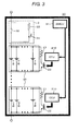
- the battery module 30 includes a power source circuit where the plurality of groups of battery cells 20 are connected in series to each other, and a fuse blowing detection circuit 3 which is connected in series to the power source circuit.
- the group of battery cells 20 is configured by connecting a plurality of battery cells (B11 to B1X) to each other in parallel.
- a resistance element 21 and a switching element 22 are connected in parallel to the group of battery cells 20.
- the resistance element 21 and the switching element 22 are provided for performing balancing among the battery cells (B11 to B1X) when irregularities in voltage occur among the battery cells (B11 to B1X).
- the cell control unit 210 obtains current/voltage information among the respective battery cells (B11 to B1X) and outputs the current/voltage information to the battery module control unit 31, and the battery module control unit 31 calculates charge states (SOC) of the respective battery cells. Further, the cell control unit 210 outputs a signal based on which the switching element 22 is brought into an ON state when the difference in the charge state among the respective battery cells (B11 to B1X) becomes 10% or more, and performs balancing among the battery cells (B11 to B1X) within the group of battery cells 20.
- the fuse blowing detection circuit 3 is constituted of a fuse 32, and a resistance element 33 and a light emitting diode 34 which are connected in parallel to the fuse 32.
- a cathode side of the light emitting diode 34 is connected to a low potential side of the resistance element 33. Due to such a constitution, in a case where the fuse 32 mounted in any one of the battery modules 30 is blown, the light emitting diode 34 emits light by using a detection method described later.
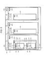
- Fig. 4 and Fig. 5 show the specific circuit constitution of the battery pack 40.
- the battery pack 40 shown in Fig. 4 is constituted of a series circuit where the plurality of battery modules 30 are connected in series, and a resistance element 41 and a switching element 42 which are connected in parallel to the series circuit.
- Fig. 5 shows the battery system 201 where the plurality of battery blocks 50 each having the battery pack 40 are connected to each other in parallel.
- the battery block 50 includes the battery pack 40 and a precharge circuit 55 which is connected in series to the battery pack 40.
- the plurality of battery packs 40 may be connected to each other in parallel in the battery block 50.
- the battery blocks 50 are connected to each other in parallel, and the battery blocks 50 are connected to a positive pole side of the inverter 104 via a switching element 251 and are connected to a negative pole side of the inverter 104 via a switching element 252.
- the precharge circuit 55 is constituted of a switching element 51, and a resistance element 52 and a switching element 53 which are connected in parallel to the switching element 51.
- the precharge circuit 55 can reduce irregularities in charge state or voltage between the battery block 50 and other battery blocks 50 by making use of a cross current when there exist the irregularities in the charging state or the voltage between the battery blocks 50. That is, the precharge circuit 55 brings the switching element 251 and the switching element 252 into an OFF state, brings the switching element 51 into an OFF state, and maintains a period where the switching element 53 is held in an ON state for some time.
- the battery block control unit 240 where an abnormal voltage is generated is separated.
- the switching element 51 and the switching element 53 in the battery block 50 where the abnormal voltage is generated are brought into an OFF state.
- a drive current for the light emitting diode 34 can be identified by a known series battery voltage and a sum of resistance values of the resistance element 33 and the resistance element 41 and hence, whatever external load is connected to the battery system 201, it is possible to surely make the light emitting diode 34 emit light.
- the switching element 42 arranged in the battery pack 40 is brought into an ON state.
- a closed circuit which is constituted of series elements of the battery modules 30, and the resistance element 41 and the switching element 42 is formed in the battery pack 40 so that an electric current flows into the light emitting diode 34 which is connected in parallel to the blown fuse 32 whereby the light emitting diode 34 emits light.
- the light emitting diode 34 can be visually recognized from the outside of a casing of the battery modules 30, even in the battery system which uses a large number of battery modules, the battery module 30 in which abnormality occurs can be easily confirmed and can be exchanged.
- Fig. 9 shows the external appearance of the battery pack 40 constructed in accordance with the present invention.
- the plurality of battery modules 30 are accommodated in a battery rack 110 in a state where the battery modules 30 are placed in parallel to each other on each module mounting base 120.
- the battery pack control unit 230 is also accommodated in the battery rack 110.
- the light emitting diode 34 is mounted in the battery module 30 such that the light emitting diode 34 can be visually recognized from the outside of the casing of the battery modules 30. Due to such a constitution, even when the fuse 32 is blown in the inside of any one of the battery modules 30, the blowing of the fuse 32 can be easily visually recognized from the outside of the battery pack 40 and hence, the battery module 30 can be easily exchanged thus enhancing the maintenance property of the battery system 201.
- Battery packs of other embodiments explained hereinafter may also adopt the substantially same constitution with respect to the external appearance of the battery pack 40.
- the battery module 30 where the fuse is blown can be easily identified.
- Fig. 6 shows the second embodiment according to the present invention.
- the constitution of this embodiment substantially equal to the constitution of the first embodiment is explained using the same drawing numerals used in the first embodiment.
- the specific technical feature which makes this embodiment differ from the first embodiment lies in the constitution of a fuse blowing detection circuit.
- a battery module 130 according to the second embodiment is constituted by connecting a fuse blowing detection circuit 131 and a group of battery cells 20 in series.
- the fuse blowing detection circuit 131 includes a resistance element 37 which is connected in parallel to a fuse 32 and a Zener diode 36.
- a cathode side of the Zener diode 36 is connected to a positive pole side of the group of battery cells 20 and an anode side of the Zener diode 36 is connected to the resistance element 37.
- the fuse blowing detection circuit 131 includes a capacitor 35 and a light emitting diode 34 which are connected in parallel to the Zener diode 36.
- a cathode side of the light emitting diode 34 is connected to the anode side of the Zener diode 36 via a resistance element 33, and an anode side of the light emitting diode 34 is connected to a positive pole side of the batteries.
- the Zener diode 36 in parallel to the capacitor 35, when a voltage of a predetermined value is applied to the capacitor 35, the Zener diode 36 generates a Zener breakdown thus preventing a voltage of the predetermined value or more from being applied to the capacitor 35 whereby it is possible to protect the light emitting diode 34.
- the capacitance of the capacitor may preferably be set such that a voltage which ensures the normal light emission of the light emitting diode 34 is applied to the light emitting diode 34. For example, it is preferable to use the capacitor of 0.1 ⁇ F.
- a breakdown voltage of the Zener diode slightly larger than a forward voltage of the light emitting diode 34 to be used and hence, by setting the breakdown voltage of the Zener diode to 5 V, it is possible to prevent the breakdown of the light emitting diode 34 and make the light emitting diode 34 surely emit light.
- the breakdown of the light emitting diode 34 can be prevented when the fuse 32 is blown and hence, it is possible to surely identify the battery module 130 where the fuse 32 is blown.
- the specific constitution of a battery system 201 may be obtained by modifying the battery pack 40 shown in Fig. 5 to a battery pack 140 according to this embodiment. Accordingly, with respect to a method of identifying the battery module 130 where the fuse 32 is blown, the battery module 130 where the fuse 32 is blown can be identified by a method substantially equal to the method used in the first embodiment.
- Fig. 7 shows the third embodiment according to the present invention.
- the constitution of this embodiment substantially equal to the constitution of the first embodiment is explained using the same drawing numerals used in the first embodiment.
- the specific technical features which make this embodiment differ from the first embodiment lie in the constitution of a fuse blowing detection circuit and the constitution where a plurality of battery packs which constitute a battery block 50 are arranged in parallel to each other.
- the fuse blowing detection circuit 331 is constituted of a fuse 32, and a resistance element 33 and a light emitting diode 34 which are connected in parallel to the fuse 32.
- An anode side of the light emitting diode 34 is connected to a positive pole side of a group of battery cells 20, and the resistance element 33 is connected to a cathode side of the light emitting diode 34.
- the fuse blowing detection circuit 331 includes a light emitting diode 38 which is connected in parallel to the light emitting diode 34.
- the light emitting diode 34 or the light emitting diode 38 can be turned on in both cases, that is, the case where the battery module 330 is in a discharge state and the case where the battery module 330 is in a charge state. Accordingly, the battery module 330 where the fuse 32 is blown can be identified irrelevant to a charge state of each battery module 330.
- the battery pack 340 is constituted by connecting the above-mentioned plurality of battery modules 330 in series.
- the battery block 50 is constituted by connecting the plurality of battery packs 340 to each other in parallel. Further, the battery packs 340 are, as shown in Fig. 7 , connected to a precharge circuit 55 via switching elements 54a1, ... 54an (n being the number of battery packs 340 arranged in parallel to each other).
- a cross current between the battery packs 340 can be utilized with the use of a method of identifying a portion where the fuse 32 is blown which is described hereinafter and hence, there is no possibility that a large voltage is applied to the light emitting diode 34 when the fuse 32 is blown whereby the breakdown of the light emitting diode 34 can be prevented.
- the battery block control unit 240 When the deviation between the voltages of the respective battery packs 340 becomes a value within the predetermined range, the battery block control unit 240 performs a control of bringing the switching elements 54a1, ... 54an into an OFF state. Then, a battery pack control unit 230 brings a switching element 42 into an ON state so that the battery module 330 where the fuse 32 is blown can be surely identified while preventing the breakdown of the light emitting diodes 34, 38 which may be caused when an overvoltage is applied to the light emitting diodes 34, 38.
- Fig. 8 shows the fourth embodiment according to the present invention.
- the constitution of this embodiment substantially equal to the constitution of the second embodiment is explained using the same drawing numerals used in the second embodiment.
- the specific technical feature which makes this embodiment differ from the second embodiment lies in the constitution of a battery pack.
- a battery pack 440 according to this embodiment does not have a resistance element 41 and a switching element 42 which are connected in parallel to series elements of battery modules 130.
Landscapes
- Engineering & Computer Science (AREA)
- Chemical & Material Sciences (AREA)
- Chemical Kinetics & Catalysis (AREA)
- Electrochemistry (AREA)
- General Chemical & Material Sciences (AREA)
- Manufacturing & Machinery (AREA)
- Power Engineering (AREA)
- Microelectronics & Electronic Packaging (AREA)
- Charge And Discharge Circuits For Batteries Or The Like (AREA)
- Secondary Cells (AREA)
- Tests Of Electric Status Of Batteries (AREA)
- Battery Mounting, Suspending (AREA)
Applications Claiming Priority (1)
| Application Number | Priority Date | Filing Date | Title |
|---|---|---|---|
| JP2012072715A JP2013207876A (ja) | 2012-03-28 | 2012-03-28 | 電池システム |
Publications (1)
| Publication Number | Publication Date |
|---|---|
| EP2645465A1 true EP2645465A1 (fr) | 2013-10-02 |
Family
ID=47739149
Family Applications (1)
| Application Number | Title | Priority Date | Filing Date |
|---|---|---|---|
| EP13156080.7A Withdrawn EP2645465A1 (fr) | 2012-03-28 | 2013-02-21 | Système de batteries |
Country Status (4)
| Country | Link |
|---|---|
| US (1) | US20130260196A1 (fr) |
| EP (1) | EP2645465A1 (fr) |
| JP (1) | JP2013207876A (fr) |
| CN (1) | CN103368221A (fr) |
Cited By (1)
| Publication number | Priority date | Publication date | Assignee | Title |
|---|---|---|---|---|
| US10581056B2 (en) | 2013-09-06 | 2020-03-03 | Cps Technology Holdings Llc | Systems, methods, and devices for pre-charge control of a battery module |
Families Citing this family (12)
| Publication number | Priority date | Publication date | Assignee | Title |
|---|---|---|---|---|
| JP2015050842A (ja) * | 2013-09-02 | 2015-03-16 | ソニー株式会社 | 蓄電システム、蓄電制御装置および蓄電制御方法 |
| DE102014200329A1 (de) * | 2014-01-10 | 2015-07-16 | Robert Bosch Gmbh | Elektrochemischer Energiespeicher und Verfahren zum Balancing |
| JP6129095B2 (ja) * | 2014-02-13 | 2017-05-17 | Jmエナジー株式会社 | 蓄電装置の電流遮断検出回路及び電流遮断検出方法 |
| CN104459549A (zh) * | 2014-11-19 | 2015-03-25 | 成都嵌智捷科技有限公司 | 方便检测电量的电路 |
| EP3566259B1 (fr) * | 2017-01-09 | 2023-03-08 | Milwaukee Electric Tool Corporation | Bloc-batterie |
| CN109830764B (zh) * | 2017-11-23 | 2021-08-06 | 台达电子工业股份有限公司 | 具异常检测功能的电池模块与蓄电装置及其操作方法 |
| EP3800723A1 (fr) * | 2019-10-02 | 2021-04-07 | Rolls-Royce Deutschland Ltd & Co KG | Module de batterie et avion doté d'un module de batterie |
| KR20210129542A (ko) | 2020-04-20 | 2021-10-28 | 주식회사 엘지에너지솔루션 | 배터리 모듈, 에너지 저장 장치 및 퓨즈 설정 방법 |
| US11569668B2 (en) * | 2020-07-14 | 2023-01-31 | Igrenenergi, Inc. | System and method for dynamic balancing power in a battery pack |
| US20240006885A1 (en) * | 2020-11-11 | 2024-01-04 | Hitachi Energy Switzerland Ag | Energy storage system with resistor circuit for bi-directional high-power applications |
| US12136837B1 (en) * | 2020-12-08 | 2024-11-05 | Bobbie Wilson | Charge balancing of parallel strings with zener diode and light emitting diode between cell terminal of the battery strings |
| JP7735946B2 (ja) * | 2022-06-30 | 2025-09-09 | 住友電気工業株式会社 | 電池ユニットの接続切替装置及び電池充電システム |
Citations (5)
| Publication number | Priority date | Publication date | Assignee | Title |
|---|---|---|---|---|
| JP2002142353A (ja) * | 2000-10-31 | 2002-05-17 | Nissan Motor Co Ltd | 組電池 |
| JP2003109673A (ja) * | 2001-09-28 | 2003-04-11 | Nec Mobile Energy Kk | 警告機能付き電池パック |
| JP2004311350A (ja) * | 2003-04-10 | 2004-11-04 | Alps Electric Co Ltd | バッテリ装置および携帯機器 |
| JP2008296863A (ja) | 2007-06-04 | 2008-12-11 | Auto Network Gijutsu Kenkyusho:Kk | 車載用のヒューズ断線検出装置 |
| JP2009148099A (ja) * | 2007-12-14 | 2009-07-02 | Panasonic Electric Works Co Ltd | 電池システム |
Family Cites Families (6)
| Publication number | Priority date | Publication date | Assignee | Title |
|---|---|---|---|---|
| CN1040268A (zh) * | 1989-09-08 | 1990-03-07 | 李荣华 | 多功能机动车电路测试器 |
| US8084154B2 (en) * | 2007-02-08 | 2011-12-27 | Karl Frederick Scheucher | Battery pack safety and thermal management apparatus and method |
| US8093819B2 (en) * | 2009-03-23 | 2012-01-10 | Jiangmen Polestar Electric Industries Co., Ltd. | Flashing light string |
| CN202057746U (zh) * | 2011-04-22 | 2011-11-30 | 芮骏 | 熔断器熔断指示器 |
| CN102148522B (zh) * | 2011-05-04 | 2013-05-01 | 柳州五菱汽车有限责任公司 | 一种蓄电池组控制方法及系统 |
| CN202084968U (zh) * | 2011-06-20 | 2011-12-21 | 上海恒动汽车电池有限公司 | 一种动力蓄电池预充电电路 |
-
2012
- 2012-03-28 JP JP2012072715A patent/JP2013207876A/ja active Pending
-
2013
- 2013-02-21 EP EP13156080.7A patent/EP2645465A1/fr not_active Withdrawn
- 2013-02-21 US US13/772,414 patent/US20130260196A1/en not_active Abandoned
- 2013-02-21 CN CN2013100553467A patent/CN103368221A/zh active Pending
Patent Citations (5)
| Publication number | Priority date | Publication date | Assignee | Title |
|---|---|---|---|---|
| JP2002142353A (ja) * | 2000-10-31 | 2002-05-17 | Nissan Motor Co Ltd | 組電池 |
| JP2003109673A (ja) * | 2001-09-28 | 2003-04-11 | Nec Mobile Energy Kk | 警告機能付き電池パック |
| JP2004311350A (ja) * | 2003-04-10 | 2004-11-04 | Alps Electric Co Ltd | バッテリ装置および携帯機器 |
| JP2008296863A (ja) | 2007-06-04 | 2008-12-11 | Auto Network Gijutsu Kenkyusho:Kk | 車載用のヒューズ断線検出装置 |
| JP2009148099A (ja) * | 2007-12-14 | 2009-07-02 | Panasonic Electric Works Co Ltd | 電池システム |
Cited By (2)
| Publication number | Priority date | Publication date | Assignee | Title |
|---|---|---|---|---|
| US10581056B2 (en) | 2013-09-06 | 2020-03-03 | Cps Technology Holdings Llc | Systems, methods, and devices for pre-charge control of a battery module |
| US11241965B2 (en) | 2013-09-06 | 2022-02-08 | Cps Technology Holdings Llc | Systems, methods, and devices for pre-charge control of a battery module |
Also Published As
| Publication number | Publication date |
|---|---|
| US20130260196A1 (en) | 2013-10-03 |
| JP2013207876A (ja) | 2013-10-07 |
| CN103368221A (zh) | 2013-10-23 |
Similar Documents
| Publication | Publication Date | Title |
|---|---|---|
| EP2645465A1 (fr) | Système de batteries | |
| KR102816659B1 (ko) | 배터리 시스템 | |
| KR101364094B1 (ko) | 배터리 시스템 및 이를 포함하는 에너지 저장 시스템 | |
| EP2645448A1 (fr) | Bloc batterie et système de batterie | |
| US9837811B2 (en) | Power source apparatus formed by combining a plurality of modules | |
| KR101483129B1 (ko) | 배터리 시스템 및 에너지 저장 시스템 | |
| US20130257440A1 (en) | Relay Welding Detector of Battery System and Battery System Which Uses the Detector | |
| US9680320B2 (en) | Battery control apparatus | |
| KR101062101B1 (ko) | 고출력 에너지 축전지들을 포함하는 잠수함 직류 회로망 | |
| EP2608347A2 (fr) | Système de stockage d'énergie électrique et son procédé d'entretien | |
| US9209632B2 (en) | Systems and methods of direct cell attachment for batteries | |
| EP2645515A2 (fr) | Système de batterie | |
| KR101269059B1 (ko) | 태양광 가로등용 리튬 이차전지 팩 | |
| US7414334B2 (en) | Circuit arrangement for limitation of over-voltages in energy storage modules | |
| US9759780B2 (en) | System for power balance monitoring in an energy storage battery | |
| KR101924931B1 (ko) | 배터리 에너지 저장 시스템 | |
| KR20130015353A (ko) | 배터리 관리 장치 및 이를 포함하는 배터리 에너지 저장 시스템 | |
| US10763677B2 (en) | Charging/discharging of battery energy storage system using 3-phase transformer | |
| US20130234517A1 (en) | Power accumulation system and method for controlling storage module | |
| KR101837548B1 (ko) | 커패시터 관리 시스템 | |
| EP4625736A1 (fr) | Système de stockage d'énergie, dispositif de protection et procédé de protection associés | |
| Weiss et al. | High safety photovoltaic insular power supply system employing re-used lithium-ion cells | |
| CN210183029U (zh) | 电池包保护芯片 | |
| CA3170801A1 (fr) | Systeme et methode de circuit d'equilibrage d'element de batterie | |
| CN207165704U (zh) | 一种电池极耳温度管理系统 |
Legal Events
| Date | Code | Title | Description |
|---|---|---|---|
| PUAI | Public reference made under article 153(3) epc to a published international application that has entered the european phase |
Free format text: ORIGINAL CODE: 0009012 |
|
| 17P | Request for examination filed |
Effective date: 20130412 |
|
| AK | Designated contracting states |
Kind code of ref document: A1 Designated state(s): AL AT BE BG CH CY CZ DE DK EE ES FI FR GB GR HR HU IE IS IT LI LT LU LV MC MK MT NL NO PL PT RO RS SE SI SK SM TR |
|
| AX | Request for extension of the european patent |
Extension state: BA ME |
|
| STAA | Information on the status of an ep patent application or granted ep patent |
Free format text: STATUS: THE APPLICATION IS DEEMED TO BE WITHDRAWN |
|
| 18D | Application deemed to be withdrawn |
Effective date: 20140403 |