EP2645484B1 - Connecteurs électriques et procédés pour coupler des connecteurs électriques à barres omnibus - Google Patents
Connecteurs électriques et procédés pour coupler des connecteurs électriques à barres omnibus Download PDFInfo
- Publication number
- EP2645484B1 EP2645484B1 EP13160765.7A EP13160765A EP2645484B1 EP 2645484 B1 EP2645484 B1 EP 2645484B1 EP 13160765 A EP13160765 A EP 13160765A EP 2645484 B1 EP2645484 B1 EP 2645484B1
- Authority
- EP
- European Patent Office
- Prior art keywords
- coupling
- mounting portion
- busbar
- apertures
- electrical connector
- Prior art date
- Legal status (The legal status is an assumption and is not a legal conclusion. Google has not performed a legal analysis and makes no representation as to the accuracy of the status listed.)
- Not-in-force
Links
Images





Classifications
-
- H—ELECTRICITY
- H01—ELECTRIC ELEMENTS
- H01R—ELECTRICALLY-CONDUCTIVE CONNECTIONS; STRUCTURAL ASSOCIATIONS OF A PLURALITY OF MUTUALLY-INSULATED ELECTRICAL CONNECTING ELEMENTS; COUPLING DEVICES; CURRENT COLLECTORS
- H01R25/00—Coupling parts adapted for simultaneous co-operation with two or more identical counterparts, e.g. for distributing energy to two or more circuits
- H01R25/16—Rails or bus-bars provided with a plurality of discrete connecting locations for counterparts
- H01R25/161—Details
- H01R25/162—Electrical connections between or with rails or bus-bars
-
- H—ELECTRICITY
- H01—ELECTRIC ELEMENTS
- H01R—ELECTRICALLY-CONDUCTIVE CONNECTIONS; STRUCTURAL ASSOCIATIONS OF A PLURALITY OF MUTUALLY-INSULATED ELECTRICAL CONNECTING ELEMENTS; COUPLING DEVICES; CURRENT COLLECTORS
- H01R25/00—Coupling parts adapted for simultaneous co-operation with two or more identical counterparts, e.g. for distributing energy to two or more circuits
- H01R25/14—Rails or bus-bars constructed so that the counterparts can be connected thereto at any point along their length
- H01R25/145—Details, e.g. end pieces or joints
-
- H—ELECTRICITY
- H01—ELECTRIC ELEMENTS
- H01R—ELECTRICALLY-CONDUCTIVE CONNECTIONS; STRUCTURAL ASSOCIATIONS OF A PLURALITY OF MUTUALLY-INSULATED ELECTRICAL CONNECTING ELEMENTS; COUPLING DEVICES; CURRENT COLLECTORS
- H01R4/00—Electrically-conductive connections between two or more conductive members in direct contact, i.e. touching one another; Means for effecting or maintaining such contact; Electrically-conductive connections having two or more spaced connecting locations for conductors and using contact members penetrating insulation
- H01R4/28—Clamped connections, spring connections
- H01R4/38—Clamped connections, spring connections utilising a clamping member acted on by screw or nut
- H01R4/46—Clamping area between two screws placed side by side
-
- H—ELECTRICITY
- H01—ELECTRIC ELEMENTS
- H01R—ELECTRICALLY-CONDUCTIVE CONNECTIONS; STRUCTURAL ASSOCIATIONS OF A PLURALITY OF MUTUALLY-INSULATED ELECTRICAL CONNECTING ELEMENTS; COUPLING DEVICES; CURRENT COLLECTORS
- H01R4/00—Electrically-conductive connections between two or more conductive members in direct contact, i.e. touching one another; Means for effecting or maintaining such contact; Electrically-conductive connections having two or more spaced connecting locations for conductors and using contact members penetrating insulation
- H01R4/28—Clamped connections, spring connections
- H01R4/30—Clamped connections, spring connections utilising a screw or nut clamping member
Definitions
- Electrical busbars such as elongated rectangular flat conductive bus bars, have long been utilized in the electrical distribution industry to conduct electricity.
- Two electrical busbars have been conventionally connected together by drilling or otherwise forming holes through the two electrical busbars and coupling the busbars together utilizing bolts disposed through the holes.
- DE 298 16 627 U1 discloses clamping members consisting of rectangular metal plates which run on both sides of a bus bar with spacing relative to its surface. Contact pieces protrude from the clamping members in the direction of the bus bar to attach the clamping members to the bus bar.
- the drilling process is a labor intensive and time consuming task. Additionally, the need for bolts adds cost and labor for installation.
- DE 4124066 A1 describes an electric lighting system with a conducting bar to clamp a lampholder.
- the conducting bar is clamped by two clamping members adjoining the conducting bar at two sides within a gap between the two clamping members which are fixed by bolts.
- the present invention provides an electrical connector as defined in claim 1.
- the electrical connector in accordance with an exemplary embodiment is provided.
- the electrical connector includes a first mounting portion.
- the electrical connector further includes a first clamping portion coupled to the first mounting portion.
- the first clamping portion has a first coupling tab and a second coupling tab.
- the first coupling tab extends from the first mounting portion in a first direction.
- the first coupling tab has first and second apertures extending therethrough.
- the second coupling tab extends from the first mounting portion in the first direction.
- the first and second coupling tabs define a first gap.
- the second coupling tab has third and fourth apertures extending there through.
- the third and fourth apertures are aligned with the first and second apertures, respectively.
- the first and third apertures are configured to receive a first fastener.
- the second and fourth apertures are configured to receive a second fastener.
- the first gap is sized to receive a first busbar.
- the first and second coupling tabs are configured to form an electrical connection with the first busbar in the first gap.
- the method further includes cutting the extruded portion into the plurality of connector portions utilizing a cutting device.
- Each connector portion has a mounting portion and a clamping portion.
- Each clamping portion has first and second coupling tabs that extend from a respective mounting portion.
- an electrical circuit 10 having a first busbar 20, a second busbar 22, and an electrical connector 30 in accordance with an exemplary embodiment is illustrated.
- An advantage of the electrical connector 30 is that the connector 30 is coupled to the first busbar 20 and the second busbar 22 without drilling holes in the busbars 20, 22.
- the first busbar 20 and the second busbar 22 are each constructed of an electrically conductive material for conducting electricity therethrough.
- the first busbar 20 and the second busbar 22 are constructed of copper.
- the electrical connector 30 includes a first connector portion 31, a second connector portion 32, and fasteners such as bolts 33, 34, 35, 36 for example.
- the first connector portion 31 is coupled to the second connector portion 32 utilizing the bolts 33, 34, 35, 36.
- the first connector portion 31 is configured to be coupled to the second connector portion 32 and to the busbar 20.
- the first connector portion 31 includes a mounting portion 40; a clamping portion 41 having coupling tabs 42, 44; fasteners such as bolts 60, 62; and nuts 64, 66.
- the mounting portion 40 may be block-shaped and includes apertures 80, 82, 84, 86 extending therein. In one exemplary embodiment, the block-shaped mounting portion 40 is parallelepiped shaped.
- the mounting portion 40 is constructed of an electrically conductive material. In one exemplary embodiment, the mounting portion 40 is constructed of copper. Of course, in an alternative embodiment, the mounting portion 40 could be constructed of another electrically conductive material suitable for a purpose disclosed herein.
- the clamping portion 41 having coupling tabs 42, 44 is configured to hold the busbar 20 between the coupling tabs 42, 44.
- the coupling tab 42 extends from the mounting portion 40 in a first direction.
- the coupling tab 42 has apertures 100, 102 extending therethrough.
- the coupling tab 44 extends from the mounting portion 40 in the first direction such that a gap 50 is formed between the coupling tabs 42, 44.
- the gap 50 has a size sufficient to receive an end portion of the busbar 20 therein.
- the coupling tab 44 has apertures 110, 112 extending therethrough.
- the apertures 110, 112 in the coupling tab 44 are aligned with the apertures 100, 102 respectively in the coupling tab 42.
- the coupling tabs 42, 44 have grooves 121, 123, respectively, disposed proximate to the mounting portion 40, wherein the coupling tabs 42, 44 are bendable proximate the grooves 121, 123, respectively, toward one another.
- the coupling tabs 42, 44 are each constructed of an electrically conductive material.
- coupling tabs 42, 44 are constructed of copper.
- the coupling tabs 42, 44 could each be constructed of another electrically conductive material suitable for a purpose disclosed herein.
- the bolt 60 is configured to be disposed through the apertures 100, 110 and is coupled to the nut 64.
- the bolt 62 is configured to be disposed through the apertures 102, 112 and is coupled to the nut 66.
- the coupling tabs 42, 44 are urged towards one another such that the coupling tabs 42, 44 are fixedly clamped against the first busbar 20 disposed through the gap 50 between the coupling tabs 42, 44.
- the mounting portion 40 is electrically coupled to the first busbar 20 via the coupling tabs 42, 44.
- the second connector portion 32 is configured to be coupled to the first connector portion 31 and to the busbar 22.
- the second connector portion 32 includes a mounting portion 240; a clamping portion 241 having coupling tabs 242, 244; fasteners such as bolts 260, 262; and nuts 264, 266.
- the mounting portion 240 may be block-shaped and includes apertures 280, 282, 284, 286 extending therein.
- the block-shaped mounting portion 240 is parallelepiped shaped.
- the mounting portion 240 is constructed of an electrically conductive material.
- the mounting portion 240 is constructed of copper.
- the mounting portion 240 could be constructed of another electrically conductive material suitable for a purpose disclosed herein.
- the clamping portion 241 having coupling tabs 242, 244 is configured to hold the busbar 22 between the coupling tabs 242, 244.
- the coupling tab 242 extends from the mounting portion 240 in a first direction.
- the coupling tab 242 has apertures 300, 302 extending therethrough.
- the coupling tab 244 extends from the mounting portion 240 in the first direction such that a gap 250 is formed between the coupling tabs 242, 244.
- the gap 250 has a size sufficient to receive the busbar 22 therein.
- the coupling tab 244 has apertures 310, 312 extending therethrough.
- the apertures 310, 312 in the coupling tab 244 are aligned with the apertures 300, 302 respectively in the coupling tab 242.
- the coupling tabs 242, 244 have grooves 321, 323, respectively, disposed proximate to the mounting portion 240, wherein the coupling tabs 242, 244 are bendable proximate the grooves 321, 323, respectively, toward one another.
- the coupling tabs 242, 244 are each constructed of an electrically conductive material.
- coupling tabs 242, 244 are constructed of copper.
- the coupling tabs 242, 244 could each be constructed of another electrically conductive material suitable for a purpose disclosed herein.
- the bolt 260 is configured to be disposed through the apertures 300, 310 and is coupled to the nut 264.
- the bolt 262 is configured to be disposed through the apertures 302, 312 and is coupled to the nut 266.
- the coupling tabs 242, 244 are urged towards one another such that the coupling tabs 242, 244 are fixedly clamped against the second busbar 22 disposed through the gap 250 between the coupling tabs 242, 244.
- the mounting portion 240 is electrically coupled to the second busbar 22 via the coupling tabs 242, 244.
- FIGS. 9 and 10 a flowchart of a method for coupling the electrical connector 30 to busbars 20, 22 in accordance with another exemplary embodiment will be explained.
- the user provides the first connector portion 31 having a mounting portion 40; the clamping portion 41 having coupling tabs 42, 44; bolts 60, 62; and nuts 64, 66.
- the coupling tab 42 extends from the mounting portion 40 in a first direction.
- the coupling tab 42 has apertures 100, 102 extending therethrough.
- the coupling tab 44 extends from the mounting portion 40 in the first direction such that the gap 50 is formed between the coupling tabs 42, 44.
- the coupling tab 44 has apertures 110, 112 extending therethrough.
- the apertures 110, 112 are aligned with the apertures 100, 102, respectively.
- the bolt 60 is disposed through the apertures 100, 110 and is coupled to the nut 64.
- the bolt 62 is disposed through the apertures 102, 112 and is coupled to the nut 66.
- the user provides the second connector portion 32 having a mounting portion 240; a clamping portion 241 having coupling tabs 242, 244; bolts 260, 262; and nuts 264, 266.
- the coupling tab 242 extends from the mounting portion 240 in a first direction.
- the coupling tab 242 has apertures 300, 302 extending therethrough.
- the coupling tab 244 extends from the mounting portion 240 in the first direction such that the gap 250 is formed between the coupling tabs 242, 244.
- the coupling tab 244 has apertures 310, 312 extending therethrough.
- the apertures 310, 312 are aligned with the apertures 300, 302, respectively.
- the bolt 260 is disposed through the apertures 300, 310 and it is coupled to the nut 264.
- the bolt 262 is disposed through the apertures 302, 312 and is coupled to the nut 266.
- the mounting portion 240 can be coupled to the mounting portion 40 or formed as a unitary body.
- the coupling tabs 242 and 244 extend from the mounting portion 240 in an opposite direction relative to the direction in which the coupling tabs 42 and 44 extend from the mounting portion 40.
- the mounting portion 40 is a first mounting portion
- the mounting portion 240 is a second mounting portion.
- the clamping portion 41 is a first clamping portion
- the clamping portion 241 is a second clamping portion.
- the coupling tabs 42, 44, 242, 244 are first, second, third, and fourth coupling tabs, respectively.
- the apertures 100, 102, 110, 112, 300, 302, 310, 312 are first, second, third, fourth, fifth, sixth, seventh, and eighth apertures, respectively.
- the gap 50 is a first gap
- the gap 250 is a second gap.
- the bolts 60, 62, 260, 262 are first, second, third, and fourth fasteners, respectively.
- the user inserts the first busbar 20 within the gap 50 such that the first busbar 20 is disposed between the coupling tabs 42, 44 and further disposed between the bolts 60, 62.
- step 356 the user rotates the bolts 60, 62 within the nuts 64, 66, respectively, such that the coupling tabs 42, 44 are fixedly clamped against the first busbar 20. Also, the mounting portion 40 is electrically coupled to the first busbar 20.
- the user inserts the second busbar 22 within the gap 250 such that the second busbar 22 is disposed between the coupling tabs 242, 244 and is further disposed between the bolts 260, 262.
- step 360 the user rotates the bolts 260, 262 within the nuts 264, 266, respectively, such that the coupling tabs 242, 244 are fixedly clamped against the second busbar 22, and the mounting portion 240 is electrically coupled to the second busbar 22.
- the system 700 includes a melting device 710, an extruding device 720, a first conveyor device 730, a cooling device 740, a second conveyor device 750, a cutting device 760, and a drilling device 770.
- the melting device 710 is configured to melt a metal to form a liquid metal 712.
- the liquid metal 712 is liquid copper.
- the extruding device 720 is configured to receive the liquid metal 712 from the melting device 710 and to move the liquid metal 712 through an extruding die 724 within the extruding device 720 to form an extruded portion 726.
- the extruded portion 726 has a cross-sectional profile corresponding to a connector portion.
- the extruding die 724 is constructed of plates 780, 782, 784, 786, 788, 790 coupled together.
- the extruding die 724 has an inlet aperture 820 and an outlet aperture 824.
- the outlet aperture 824 has a profile corresponding to a connector portion such that when the liquid metal 712 exits the outlet aperture 824, the extruded portion 726 has a cross-sectional profile corresponding to a connector portion.
- the first conveyor device 730 is configured to move the extruded portion 726 exiting the extruding device 720 from the extruding device 720 to the cooling device 740.
- the cooling device 740 is configured to cool the extruded portion 726 such that the extruded portion 726 is solidified. In one exemplary embodiment, the cooling device 740 applies a liquid on the extruded portion 726 to cool the extruded portion 726.
- the second conveyor device 750 is configured to move the extruded portion 726 from the cooling device 740 to the cutting device 760.
- the cutting device 760 cuts the extruded portion 760 into the plurality of connector portions 31.
- Each connector portion 31 has a mounting portion 40 and a clamping portion 41.
- Each clamping portion 41 has first and second coupling tabs 42, 44 that extend from a respective mounting portion 40.
- the drilling device 770 drills apertures 100, 102 in the coupling tab 42 and apertures 110, 112 in the coupling tab 44.
- the apertures 100, 110 are aligned with one another, and the apertures 102, 112 are aligned with one another.
- the drilling device 770 drills the apertures 80, 82, 84, 86 through each mounting portion 40 of each connector portion 31.
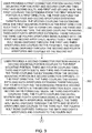
- FIGS. 5 , 19 , 20 , 24 and 25 a flowchart of a method for manufacturing a plurality of connector portions of electrical connectors in accordance with another exemplary embodiment will now be explained.
- the melting device 710 melts a metal to form a liquid metal 712 and the extruding device 720 moves the liquid metal 712 through the extruding die 720 to form the extruded portion 726 having a cross-sectional profile corresponding to a connector portion 31.
- the first conveyor device 730 moves the extruded portion 726 to the cooling device 740.
- the cooling device 740 cools the extruded portion 726.
- the second conveyor device 750 moves the extruded portion 726 from the cooling device 740 to the cutting device 760.
- each connector portion 31 has a mounting portion 40 and a clamping portion 41.
- Each clamping portion 41 has first and second coupling tabs 42, 44 that extend from a respective mounting portion 40.
- the drilling device 770 drills at least first and second apertures 100, 110 in the first and second coupling tabs 42, 44, respectively, of each clamping portion 41, that are aligned with one another.
- the drilling device 770 drills at least one aperture 80 through each mounting portion 40 of each connector portion 31.
- the electrical circuit 400 includes a first busbar 420 having a top surface 420A and a bottom surface 420B; a second busbar 422 having a top surface 422A and a bottom surface 422B; a third busbar 424; an electrical connector 430; and at least one fastener 432 such as a bolt, and a corresponding nut (not shown).
- the first busbar 420, the second busbar 422, and the third busbar 424 are each constructed of electrically conductive material for conducting electricity therethrough.
- the first busbar 420, the second busbar 422, and the third busbar 424 are constructed of copper.
- first busbar 420 is coupled at a first end to the second bus bar 422 by the electrical connector 430, and coupled at a second end to third busbar 424 via fasteners, such as bolts.
- first busbar 420 is coupled at a first end to third bus bar 424 by a first electrical connector 430, and coupled at a second end to first busbar 420 via a second electrical connector 430 (not shown).
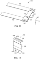
- the electrical connector 430 is configured to electrically couple the first busbar 420 extending in a first direction "X", and the second busbar 422 extending in a second direction "Y".
- first and second directions X, Y are substantially orthogonal.
- An advantage of the electrical connector 430 is that the connector 430 can be coupled to the second busbar 422 without the need to form holes in the busbar 422, such as by drilling.
- the electrical connector 430 includes a first mounting portion 450, a clamping portion 452, and a second mounting portion 454.
- the electrical connector 430 is constructed of an electrically conductive material for conducting electricity therethrough.
- the electrical connector 430 is constructed of copper.
- the electrical connector 430 may be constructed of any desired electrically conductive material suitable for a purpose disclosed herein.
- the first mounting portion 450 comprises a receiving portion 460.
- the receiving portion 460 is sized and disposed to receive an end portion 461 of the first busbar 420.
- the receiving portion 460 defines a first aperture 460A extending therethrough sized and disposed to receive the end portion 461 of the first busbar 420 therethrough ( Fig. 13 ).
- the receiving portion 460 defines a slot 460B sized and disposed to receive the end portion 461 of the first busbar 420 therein ( Fig. 13A ).
- One advantage of an embodiment having aperture 460A is that connector 430 is adjustably positionable on at least one of first busbar 420 and second busbar 422.
- the clamping portion 452 is coupled to the first mounting portion 450 and is configured and arranged to extend over a portion of the first busbar 420.
- the clamping portion 452 is configured to operatively impart a clamping force in a third direction indicated by arrow F, i.e., toward the second busbar 422 when the second busbar 422 is disposed between the clamping portion 452 and the first busbar 420.
- the third direction F is substantially orthogonal to both the first and second directions.
- the clamping portion 452 further comprises a resilient pivoting member 433 and disposed to operatively impart a clamping force in the third direction F through clamping portion 452 toward the second busbar 422 during an installation of connector 430.
- a mounting force generally in the third direction F is applied by a user to the second mounting plate portion, such as through the at least one fastener 432, thereby causing a flexing or bending of resilient pivoting member 433 whereby clamping portion 452 imparts a clamping force in the third direction F.
- the clamping portion 452 comprises a first hinge portion 470, a first contact portion 472, a second contact portion 474, and a coupling portion 476.
- the first hinge portion 470 extends outwardly from an end of the first mounting portion 450 at an acute angle relative to the first mounting portion 450.
- the first contact portion 472 is coupled to and disposed between the first hinge portion 470 and the second contact portion 474.
- the first contact portion 472 is disposed generally perpendicular to the first mounting portion 450.
- the second contact portion 474 is coupled to and disposed between the first contact portion 472 and the coupling portion 476.
- the coupling portion 476 extends generally perpendicular to the second contact portion 474 and is coupled to the second mounting portion 454.
- the second mounting portion 454 extends generally perpendicular to the portion 476.
- clamping portion 452 is configured to contact the top surface 422A of the second busbar 422.
- an intermediate plate such as a conductive shim (not shown) may be disposed between the clamping portion 452 and the second busbar 422.
- the second mounting portion 454 is coupled to the clamping portion 452.
- the second mounting portion 454 is configured to be coupled to the first busbar 420 such that the second busbar 422 is fixedly held between the clamping portion 452 and the first busbar 420, and the second busbar 422 is electrically coupled to the first busbar 420.
- the second mounting portion 454 defines at least one second mounting portion aperture 500 extending therethrough and sized and disposed to operably align with a corresponding at least one aperture 421 defined in the first busbar 420.
- the at least one fastener 432 such as a bolt, is disposed to extend through the second mounting portion aperture 500 and the corresponding at least one aperture 421 defined in first busbar 420 and is coupled to a first nut 433.
- FIGS. 14-18 a flowchart of a method for coupling the electrical connector 430 to the first busbar 420 and the second busbar 422 in accordance with another exemplary embodiment will now be explained.
- the user provides the electrical connector 430 having the first mounting portion 450 comprising the receiving portion 460 formed therein, the clamping portion 452 coupled to an end of the first mounting portion 450, and the second mounting portion 454 coupled to an end of the clamping portion 452.
- the second mounting portion 454 having at least one second mounting portion aperture 500 defined therethrough.
- the user inserts an end portion 461 of the first busbar 420 into the receiving portion 460 of the first mounting portion 450 (as shown in FIGS. 14 and 15 ) such that the clamping portion 452 extends over a portion of the first busbar 420 extending in a first direction.
- the user disposes a second busbar 422 to extend in a second direction substantially perpendicular to the first direction, and between the clamping portion 452 and the first busbar 420 (as shown in FIGS. 14 and 15 ).
- the user applies a force in the third direction F substantially orthogonal the first and second directions, to move the clamping portion 452 toward the second busbar 422 (as shown in FIGS. 16 and 17 ) such that clamping portion 452 imparts a clamping force in the third direction F, i.e., toward the second busbar 422 to electrically couple the second busbar 422 and the first busbar 420.
- the user fastens the connector 430 to the first busbar 420 by disposing a portion of the bolt 432 through the at least one second mounting portion aperture 500 and through an corresponding aperture of the first busbar 420 and coupling a threaded end of the bolt 432 to a first nut.
- Embodiments of the electrical connectors and methods for coupling the connectors to busbars described herein provide a substantial advantage over prior art electrical connectors and methods.
- the electrical connectors couple together two busbars without having to drill holes in both busbars.
Landscapes
- Connections By Means Of Piercing Elements, Nuts, Or Screws (AREA)
- Connector Housings Or Holding Contact Members (AREA)
- Coupling Device And Connection With Printed Circuit (AREA)
Claims (12)
- Connecteur électrique (30), comprenant :une première partie de montage (40) ;une première partie de fixation (41) accouplée à la première partie de montage (40), la première partie de fixation (41) comportant une première languette d'accouplement (42) et une deuxième languette d'accouplement (44) ;la première languette d'accouplement (42) s'étendant à partir de la première partie de montage (40) dans une première direction, la première languette d'accouplement (42) étant traversée par des première et deuxième ouvertures (100, 102) ;la deuxième languette d'accouplement (44) s'étendant à partir de la première partie de montage (40) dans la première direction, les première et deuxième languettes d'accouplement (42, 44) définissant un premier espace (50), la deuxième languette d'accouplement (44) étant traversée par des troisième et quatrième ouvertures (110, 112), les troisième et quatrième ouvertures (110, 112) étant respectivement alignées avec les première et deuxième ouvertures (100, 102) ;les première et troisième ouvertures (100, 110) étant conçues pour recevoir un premier élément de fixation ;les deuxième et quatrième ouvertures (102, 112) étant conçues pour recevoir un deuxième élément de fixation ;le premier espace (50) étant dimensionné pour fixer une première barre omnibus (20) entre la première languette d'accouplement (42) et la deuxième languette d'accouplement (44), la première barre omnibus (20) étant disposée entre le premier élément de fixation et le deuxième élément de fixation ;les première et deuxième languettes d'accouplement (42, 44) étant conçues pour former une connexion électrique avec la première barre omnibus (20) dans le premier espace (50), ledit connecteur électrique étant caractérisé par :une seconde partie de montage (240) ;une seconde partie de fixation (241) accouplée à la seconde partie de montage (240), la seconde partie de fixation comportant une troisième languette d'accouplement (242) et une quatrième languette d'accouplement (244) ;la troisième languette d'accouplement (242) s'étendant à partir de la seconde partie de montage (240) dans une seconde direction opposée à la première direction, la troisième languette d'accouplement (242) étant traversée par des cinquième et sixième ouvertures (300, 302) ;la quatrième languette d'accouplement (244) s'étendant à partir de la seconde partie de montage (240) dans la seconde direction, les troisième et quatrième languettes d'accouplement (242, 244) définissant un second espace (250), la quatrième languette d'accouplement (244) étant traversée par des septième et huitième ouvertures (310, 312), les septième et huitième ouvertures (310, 312) étant respectivement alignées avec les cinquième et sixième ouvertures (300, 302) ;les cinquième et septième ouvertures (300, 310) étant conçues pour recevoir un troisième élément de fixation ;les sixième et huitième ouvertures (302, 312) étant conçues pour recevoir un quatrième élément de fixation ;le second espace étant dimensionné pour recevoir une seconde barre omnibus (22) ;les troisième et quatrième languettes d'accouplement (242, 244) étant conçues pour former une connexion électrique avec la seconde barre omnibus dans le second espace.
- Connecteur électrique (30) selon la revendication 1, dans lequel les premier et deuxième éléments de fixation sont conçus pour s'étendre entre la première languette d'accouplement (42) et la deuxième languette d'accouplement (44).
- Connecteur électrique (30) selon la revendication 1 ou 2, dans lequel les premier et deuxième éléments de fixation sont respectivement des premier et deuxième boulons (60, 62).
- Connecteur électrique (30) selon l'une quelconque des revendications précédentes, dans lequel la première partie de montage (40) et les première et deuxième languettes d'accouplement (42, 44) sont fabriquées dans un matériau électroconducteur.
- Connecteur électrique (30) selon l'une quelconque des revendications précédentes, dans lequel le matériau électroconducteur est le cuivre.
- Connecteur électrique (30) selon l'une quelconque des revendications précédentes, dans lequel la première partie de montage (40) est en forme de bloc.
- Connecteur électrique (30) selon l'une quelconque des revendications précédentes, dans lequel les première et deuxième languettes d'accouplement (42, 44) ont respectivement des première et seconde rainures (121, 123) disposées à proximité de la première partie de montage (40), les première et deuxième languettes d'accouplement (42, 44) pouvant être pliées l'une vers l'autre à proximité respective des première et seconde rainures (121, 123).
- Connecteur électrique (30) selon l'une quelconque des revendications précédentes, dans lequel les troisième et quatrième éléments de fixation sont conçus pour s'étendre entre la troisième languette d'accouplement (242) et la quatrième languette d'accouplement (244).
- Connecteur électrique (30) selon l'une quelconque des revendications précédentes, dans lequel les troisième et quatrième éléments de fixation sont respectivement des troisième et quatrième boulons.
- Connecteur électrique (30) selon l'une quelconque des revendications précédentes, dans lequel la seconde partie de montage (454) et les troisième et quatrième languettes d'accouplement (242, 244) sont fabriquées dans un matériau électroconducteur.
- Connecteur électrique (30) selon l'une quelconque des revendications précédentes, dans lequel la seconde partie de montage (240) est en forme de bloc.
- Connecteur électrique (30) selon l'une quelconque des revendications précédentes, dans lequel les troisième et quatrième languettes d'accouplement (242, 244) ont respectivement des première et seconde rainures (321, 323) disposées à proximité de la seconde partie de montage (240), les troisième et quatrième languettes d'accouplement (242, 244) pouvant être pliées l'une vers l'autre à proximité respective des première et seconde rainures (321, 323).
Applications Claiming Priority (1)
| Application Number | Priority Date | Filing Date | Title |
|---|---|---|---|
| US13/430,335 US8690612B2 (en) | 2011-12-28 | 2012-03-26 | Electrical connectors and methods for coupling the electrical connectors to busbars |
Publications (3)
| Publication Number | Publication Date |
|---|---|
| EP2645484A2 EP2645484A2 (fr) | 2013-10-02 |
| EP2645484A3 EP2645484A3 (fr) | 2013-12-11 |
| EP2645484B1 true EP2645484B1 (fr) | 2017-10-11 |
Family
ID=48040005
Family Applications (1)
| Application Number | Title | Priority Date | Filing Date |
|---|---|---|---|
| EP13160765.7A Not-in-force EP2645484B1 (fr) | 2012-03-26 | 2013-03-25 | Connecteurs électriques et procédés pour coupler des connecteurs électriques à barres omnibus |
Country Status (2)
| Country | Link |
|---|---|
| EP (1) | EP2645484B1 (fr) |
| BR (1) | BR102013006916B1 (fr) |
Families Citing this family (2)
| Publication number | Priority date | Publication date | Assignee | Title |
|---|---|---|---|---|
| CN104713358A (zh) * | 2015-02-13 | 2015-06-17 | 中国科学院上海硅酸盐研究所 | 一种低功耗高温电阻炉 |
| CN121055093A (zh) * | 2025-10-29 | 2025-12-02 | 深圳市德兰明海新能源股份有限公司 | 电连接组件、光伏百叶窗及发电系统 |
Family Cites Families (2)
| Publication number | Priority date | Publication date | Assignee | Title |
|---|---|---|---|---|
| DE4124066C2 (de) * | 1991-07-19 | 1997-03-20 | Ind Und Design Licht Inh Domin | Elektrisches Leuchtensystem |
| DE29816627U1 (de) * | 1998-09-17 | 1998-12-10 | Baranowski, Mike, 44805 Bochum | Niedervolt-Beleuchtungssystem |
-
2013
- 2013-03-25 BR BR102013006916-7A patent/BR102013006916B1/pt not_active IP Right Cessation
- 2013-03-25 EP EP13160765.7A patent/EP2645484B1/fr not_active Not-in-force
Non-Patent Citations (1)
| Title |
|---|
| None * |
Also Published As
| Publication number | Publication date |
|---|---|
| EP2645484A2 (fr) | 2013-10-02 |
| BR102013006916B1 (pt) | 2022-07-12 |
| EP2645484A3 (fr) | 2013-12-11 |
| BR102013006916A2 (pt) | 2015-07-07 |
Similar Documents
| Publication | Publication Date | Title |
|---|---|---|
| EP2610968B1 (fr) | Connecteurs électriques et procédés pour coupler des connecteurs électriques à barres omnibus | |
| US9006571B2 (en) | Bus system connecting bus bars and a method of connecting bus bars | |
| US10283306B2 (en) | Bent MIDI or safety fuse | |
| US10290986B2 (en) | Systems and methods for connecting power distribution devices | |
| US7473146B2 (en) | Busbar assembly | |
| US10439341B2 (en) | Hybrid neutral plug on bar with distributed pitch | |
| EP2645484B1 (fr) | Connecteurs électriques et procédés pour coupler des connecteurs électriques à barres omnibus | |
| US8690612B2 (en) | Electrical connectors and methods for coupling the electrical connectors to busbars | |
| CN102176551A (zh) | 接线端子、电力装置以及接线端子的制造方法、连接方法 | |
| WO2008118344A1 (fr) | Rondelle d'attachement électrique à deux trous universelle | |
| CN101257192B (zh) | 低压配电柜主母线夹 | |
| CN101485058B (zh) | 用于母线的绝缘元件以及包括该元件的用于母线的绝缘支撑设备 | |
| CN204516929U (zh) | 用于连接电缆与母排或母线的压接型连接器 | |
| KR102175332B1 (ko) | 부스바 체결장치 | |
| US20120302110A1 (en) | Connection arrangement for the connection of bus bars | |
| JP2021150100A (ja) | コネクタ | |
| EP3673507B1 (fr) | Agencement accumulateur d'énergie et véhicule pourvu de l'agencement accumulateur d'énergie | |
| US9437991B2 (en) | Load center bus having integral stabs with formed shapes | |
| KR200229460Y1 (ko) | 부스바 절연 지지구 | |
| KR102819202B1 (ko) | 볼트 결합된 전기 연결부의 수리를 용이하게 하도록 구성된 접촉 디바이스 | |
| CN203800396U (zh) | 异形母排连接组件 | |
| CN110289584B (zh) | 一种应用于母线的接地线铜排连接结构 | |
| JP2008104256A (ja) | 支持台 | |
| CN202488361U (zh) | 母线组件 | |
| JP2014157676A (ja) | セパレータ部材、保護カバーの取り付け取り外し構造および高耐圧端子台 |
Legal Events
| Date | Code | Title | Description |
|---|---|---|---|
| PUAI | Public reference made under article 153(3) epc to a published international application that has entered the european phase |
Free format text: ORIGINAL CODE: 0009012 |
|
| AK | Designated contracting states |
Kind code of ref document: A2 Designated state(s): AL AT BE BG CH CY CZ DE DK EE ES FI FR GB GR HR HU IE IS IT LI LT LU LV MC MK MT NL NO PL PT RO RS SE SI SK SM TR |
|
| AX | Request for extension of the european patent |
Extension state: BA ME |
|
| PUAL | Search report despatched |
Free format text: ORIGINAL CODE: 0009013 |
|
| AK | Designated contracting states |
Kind code of ref document: A3 Designated state(s): AL AT BE BG CH CY CZ DE DK EE ES FI FR GB GR HR HU IE IS IT LI LT LU LV MC MK MT NL NO PL PT RO RS SE SI SK SM TR |
|
| AX | Request for extension of the european patent |
Extension state: BA ME |
|
| RIC1 | Information provided on ipc code assigned before grant |
Ipc: H01R 25/14 20060101ALI20131104BHEP Ipc: H01R 25/16 20060101ALI20131104BHEP Ipc: H01R 4/30 20060101ALI20131104BHEP Ipc: H01R 4/46 20060101AFI20131104BHEP |
|
| 17P | Request for examination filed |
Effective date: 20140612 |
|
| RBV | Designated contracting states (corrected) |
Designated state(s): AL AT BE BG CH CY CZ DE DK EE ES FI FR GB GR HR HU IE IS IT LI LT LU LV MC MK MT NL NO PL PT RO RS SE SI SK SM TR |
|
| 17Q | First examination report despatched |
Effective date: 20160323 |
|
| REG | Reference to a national code |
Ref country code: DE Ref legal event code: R079 Ref document number: 602013027718 Country of ref document: DE Free format text: PREVIOUS MAIN CLASS: H01R0004460000 Ipc: H01R0025140000 |
|
| GRAP | Despatch of communication of intention to grant a patent |
Free format text: ORIGINAL CODE: EPIDOSNIGR1 |
|
| RIC1 | Information provided on ipc code assigned before grant |
Ipc: H01R 4/46 20060101ALI20161104BHEP Ipc: H01R 4/30 20060101ALI20161104BHEP Ipc: H01R 25/14 20060101AFI20161104BHEP Ipc: H01R 25/16 20060101ALI20161104BHEP |
|
| INTG | Intention to grant announced |
Effective date: 20161121 |
|
| GRAJ | Information related to disapproval of communication of intention to grant by the applicant or resumption of examination proceedings by the epo deleted |
Free format text: ORIGINAL CODE: EPIDOSDIGR1 |
|
| GRAP | Despatch of communication of intention to grant a patent |
Free format text: ORIGINAL CODE: EPIDOSNIGR1 |
|
| INTC | Intention to grant announced (deleted) | ||
| INTG | Intention to grant announced |
Effective date: 20170504 |
|
| GRAS | Grant fee paid |
Free format text: ORIGINAL CODE: EPIDOSNIGR3 |
|
| GRAA | (expected) grant |
Free format text: ORIGINAL CODE: 0009210 |
|
| AK | Designated contracting states |
Kind code of ref document: B1 Designated state(s): AL AT BE BG CH CY CZ DE DK EE ES FI FR GB GR HR HU IE IS IT LI LT LU LV MC MK MT NL NO PL PT RO RS SE SI SK SM TR |
|
| REG | Reference to a national code |
Ref country code: GB Ref legal event code: FG4D |
|
| REG | Reference to a national code |
Ref country code: CH Ref legal event code: EP |
|
| REG | Reference to a national code |
Ref country code: IE Ref legal event code: FG4D |
|
| REG | Reference to a national code |
Ref country code: AT Ref legal event code: REF Ref document number: 936806 Country of ref document: AT Kind code of ref document: T Effective date: 20171115 |
|
| REG | Reference to a national code |
Ref country code: DE Ref legal event code: R096 Ref document number: 602013027718 Country of ref document: DE |
|
| REG | Reference to a national code |
Ref country code: NL Ref legal event code: MP Effective date: 20171011 |
|
| REG | Reference to a national code |
Ref country code: LT Ref legal event code: MG4D |
|
| REG | Reference to a national code |
Ref country code: AT Ref legal event code: MK05 Ref document number: 936806 Country of ref document: AT Kind code of ref document: T Effective date: 20171011 |
|
| PG25 | Lapsed in a contracting state [announced via postgrant information from national office to epo] |
Ref country code: NL Free format text: LAPSE BECAUSE OF FAILURE TO SUBMIT A TRANSLATION OF THE DESCRIPTION OR TO PAY THE FEE WITHIN THE PRESCRIBED TIME-LIMIT Effective date: 20171011 |
|
| PG25 | Lapsed in a contracting state [announced via postgrant information from national office to epo] |
Ref country code: FI Free format text: LAPSE BECAUSE OF FAILURE TO SUBMIT A TRANSLATION OF THE DESCRIPTION OR TO PAY THE FEE WITHIN THE PRESCRIBED TIME-LIMIT Effective date: 20171011 Ref country code: SE Free format text: LAPSE BECAUSE OF FAILURE TO SUBMIT A TRANSLATION OF THE DESCRIPTION OR TO PAY THE FEE WITHIN THE PRESCRIBED TIME-LIMIT Effective date: 20171011 Ref country code: LT Free format text: LAPSE BECAUSE OF FAILURE TO SUBMIT A TRANSLATION OF THE DESCRIPTION OR TO PAY THE FEE WITHIN THE PRESCRIBED TIME-LIMIT Effective date: 20171011 Ref country code: NO Free format text: LAPSE BECAUSE OF FAILURE TO SUBMIT A TRANSLATION OF THE DESCRIPTION OR TO PAY THE FEE WITHIN THE PRESCRIBED TIME-LIMIT Effective date: 20180111 Ref country code: ES Free format text: LAPSE BECAUSE OF FAILURE TO SUBMIT A TRANSLATION OF THE DESCRIPTION OR TO PAY THE FEE WITHIN THE PRESCRIBED TIME-LIMIT Effective date: 20171011 |
|
| PG25 | Lapsed in a contracting state [announced via postgrant information from national office to epo] |
Ref country code: LV Free format text: LAPSE BECAUSE OF FAILURE TO SUBMIT A TRANSLATION OF THE DESCRIPTION OR TO PAY THE FEE WITHIN THE PRESCRIBED TIME-LIMIT Effective date: 20171011 Ref country code: BG Free format text: LAPSE BECAUSE OF FAILURE TO SUBMIT A TRANSLATION OF THE DESCRIPTION OR TO PAY THE FEE WITHIN THE PRESCRIBED TIME-LIMIT Effective date: 20180111 Ref country code: HR Free format text: LAPSE BECAUSE OF FAILURE TO SUBMIT A TRANSLATION OF THE DESCRIPTION OR TO PAY THE FEE WITHIN THE PRESCRIBED TIME-LIMIT Effective date: 20171011 Ref country code: RS Free format text: LAPSE BECAUSE OF FAILURE TO SUBMIT A TRANSLATION OF THE DESCRIPTION OR TO PAY THE FEE WITHIN THE PRESCRIBED TIME-LIMIT Effective date: 20171011 Ref country code: AT Free format text: LAPSE BECAUSE OF FAILURE TO SUBMIT A TRANSLATION OF THE DESCRIPTION OR TO PAY THE FEE WITHIN THE PRESCRIBED TIME-LIMIT Effective date: 20171011 Ref country code: IS Free format text: LAPSE BECAUSE OF FAILURE TO SUBMIT A TRANSLATION OF THE DESCRIPTION OR TO PAY THE FEE WITHIN THE PRESCRIBED TIME-LIMIT Effective date: 20180211 Ref country code: GR Free format text: LAPSE BECAUSE OF FAILURE TO SUBMIT A TRANSLATION OF THE DESCRIPTION OR TO PAY THE FEE WITHIN THE PRESCRIBED TIME-LIMIT Effective date: 20180112 |
|
| REG | Reference to a national code |
Ref country code: DE Ref legal event code: R097 Ref document number: 602013027718 Country of ref document: DE |
|
| PG25 | Lapsed in a contracting state [announced via postgrant information from national office to epo] |
Ref country code: DK Free format text: LAPSE BECAUSE OF FAILURE TO SUBMIT A TRANSLATION OF THE DESCRIPTION OR TO PAY THE FEE WITHIN THE PRESCRIBED TIME-LIMIT Effective date: 20171011 Ref country code: EE Free format text: LAPSE BECAUSE OF FAILURE TO SUBMIT A TRANSLATION OF THE DESCRIPTION OR TO PAY THE FEE WITHIN THE PRESCRIBED TIME-LIMIT Effective date: 20171011 Ref country code: CZ Free format text: LAPSE BECAUSE OF FAILURE TO SUBMIT A TRANSLATION OF THE DESCRIPTION OR TO PAY THE FEE WITHIN THE PRESCRIBED TIME-LIMIT Effective date: 20171011 Ref country code: SK Free format text: LAPSE BECAUSE OF FAILURE TO SUBMIT A TRANSLATION OF THE DESCRIPTION OR TO PAY THE FEE WITHIN THE PRESCRIBED TIME-LIMIT Effective date: 20171011 |
|
| PLBE | No opposition filed within time limit |
Free format text: ORIGINAL CODE: 0009261 |
|
| STAA | Information on the status of an ep patent application or granted ep patent |
Free format text: STATUS: NO OPPOSITION FILED WITHIN TIME LIMIT |
|
| PG25 | Lapsed in a contracting state [announced via postgrant information from national office to epo] |
Ref country code: RO Free format text: LAPSE BECAUSE OF FAILURE TO SUBMIT A TRANSLATION OF THE DESCRIPTION OR TO PAY THE FEE WITHIN THE PRESCRIBED TIME-LIMIT Effective date: 20171011 Ref country code: SM Free format text: LAPSE BECAUSE OF FAILURE TO SUBMIT A TRANSLATION OF THE DESCRIPTION OR TO PAY THE FEE WITHIN THE PRESCRIBED TIME-LIMIT Effective date: 20171011 Ref country code: PL Free format text: LAPSE BECAUSE OF FAILURE TO SUBMIT A TRANSLATION OF THE DESCRIPTION OR TO PAY THE FEE WITHIN THE PRESCRIBED TIME-LIMIT Effective date: 20171011 Ref country code: IT Free format text: LAPSE BECAUSE OF FAILURE TO SUBMIT A TRANSLATION OF THE DESCRIPTION OR TO PAY THE FEE WITHIN THE PRESCRIBED TIME-LIMIT Effective date: 20171011 |
|
| 26N | No opposition filed |
Effective date: 20180712 |
|
| REG | Reference to a national code |
Ref country code: CH Ref legal event code: PL |
|
| GBPC | Gb: european patent ceased through non-payment of renewal fee |
Effective date: 20180325 |
|
| PG25 | Lapsed in a contracting state [announced via postgrant information from national office to epo] |
Ref country code: SI Free format text: LAPSE BECAUSE OF FAILURE TO SUBMIT A TRANSLATION OF THE DESCRIPTION OR TO PAY THE FEE WITHIN THE PRESCRIBED TIME-LIMIT Effective date: 20171011 Ref country code: MC Free format text: LAPSE BECAUSE OF FAILURE TO SUBMIT A TRANSLATION OF THE DESCRIPTION OR TO PAY THE FEE WITHIN THE PRESCRIBED TIME-LIMIT Effective date: 20171011 |
|
| REG | Reference to a national code |
Ref country code: BE Ref legal event code: MM Effective date: 20180331 |
|
| REG | Reference to a national code |
Ref country code: IE Ref legal event code: MM4A |
|
| PG25 | Lapsed in a contracting state [announced via postgrant information from national office to epo] |
Ref country code: LU Free format text: LAPSE BECAUSE OF NON-PAYMENT OF DUE FEES Effective date: 20180325 |
|
| PG25 | Lapsed in a contracting state [announced via postgrant information from national office to epo] |
Ref country code: IE Free format text: LAPSE BECAUSE OF NON-PAYMENT OF DUE FEES Effective date: 20180325 |
|
| PG25 | Lapsed in a contracting state [announced via postgrant information from national office to epo] |
Ref country code: GB Free format text: LAPSE BECAUSE OF NON-PAYMENT OF DUE FEES Effective date: 20180325 Ref country code: LI Free format text: LAPSE BECAUSE OF NON-PAYMENT OF DUE FEES Effective date: 20180331 Ref country code: CH Free format text: LAPSE BECAUSE OF NON-PAYMENT OF DUE FEES Effective date: 20180331 Ref country code: BE Free format text: LAPSE BECAUSE OF NON-PAYMENT OF DUE FEES Effective date: 20180331 |
|
| PG25 | Lapsed in a contracting state [announced via postgrant information from national office to epo] |
Ref country code: FR Free format text: LAPSE BECAUSE OF NON-PAYMENT OF DUE FEES Effective date: 20180331 |
|
| PG25 | Lapsed in a contracting state [announced via postgrant information from national office to epo] |
Ref country code: MT Free format text: LAPSE BECAUSE OF NON-PAYMENT OF DUE FEES Effective date: 20180325 |
|
| PG25 | Lapsed in a contracting state [announced via postgrant information from national office to epo] |
Ref country code: TR Free format text: LAPSE BECAUSE OF FAILURE TO SUBMIT A TRANSLATION OF THE DESCRIPTION OR TO PAY THE FEE WITHIN THE PRESCRIBED TIME-LIMIT Effective date: 20171011 |
|
| PG25 | Lapsed in a contracting state [announced via postgrant information from national office to epo] |
Ref country code: PT Free format text: LAPSE BECAUSE OF FAILURE TO SUBMIT A TRANSLATION OF THE DESCRIPTION OR TO PAY THE FEE WITHIN THE PRESCRIBED TIME-LIMIT Effective date: 20171011 Ref country code: HU Free format text: LAPSE BECAUSE OF FAILURE TO SUBMIT A TRANSLATION OF THE DESCRIPTION OR TO PAY THE FEE WITHIN THE PRESCRIBED TIME-LIMIT; INVALID AB INITIO Effective date: 20130325 |
|
| PG25 | Lapsed in a contracting state [announced via postgrant information from national office to epo] |
Ref country code: MK Free format text: LAPSE BECAUSE OF NON-PAYMENT OF DUE FEES Effective date: 20171011 Ref country code: CY Free format text: LAPSE BECAUSE OF FAILURE TO SUBMIT A TRANSLATION OF THE DESCRIPTION OR TO PAY THE FEE WITHIN THE PRESCRIBED TIME-LIMIT Effective date: 20171011 |
|
| PG25 | Lapsed in a contracting state [announced via postgrant information from national office to epo] |
Ref country code: AL Free format text: LAPSE BECAUSE OF FAILURE TO SUBMIT A TRANSLATION OF THE DESCRIPTION OR TO PAY THE FEE WITHIN THE PRESCRIBED TIME-LIMIT Effective date: 20171011 |
|
| REG | Reference to a national code |
Ref country code: DE Ref legal event code: R081 Ref document number: 602013027718 Country of ref document: DE Owner name: ABB SCHWEIZ AG, CH Free format text: FORMER OWNER: GENERAL ELECTRIC COMPANY, SCHENECTADY, N.Y., US Ref country code: DE Ref legal event code: R081 Ref document number: 602013027718 Country of ref document: DE Owner name: ABB SCHWEIZ AG, CH Free format text: FORMER OWNER: GENERAL ELECTRIC COMPANY, SCHENECTADY, NY, US |
|
| PGFP | Annual fee paid to national office [announced via postgrant information from national office to epo] |
Ref country code: DE Payment date: 20240320 Year of fee payment: 12 |
|
| REG | Reference to a national code |
Ref country code: DE Ref legal event code: R082 Ref document number: 602013027718 Country of ref document: DE Representative=s name: ZIMMERMANN & PARTNER PATENTANWAELTE MBB, DE |
|
| REG | Reference to a national code |
Ref country code: DE Ref legal event code: R119 Ref document number: 602013027718 Country of ref document: DE |
|
| PG25 | Lapsed in a contracting state [announced via postgrant information from national office to epo] |
Ref country code: DE Free format text: LAPSE BECAUSE OF NON-PAYMENT OF DUE FEES Effective date: 20251001 |