EP2645534A1 - Magnetkomponente mit Wärmedämmstruktur, Rotoranordnung mit der Magnetkomponente, elektromechanischer Wandler und Windturbine - Google Patents
Magnetkomponente mit Wärmedämmstruktur, Rotoranordnung mit der Magnetkomponente, elektromechanischer Wandler und Windturbine Download PDFInfo
- Publication number
- EP2645534A1 EP2645534A1 EP12161282.4A EP12161282A EP2645534A1 EP 2645534 A1 EP2645534 A1 EP 2645534A1 EP 12161282 A EP12161282 A EP 12161282A EP 2645534 A1 EP2645534 A1 EP 2645534A1
- Authority
- EP
- European Patent Office
- Prior art keywords
- magnet
- assembly
- magnet assembly
- electromechanical transducer
- set forth
- Prior art date
- Legal status (The legal status is an assumption and is not a legal conclusion. Google has not performed a legal analysis and makes no representation as to the accuracy of the status listed.)
- Granted
Links
- 238000009413 insulation Methods 0.000 title claims abstract description 33
- 239000000463 material Substances 0.000 claims abstract description 47
- 239000011810 insulating material Substances 0.000 claims description 14
- VYPSYNLAJGMNEJ-UHFFFAOYSA-N Silicium dioxide Chemical compound O=[Si]=O VYPSYNLAJGMNEJ-UHFFFAOYSA-N 0.000 claims description 9
- 230000005855 radiation Effects 0.000 claims description 9
- 235000008733 Citrus aurantifolia Nutrition 0.000 claims description 3
- ISWSIDIOOBJBQZ-UHFFFAOYSA-N Phenol Chemical compound OC1=CC=CC=C1 ISWSIDIOOBJBQZ-UHFFFAOYSA-N 0.000 claims description 3
- 229920005830 Polyurethane Foam Polymers 0.000 claims description 3
- 235000011941 Tilia x europaea Nutrition 0.000 claims description 3
- 239000011449 brick Substances 0.000 claims description 3
- 239000004927 clay Substances 0.000 claims description 3
- 239000006260 foam Substances 0.000 claims description 3
- 239000011491 glass wool Substances 0.000 claims description 3
- 239000004571 lime Substances 0.000 claims description 3
- 239000011490 mineral wool Substances 0.000 claims description 3
- 239000011496 polyurethane foam Substances 0.000 claims description 3
- 239000004576 sand Substances 0.000 claims description 3
- 239000000377 silicon dioxide Substances 0.000 claims description 3
- 239000004964 aerogel Substances 0.000 claims description 2
- 239000011148 porous material Substances 0.000 claims description 2
- 230000000712 assembly Effects 0.000 description 15
- 238000000429 assembly Methods 0.000 description 15
- 239000012774 insulation material Substances 0.000 description 11
- 230000008901 benefit Effects 0.000 description 9
- 239000012809 cooling fluid Substances 0.000 description 9
- 229910052692 Dysprosium Inorganic materials 0.000 description 5
- KBQHZAAAGSGFKK-UHFFFAOYSA-N dysprosium atom Chemical compound [Dy] KBQHZAAAGSGFKK-UHFFFAOYSA-N 0.000 description 5
- 229910052761 rare earth metal Inorganic materials 0.000 description 5
- 150000002910 rare earth metals Chemical class 0.000 description 5
- 230000007423 decrease Effects 0.000 description 4
- 238000000034 method Methods 0.000 description 4
- 238000001816 cooling Methods 0.000 description 3
- 230000005347 demagnetization Effects 0.000 description 3
- 239000000203 mixture Substances 0.000 description 3
- 239000002918 waste heat Substances 0.000 description 3
- 230000000694 effects Effects 0.000 description 2
- 230000004907 flux Effects 0.000 description 2
- 239000007789 gas Substances 0.000 description 2
- 238000010438 heat treatment Methods 0.000 description 2
- 239000000696 magnetic material Substances 0.000 description 2
- 238000004519 manufacturing process Methods 0.000 description 2
- 239000004809 Teflon Substances 0.000 description 1
- 229920006362 Teflon® Polymers 0.000 description 1
- 238000004026 adhesive bonding Methods 0.000 description 1
- 230000000295 complement effect Effects 0.000 description 1
- 239000004020 conductor Substances 0.000 description 1
- 230000001419 dependent effect Effects 0.000 description 1
- 238000004870 electrical engineering Methods 0.000 description 1
- 230000005611 electricity Effects 0.000 description 1
- 230000005670 electromagnetic radiation Effects 0.000 description 1
- 230000007613 environmental effect Effects 0.000 description 1
- 230000005284 excitation Effects 0.000 description 1
- 238000002955 isolation Methods 0.000 description 1
- 238000012423 maintenance Methods 0.000 description 1
- 239000011159 matrix material Substances 0.000 description 1
- 229910052751 metal Inorganic materials 0.000 description 1
- 239000002184 metal Substances 0.000 description 1
- 239000004033 plastic Substances 0.000 description 1
- 229920003023 plastic Polymers 0.000 description 1
- 238000010248 power generation Methods 0.000 description 1
- 230000004044 response Effects 0.000 description 1
- 239000010935 stainless steel Substances 0.000 description 1
- 229910001220 stainless steel Inorganic materials 0.000 description 1
- 239000000126 substance Substances 0.000 description 1
- 238000003466 welding Methods 0.000 description 1
Images

Classifications
-
- H—ELECTRICITY
- H02—GENERATION; CONVERSION OR DISTRIBUTION OF ELECTRIC POWER
- H02K—DYNAMO-ELECTRIC MACHINES
- H02K1/00—Details of the magnetic circuit
- H02K1/06—Details of the magnetic circuit characterised by the shape, form or construction
- H02K1/22—Rotating parts of the magnetic circuit
- H02K1/27—Rotor cores with permanent magnets
- H02K1/2706—Inner rotors
- H02K1/272—Inner rotors the magnetisation axis of the magnets being perpendicular to the rotor axis
- H02K1/274—Inner rotors the magnetisation axis of the magnets being perpendicular to the rotor axis the rotor consisting of two or more circumferentially positioned magnets
- H02K1/2753—Inner rotors the magnetisation axis of the magnets being perpendicular to the rotor axis the rotor consisting of two or more circumferentially positioned magnets the rotor consisting of magnets or groups of magnets arranged with alternating polarity
- H02K1/278—Surface mounted magnets; Inset magnets
-
- H—ELECTRICITY
- H02—GENERATION; CONVERSION OR DISTRIBUTION OF ELECTRIC POWER
- H02K—DYNAMO-ELECTRIC MACHINES
- H02K1/00—Details of the magnetic circuit
- H02K1/06—Details of the magnetic circuit characterised by the shape, form or construction
- H02K1/22—Rotating parts of the magnetic circuit
- H02K1/27—Rotor cores with permanent magnets
-
- H—ELECTRICITY
- H02—GENERATION; CONVERSION OR DISTRIBUTION OF ELECTRIC POWER
- H02K—DYNAMO-ELECTRIC MACHINES
- H02K5/00—Casings; Enclosures; Supports
- H02K5/04—Casings or enclosures characterised by the shape, form or construction thereof
- H02K5/12—Casings or enclosures characterised by the shape, form or construction thereof specially adapted for operating in liquid or gas
- H02K5/128—Casings or enclosures characterised by the shape, form or construction thereof specially adapted for operating in liquid or gas using air-gap sleeves or air-gap discs
-
- H—ELECTRICITY
- H02—GENERATION; CONVERSION OR DISTRIBUTION OF ELECTRIC POWER
- H02K—DYNAMO-ELECTRIC MACHINES
- H02K1/00—Details of the magnetic circuit
- H02K1/04—Details of the magnetic circuit characterised by the material used for insulating the magnetic circuit or parts thereof
-
- H—ELECTRICITY
- H02—GENERATION; CONVERSION OR DISTRIBUTION OF ELECTRIC POWER
- H02K—DYNAMO-ELECTRIC MACHINES
- H02K2201/00—Specific aspects not provided for in the other groups of this subclass relating to the magnetic circuits
- H02K2201/03—Machines characterised by aspects of the air-gap between rotor and stator
-
- H—ELECTRICITY
- H02—GENERATION; CONVERSION OR DISTRIBUTION OF ELECTRIC POWER
- H02K—DYNAMO-ELECTRIC MACHINES
- H02K2213/00—Specific aspects, not otherwise provided for and not covered by codes H02K2201/00 - H02K2211/00
- H02K2213/12—Machines characterised by the modularity of some components
-
- H—ELECTRICITY
- H02—GENERATION; CONVERSION OR DISTRIBUTION OF ELECTRIC POWER
- H02K—DYNAMO-ELECTRIC MACHINES
- H02K7/00—Arrangements for handling mechanical energy structurally associated with dynamo-electric machines, e.g. structural association with mechanical driving motors or auxiliary dynamo-electric machines
- H02K7/18—Structural association of electric generators with mechanical driving motors, e.g. with turbines
- H02K7/1807—Rotary generators
- H02K7/1823—Rotary generators structurally associated with turbines or similar engines
- H02K7/183—Rotary generators structurally associated with turbines or similar engines wherein the turbine is a wind turbine
- H02K7/1838—Generators mounted in a nacelle or similar structure of a horizontal axis wind turbine
-
- Y—GENERAL TAGGING OF NEW TECHNOLOGICAL DEVELOPMENTS; GENERAL TAGGING OF CROSS-SECTIONAL TECHNOLOGIES SPANNING OVER SEVERAL SECTIONS OF THE IPC; TECHNICAL SUBJECTS COVERED BY FORMER USPC CROSS-REFERENCE ART COLLECTIONS [XRACs] AND DIGESTS
- Y02—TECHNOLOGIES OR APPLICATIONS FOR MITIGATION OR ADAPTATION AGAINST CLIMATE CHANGE
- Y02E—REDUCTION OF GREENHOUSE GAS [GHG] EMISSIONS, RELATED TO ENERGY GENERATION, TRANSMISSION OR DISTRIBUTION
- Y02E10/00—Energy generation through renewable energy sources
- Y02E10/70—Wind energy
- Y02E10/72—Wind turbines with rotation axis in wind direction
Definitions
- the present invention relates to the technical field of electromechanical transducers having a rotor assembly which comprises permanent magnets.
- the present invention relates to a magnet assembly for a rotor assembly of an electromechanical transducer.
- the present invention relates to a rotor assembly, to an electromechanical transducer and to a wind turbine, which are all equipped with at least one of such magnet assembly.
- Electromechanical transducers are machines, which convert electrical energy into mechanical energy or vice versa.
- An electric motor is a widely used electromechanical transducer that converts electrical energy into mechanical energy using magnetic field linkage.
- An electric generator is an electromechanical transducer that converts mechanical energy into electrical energy also using a magnetic field linkage.
- An electromechanical transducer comprises a stator and a rotor.
- the stator is an assembly, which represents the stationary part of an electromechanical transducer.
- the rotor is an assembly, which represents the moving part of an electromechanical transducer.
- the above mentioned magnetic field linkage couples the stator with the rotor.
- PM electromechanical transducers In recent years, especially since the introduction of rare-earth magnetic materials, permanent magnet (PM) electromechanical transducers have become popular since they eliminate the need for commutators and brushes, which are commonly used with conventional Direct Current electromechanical transducer. The absence of an external electrical rotor excitation eliminates losses on the rotor and makes PM electromechanical transducers more efficient. Further, the brushless design of a PM electromechanical transducer allows conductor coils to be located exclusively in the stationary stator. In this respect it is mentioned that non-PM electromechanical transducers, which are equipped with commutators and brushes, are susceptible to significantly higher maintenance costs.
- PM electromechanical transducers are also known for their durability, controllability, and absence of electrical sparking. Thanks to their advantages PM electromechanical transducers are widely used in many applications such as electric vehicles (i.e. the electromechanical transducer is a motor) or in power generation systems (i.e. the electromechanical transducer is a generator) such as for instance in wind turbines. PM electromechanical transducers are used in particular in so called Direct Drive (DD) wind turbines, wherein the generator is directly connected via a main shaft to (a hub of) a rotor of the respective DD wind turbine.
- DD Direct Drive
- PM electromechanical transducers thermal load acting on the respective permanent magnet material. Specifically, waste heat being generated by stator coils of a stator of a PM electromechanical transducer can cause the PM material to be heated up such that there is a serious risk of a demagnetization of the PM material. Such a demagnetization would dramatically decrease the performance of the respective electromechanical transducer.
- an air gap between the stator and the rotor of an electromechanical transducer as a cooling duct, through which a cooling fluid is guided in order to remove the waste heat generated by the stator coils.
- the cooling fluid which may be e.g. air, can be driven along the air gap by means of a natural convection through the PM electromechanical transducer.
- a magnet assembly for a rotor assembly of an electromechanical transducer, in particular for a rotor assembly of a generator of a wind turbine.
- the described magnet assembly comprises (a) a magnet component comprising a permanent magnet material, and (b) a thermal insulation structure covering at least a part of a surface of the magnet component for thermally decoupling the magnet component from heat being generated within electromechanical transducer.
- the described magnet assembly is based on the idea that the permanent magnet material of a magnet component can be effectively protected from heat by means of a thermal isolation structure, which covers at least partially the magnet component. By means of this measure, during an operation of the electromechanical transducer, the permanent magnet material can be effectively protected from heat.
- the thermal insulation structure may be any physical structure and/or may comprise any physical material, which are capable of impeding at least partially a heat transfer from the interior of the electromechanical transducer into the permanent magnet material.
- the thermal insulation structure may allow for impeding (a) a thermal radiation e.g. by means of a reflection of the corresponding infrared radiation, and/or (b) a thermal conduction between a medium surrounding the magnet assembly, e.g. a cooling fluid, and the magnet component.
- the permanent magnet material can be protected from heat being generated by stator coils of a stator of the electromechanical transducer.
- the heat transfer from the heat generating stator coils to the magnet component(s) can be based on thermal radiation and thermal conduction.
- thermal conduction provides the larger fraction to the total heat transfer between the stator coils and the corresponding magnet component. This holds in particular for those applications where a cooling fluid streaming through an air gap between the rotor and the stator is used for cooling the stator coils.
- the described thermal insulation of the magnet component may provide the advantage that during an operation the permanent magnet material can be kept comparatively cool. This has the advantageous effect that compared to known magnet assemblies a less temperature sustaining and also cheaper material can be used for the described permanent magnet material.
- a material composition can be employed which comprises a smaller amount of rare earth material such as e.g. dysprosium.
- the concentration of a rare earth metal such as dysprosium within the permanent magnet material a material composition is spatially constant.
- concentration of a rare earth metal such as dysprosium when taking into account potential temperature gradients within the permanent magnet material it is possible to use an non-uniform concentration of dysprosium wherein the concentration of dysprosium decreases in a radial direction from the stator side to the rotor support assembly.
- the risk of an unwanted demagnetization of the magnet component can be effectively reduced. Furthermore, also the overall magnetic performance of the magnet assembly and, as a consequence, also the performance of the whole electromechanical transducer can be increased by keeping the temperature of the permanent magnet material comparatively cool.
- the magnet assembly may be handled during a manufacturing process of the rotor assembly as a modular unit, which together with other corresponding modular magnet assemblies is mounted to a support structure of the assembly unit.
- the magnet assembly may be part of a larger unit. Specifically, this may mean that one insulation structure is used for at least two magnet components, which are commonly mounted to a support structure of the assembly unit. Thereby, it may be advantageous first to mount the magnet components to the support structure and second to attach the thermal insulation structure such that the surfaces of the at least two magnet components are at least partially covered by the thermal insulation structure.
- the magnet assembly further comprises a base element having (a) a front surface being attached to the magnet component surface, and (b) a back surface for mounting the magnet assembly to a support structure of the rotor assembly.
- the described support element may be a base plate which allows for an effective mounting or fastening of the magnet assembly to a support structure of a rotor assembly.
- the mounting can be realized by means of any fastening technique, e.g. a chemical fastening technique such as gluing and/or a mechanical fastening technique such as e.g. screwing, clamping, engaging, welding, encasing etc..
- An engaging may be realized e.g. by means of any three dimensional contours.
- a first contour e.g. the surface of an undercut
- a complementary contour e.g. a surface of an engagement element
- the thermal insulating structure comprises a thermal insulating material.
- the thermal insulating material may be any material which provides for an impediment of a thermal conductance into the permanent magnet material of the magnet component.
- the thermal insulating structure comprises a sandwich structure of at least one layer of a thermal insulating material and at least one layer of a thermal radiation reflecting material.
- the thermal radiation reflecting material may be any material, which will at least to a significant extend of e.g. 80% reflect thermal radiation.
- the thermal radiation reflecting material should be capable to reflect infrared electromagnetic radiation.
- the thermal insulating material of the sandwich structure may comprise the same properties as the thermal insulating material described above.
- the thermal insulating material is a porous material.
- a plurality of air pockets with entrapped air may cause on the one hand a small thermal conductance and on the other hand a small weight.
- a small weight has the advantage that the mass of a rotor of an electromechanical transducer can be kept within acceptable limits.
- the thermal insulating material comprises at least one of the group consisting of polyurethane foam, phenol foam, aerogel, mineral wool, glass wool, silica lime sand brick and clay. All these material provide the advantage that (a) they are cheap, (b) they have good thermal insulation properties and (c) they have a comparatively small weight.
- the thermal insulation structure comprises an enclosure structure surrounding at least the magnet component.
- the enclosure structure may be any mechanical structure which provides for the enclosed components at least some mechanical stability and/or protection from (unwanted) environmental impacts or actions.
- the enclosure structure may be realized by means of a metal cover.
- the enclosure structure may comprise a highly resistant material such as for instance a certain plastic material, stainless steel or Teflon.
- the enclosure structure spatially separates the magnet component from the thermal insulating structure. This may provide the advantage that the magnet component can be effectively protected from external impacts. This may hold not only for the impacts which may occur during an operation of the electromechanical transducer but also during an manufacturing process wherein the thermal insulation structure is attached to the enclosure structure and not directly to the magnet component respectively the permanent magnet material.
- the enclosure structure may be for instance a housing for the magnet component respectively the permanent magnet material.
- the enclosure structure encloses both the magnet component and the thermal insulating material. This may provide the advantage that the whole magnet assembly can be effectively protected from external impacts.
- the enclosure structure may be regarded as a housing for the magnet assembly, which can, as has been already mentioned above, be handled as a modular unit for building up a rotor assembly.
- a free space between the enclosure structure and the magnet component.
- This may provide the advantage that a very good thermal insulation can be provided because the heat conductivity via the free space is typically very small.
- a vacuum or at least an underpressure or a negative pressure may be provided within the free space.
- the free space may be filled with a gas which comprises a small heat conductivity. Also such a gas may be filled in the free space with a negative pressure.
- a rotor assembly for an electromechanical transducer, in particular for a rotor assembly of a generator of a wind turbine.
- the described rotor assembly comprises (a) a support structure, and (b) at least one magnet assembly as described above. The back surface of the at least one magnet assembly is mounted to the support structure.
- the described rotor assembly is based on the idea that with the above described magnet assembly a rotor assembly for an electromechanical transducer can be built up, which allows to design a permanent magnet (PM) electromechanical transducer having a large thermal load carrying capacity.
- PM permanent magnet
- the mentioned support structure may be realized for instance by a so called rotor housing which, when being installed in a PM electromechanical transducer, is rotatable around a rotational axis of the PM electromechanical transducer.
- the rotor assembly further comprises at least one further magnet assembly as described above, wherein the magnet assembly and the further magnet assembly are mounted next to each other at the support structure, wherein the thermal insulation structure is a common thermal insulation structure both for the magnet assembly and the further magnet assembly, and wherein the thermal insulation structure is located exclusively in between a space between the magnet assembly and the further magnet assembly.
- an electromechanical transducer in particular a generator of a wind turbine.
- the described electromechanical transducer comprises (a) a stator assembly, and (b) a rotor assembly as described above.
- the described electromechanical transducer is based on the idea that with the above described rotor assembly one can design a PM electromechanical transducer which comprises an increased overall thermal load capability. This has the effect that the described electromechanical transducer can be operated in more extreme (temperature) conditions and/or with a higher performance.
- the provided electromechanical transducer may be realized with different designs.
- a common design option is characterized by the matter of fact that the rotor assembly is located within the stator assembly.
- a less common design option is characterized by the matter of fact that the rotor assembly is located outside from the stator assembly. In the latter option during operation of the PM electromechanical transducer the magnetic flux interacting between the stator coils and the magnet components parts may be directed radially outwards from the stator.
- a wind turbine for generating electrical power.
- the described the wind turbine comprises (a) a tower, (b) a rotor, which is arranged at a top portion of the tower and which comprises at least one blade, and (c) an electromechanical transducer as set forth in the preceding claim, wherein the electromechanical transducer is mechanically coupled with the rotor.
- the described wind turbine is based on the idea that the above described electromechanical transducer representing a generator for the wind turbine may allow for increasing the efficiency of an electricity generation by the wind turbine.
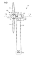
- FIG. 1 shows a wind turbine 100 according to an embodiment of the invention.
- the wind turbine 100 comprises a tower 120 which is mounted on a non-depicted fundament.
- a nacelle 122 On top of the tower 120 there is arranged a nacelle 122.
- a yaw angle adjustment device 121 which is capable of rotating the nacelle 122 around a non depicted vertical axis being aligned with the longitudinal extension of the tower 120.
- the yaw angle adjustment device 121 can also be used to adjust the yaw angle to a position, wherein the nacelle 122 is intentionally not perfectly aligned with the current wind direction.
- the wind turbine 100 further comprises a rotor 110 having three blades 114. In the perspective of Figure 1 only two blades 114 are visible.
- the rotor 110 is rotatable around a rotational axis 110a.
- the blades 114 which are mounted at a hub 112, extend radially with respect to the rotational axis 110a.
- a blade adjustment device 116 in order to adjust the blade pitch angle of each blade 114 by rotating the respective blade 114 around a non depicted axis being aligned substantially parallel with the longitudinal extension of the respective blade 114.
- the blade pitch angle of the respective blade 114 can be adjusted in such a manner that at least when the wind is not so strong a maximum wind power can be retrieved from the available wind power.
- the blade pitch angle can also be intentionally adjusted to a position, in which only a reduced wind power can be captured.
- a gear box 124 is used to convert the number of revolutions of the rotor 110 into a higher number of revolutions of a shaft 125, which is coupled in a known manner to an electromechanical transducer 140.
- the electromechanical transducer is a generator 140.
- the gear box 124 is optional and that the generator 140 may also be directly coupled to the rotor 110 by the shaft 125 without changing the numbers of revolutions.
- the wind turbine is a so caller Direct Drive (DD) wind turbine.
- a brake 126 is provided in order to stop the operation of the wind turbine 100 or to reduce the rotational speed of the rotor 110 for instance (a) in case of an emergency, (b) in case of too strong wind conditions which might harm the wind turbine 100, and/or (c) in case of an intentional saving of the consumed fatigue life time and/or the fatigue life time consumption rate of at least one structural component of the wind turbine 100.
- the wind turbine 100 further comprises a control system 153 for operating the wind turbine 100 in a highly efficient manner. Apart from controlling for instance the yaw angle adjustment device 121 the depicted control system 153 is also used for adjusting the blade pitch angle of the rotor blades 114 in an optimized manner.
- the generator 140 comprises a stator assembly 145 and a rotor assembly 150.
- the stator assembly 145 comprises a plurality of coils for generating electrical current in response to a time alternating magnetic flux.
- the rotor assembly 150 comprises a plurality of magnet component parts each comprising two different magnetic materials. The magnet component parts are arranged in rows being aligned with a longitudinal axis of the rotor assembly 150.
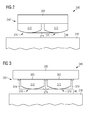
- FIG. 2 shows an electromechanical transducer 240 comprising a stator assembly 245 and a rotor assembly 250.
- An air gap ag is provided between the stator assembly 245 and the rotor assembly 250.
- the air gap ag is used for guiding a cooling fluid through the electromechanical transducer 240 in order to remove waste heat which during operation is generated by not depicted stator coils of the stator assembly 145.
- a plurality of magnet assemblies 270 is mounted to the support structure 260.
- the magnet assemblies 270 are arranged in a matrix like structure around a curved surface area of the support structure 260 having a basically cylindrical geometry. In Figure 2 for the sake of clarity only two of the magnet assemblies 270 are depicted.
- Each magnet assembly 270 comprises a magnet component 272 which is made from a permanent magnet material 272.
- the permanent magnet material is a material composition comprising a rare earth metal such as e.g. dysprosium.
- the magnet components 272 are spaced apart from each other such that a free space between the two neighboring magnet components 272 is provided.
- a thermal insulation structure 274 is provided, which covers a part of the surface of each magnet component 272. In order not to decrease the air gap ag the thermal insulation structure 274 is spatially limited to the above mentioned free space in between the two magnet components 272.
- the thermal insulation structure comprises a thermal insulation material 274.
- the thermal insulation material 274 may be any material which provides a good thermal insulation between a heated up cooling fluid traveling along the air gap ag and the permanent magnet material 272.
- the thermal insulation material 274 may comprise for instance a polyurethane foam, a phenol foam, a mineral wool, a glass wool, a silica lime sand brick and/or clay.
- Figure 3 shows an electromechanical transducer 340 comprising a rotor assembly 350 with a plurality of magnet assemblies 370 each being realized as a modular unit comprising a magnet component 272 and a thermal insulation material 374. Again, only two magnet assemblies 370 are depicted in Figure 3 .
- each magnet assembly 370 comprises not only one magnet component 272 but also one thermal insulation structure 374.
- each modular magnet assembly 370 comprises its own thermal insulation structure 374. This may provide the advantage that during assembling the rotor assembly 350 the thermal insulation structure 374 can be attached to the respective magnet component 272 before mounting the same to the support structure 260.
- each magnet assembly 370 is arranged at a back plate 362, which can be easily mounted to the support structure 260 for instance by means of dove tail connection.
- a T-shaped slot structure may be employed for mounting the back plates 362 to the support structure 260.
- FIG. 4 shows a rotor assembly 450 being equipped with modular magnet assemblies 470.
- Each modular magnet assembly 470 comprises an enclosure 476.
- the enclosure is arranged between the permanent magnet material 272 and the thermal insulation material 374.
- FIG. 5 shows a rotor assembly 550 being equipped with modular magnet assemblies 570.
- Each modular magnet assembly 570 comprises an enclosure 576 which surrounds both the permanent magnet material 272 and the thermal insulation material 374.
- FIG. 6 shows a rotor assembly 650 being equipped with modular magnet assemblies 670.
- Each modular magnet assembly 670 comprises an enclosure 576.
- a space between the enclosure 576 and the surface of the magnet component 272 is not filled with a thermal insulation material.
- this space is a free space 678 comprising a vacuum or at least a negative pressure.
Landscapes
- Engineering & Computer Science (AREA)
- Power Engineering (AREA)
- Permanent Field Magnets Of Synchronous Machinery (AREA)
- Connection Of Motors, Electrical Generators, Mechanical Devices, And The Like (AREA)
- Wind Motors (AREA)
Priority Applications (3)
| Application Number | Priority Date | Filing Date | Title |
|---|---|---|---|
| EP12161282.4A EP2645534B1 (de) | 2012-03-26 | 2012-03-26 | Magnetkomponente mit Wärmedämmstruktur, Rotoranordnung mit der Magnetkomponente, elektromechanischer Wandler und Windturbine |
| US13/850,359 US9490672B2 (en) | 2012-03-26 | 2013-03-26 | Magnet component with a thermal insulation structure, rotor assembly with such a magnet component, electromechanical transducer and wind turbine |
| CN201310099142.3A CN103368296B (zh) | 2012-03-26 | 2013-03-26 | 磁体部件、具有其的转子组件、机电换能器和风力涡轮机 |
Applications Claiming Priority (1)
| Application Number | Priority Date | Filing Date | Title |
|---|---|---|---|
| EP12161282.4A EP2645534B1 (de) | 2012-03-26 | 2012-03-26 | Magnetkomponente mit Wärmedämmstruktur, Rotoranordnung mit der Magnetkomponente, elektromechanischer Wandler und Windturbine |
Publications (2)
| Publication Number | Publication Date |
|---|---|
| EP2645534A1 true EP2645534A1 (de) | 2013-10-02 |
| EP2645534B1 EP2645534B1 (de) | 2018-01-31 |
Family
ID=45936918
Family Applications (1)
| Application Number | Title | Priority Date | Filing Date |
|---|---|---|---|
| EP12161282.4A Not-in-force EP2645534B1 (de) | 2012-03-26 | 2012-03-26 | Magnetkomponente mit Wärmedämmstruktur, Rotoranordnung mit der Magnetkomponente, elektromechanischer Wandler und Windturbine |
Country Status (3)
| Country | Link |
|---|---|
| US (1) | US9490672B2 (de) |
| EP (1) | EP2645534B1 (de) |
| CN (1) | CN103368296B (de) |
Cited By (4)
| Publication number | Priority date | Publication date | Assignee | Title |
|---|---|---|---|---|
| EP2887499A1 (de) * | 2013-12-18 | 2015-06-24 | Siemens Aktiengesellschaft | Statorisolierung für kalte Magneten |
| EP3285365A1 (de) * | 2016-08-19 | 2018-02-21 | Siemens Aktiengesellschaft | Reluktanzläufer |
| WO2018193095A1 (de) * | 2017-04-21 | 2018-10-25 | Efficient Energy Gmbh | Rotor für einen elektromotor mit wärmeabschirmender beschichtung und verfahren zur herstellung |
| EP4279857A3 (de) * | 2022-05-20 | 2024-03-20 | Rheinmetall Air Defence AG | Revolvergeschütz und verfahren zum betrieb eines revolvergeschützes |
Families Citing this family (5)
| Publication number | Priority date | Publication date | Assignee | Title |
|---|---|---|---|---|
| EP2143943A1 (de) * | 2008-07-09 | 2010-01-13 | Greenergy India Private Limited | Windturbine |
| EP2930825A1 (de) * | 2014-04-11 | 2015-10-14 | Siemens Aktiengesellschaft | Montage von Permanentmagneten auf einem Rotor einer elektrischen Maschine |
| EP3024126A1 (de) * | 2014-11-20 | 2016-05-25 | Siemens Aktiengesellschaft | Kühlanordnung |
| CN111326936B (zh) * | 2018-12-14 | 2023-08-18 | 富士康(昆山)电脑接插件有限公司 | 电连接器组件及其组装方法 |
| CN111834116B (zh) * | 2019-04-23 | 2025-03-28 | 西门子歌美飒可再生能源公司 | 制造具有减小的变形的烧结永磁体 |
Citations (4)
| Publication number | Priority date | Publication date | Assignee | Title |
|---|---|---|---|---|
| JP2005218274A (ja) * | 2004-02-02 | 2005-08-11 | Toyota Motor Corp | 回転電機の回転子 |
| WO2008046780A2 (de) * | 2006-10-17 | 2008-04-24 | Siemens Aktiengesellschaft | Magnetmodul für eine permanentmagneterregte elektrische maschine |
| JP2008125242A (ja) * | 2006-11-13 | 2008-05-29 | Meidensha Corp | 永久磁石式同期電動機 |
| WO2010109056A1 (en) * | 2009-03-25 | 2010-09-30 | Abb Oy | Permanent magnet electric machine and permanent magnet for an electric machine |
Family Cites Families (18)
| Publication number | Priority date | Publication date | Assignee | Title |
|---|---|---|---|---|
| US4678954A (en) * | 1986-03-05 | 1987-07-07 | Kabushiki Kaisha Toshiba | Rotor with permanent magnets having thermal expansion gaps |
| US5160911A (en) * | 1990-10-26 | 1992-11-03 | The United States Of America As Represented By The United States Department Of Energy | Toroidal constant-tension superconducting magnetic energy storage units |
| JPH0638414A (ja) * | 1992-07-14 | 1994-02-10 | Daido Steel Co Ltd | リング状磁石をそなえたロータ |
| US5801470A (en) * | 1996-12-19 | 1998-09-01 | General Electric Company | Rotors with retaining cylinders and reduced harmonic field effect losses |
| WO1998031497A1 (en) * | 1997-01-20 | 1998-07-23 | Kabushiki Kaisha Meidensha | Unified junction structure of rare-earth magnet and metal material and the jointing method |
| US6380833B1 (en) * | 1999-04-07 | 2002-04-30 | Saint-Gobain Performance Plastics Corporation | Encapsulated magnet assembly and method for making the same |
| JP2004350427A (ja) * | 2003-05-22 | 2004-12-09 | Denso Corp | 回転電機とその回転子 |
| JP2006304547A (ja) | 2005-04-22 | 2006-11-02 | Toyota Motor Corp | 永久磁石埋め込み式モータのロータとその製造方法 |
| US8018081B2 (en) | 2005-07-15 | 2011-09-13 | Southwest Windpower, Inc. | Wind turbine and method of manufacture |
| EP1985846A1 (de) | 2007-04-27 | 2008-10-29 | Greenergy India Private Limited | Windturbine |
| ES2353910T3 (es) * | 2007-05-09 | 2011-03-08 | Siemens Aktiengesellschaft | Procedimiento para la protección de imanes permanentes. |
| DK2109206T3 (da) * | 2008-04-10 | 2013-06-17 | Siemens Ag | Generator med en stator omfattende kølekanaler samt fremgangsmåde til køling af en lamineret stator af en generator |
| US7812495B2 (en) * | 2008-05-16 | 2010-10-12 | Honeywell International Inc. | Sleeve in end rings for permanent magnet rotor |
| CN101355277B (zh) | 2008-06-02 | 2010-09-15 | 北京中科三环高技术股份有限公司 | 大功率永磁电机的永磁磁极组件 |
| JP5468215B2 (ja) * | 2008-06-09 | 2014-04-09 | ダイキン工業株式会社 | 空気調和機及び空気調和機の製造方法 |
| JP5430204B2 (ja) * | 2009-04-01 | 2014-02-26 | キヤノン株式会社 | リニアモータおよびそれを用いたステージ装置、露光装置およびデバイス製造方法 |
| US8664819B2 (en) * | 2009-08-18 | 2014-03-04 | Northern Power Systems Utility Scale, Inc. | Method and apparatus for permanent magnet attachment in an electromechanical machine |
| DE102010023878A1 (de) | 2010-06-15 | 2011-12-22 | Daimler Ag | Rotor einer elektrischen Maschine |
-
2012
- 2012-03-26 EP EP12161282.4A patent/EP2645534B1/de not_active Not-in-force
-
2013
- 2013-03-26 CN CN201310099142.3A patent/CN103368296B/zh not_active Expired - Fee Related
- 2013-03-26 US US13/850,359 patent/US9490672B2/en not_active Expired - Fee Related
Patent Citations (4)
| Publication number | Priority date | Publication date | Assignee | Title |
|---|---|---|---|---|
| JP2005218274A (ja) * | 2004-02-02 | 2005-08-11 | Toyota Motor Corp | 回転電機の回転子 |
| WO2008046780A2 (de) * | 2006-10-17 | 2008-04-24 | Siemens Aktiengesellschaft | Magnetmodul für eine permanentmagneterregte elektrische maschine |
| JP2008125242A (ja) * | 2006-11-13 | 2008-05-29 | Meidensha Corp | 永久磁石式同期電動機 |
| WO2010109056A1 (en) * | 2009-03-25 | 2010-09-30 | Abb Oy | Permanent magnet electric machine and permanent magnet for an electric machine |
Cited By (5)
| Publication number | Priority date | Publication date | Assignee | Title |
|---|---|---|---|---|
| EP2887499A1 (de) * | 2013-12-18 | 2015-06-24 | Siemens Aktiengesellschaft | Statorisolierung für kalte Magneten |
| EP3285365A1 (de) * | 2016-08-19 | 2018-02-21 | Siemens Aktiengesellschaft | Reluktanzläufer |
| WO2018033410A1 (de) * | 2016-08-19 | 2018-02-22 | Siemens Aktiengesellschaft | Reluktanzläufer |
| WO2018193095A1 (de) * | 2017-04-21 | 2018-10-25 | Efficient Energy Gmbh | Rotor für einen elektromotor mit wärmeabschirmender beschichtung und verfahren zur herstellung |
| EP4279857A3 (de) * | 2022-05-20 | 2024-03-20 | Rheinmetall Air Defence AG | Revolvergeschütz und verfahren zum betrieb eines revolvergeschützes |
Also Published As
| Publication number | Publication date |
|---|---|
| US9490672B2 (en) | 2016-11-08 |
| CN103368296A (zh) | 2013-10-23 |
| EP2645534B1 (de) | 2018-01-31 |
| CN103368296B (zh) | 2017-03-01 |
| US20130249341A1 (en) | 2013-09-26 |
Similar Documents
| Publication | Publication Date | Title |
|---|---|---|
| US9490672B2 (en) | Magnet component with a thermal insulation structure, rotor assembly with such a magnet component, electromechanical transducer and wind turbine | |
| EP2348619B1 (de) | Magnetanordnung | |
| US8013464B2 (en) | Power generating system including modular wind turbine-generator assembly | |
| JP5218220B2 (ja) | ターボ分子ポンプ装置およびその制御装置 | |
| CN101761454B (zh) | 一种垂直轴磁悬浮风力发电机 | |
| US7982359B2 (en) | High efficiency salient pole machine and method of forming the same | |
| US20180145574A1 (en) | Axial Flux Machine | |
| US9515529B2 (en) | Method and apparatus for permanent magnet attachment in an electromechanical machine | |
| EP2555385B1 (de) | Dauermagnetanordnung mit Abdeckung aus Formkunststoff und Verfahren zum Schützen eines Dauermagneten | |
| US20140110948A1 (en) | Nd-fe-b permanent magnet without dysprosium, rotor assembly, electromechanical transducer, wind turbine | |
| EP2555383B1 (de) | Dauermagnetanordnung mit verschiebarer Befestigung und Verfahren zur Befestigung eines Dauermagneten auf einer Grundplatte | |
| EP2736154A1 (de) | Dauermagnetgenerator mit Doppelständer für eine Windturbine | |
| EP3638908B1 (de) | Flächenbündiges lüftersystem | |
| EP2887499B1 (de) | Statorisolierung für kalte Magneten | |
| CN102597504A (zh) | 开关盒布局 | |
| WO2014151496A1 (en) | Method and apparatus for permanent magnet attachment in an electromechanical machine | |
| CN102656781B (zh) | 风能发电机的磁极转子 | |
| EP2477311B1 (de) | Generator, insbesondere für eine Windturbine | |
| CA2754532A1 (en) | A generator, in particular for a wind turbine | |
| CN215733723U (zh) | 一种分层式辐射环磁铁转子结构 | |
| CN201319547Y (zh) | 电机的表面冷却元件 | |
| CN203289241U (zh) | 风冷散热电机 | |
| EP2605371B1 (de) | Magnetischer Komponententeil aus verschiedenen magnetischen Materialien | |
| CN207200509U (zh) | 一种碟式双气隙外转子无铁芯电机 | |
| JP2026008574A (ja) | アキシャル型コアレス低抵抗永久磁石モータ |
Legal Events
| Date | Code | Title | Description |
|---|---|---|---|
| PUAI | Public reference made under article 153(3) epc to a published international application that has entered the european phase |
Free format text: ORIGINAL CODE: 0009012 |
|
| AK | Designated contracting states |
Kind code of ref document: A1 Designated state(s): AL AT BE BG CH CY CZ DE DK EE ES FI FR GB GR HR HU IE IS IT LI LT LU LV MC MK MT NL NO PL PT RO RS SE SI SK SM TR |
|
| AX | Request for extension of the european patent |
Extension state: BA ME |
|
| 17P | Request for examination filed |
Effective date: 20131106 |
|
| RBV | Designated contracting states (corrected) |
Designated state(s): AL AT BE BG CH CY CZ DE DK EE ES FI FR GB GR HR HU IE IS IT LI LT LU LV MC MK MT NL NO PL PT RO RS SE SI SK SM TR |
|
| 17Q | First examination report despatched |
Effective date: 20170404 |
|
| RAP1 | Party data changed (applicant data changed or rights of an application transferred) |
Owner name: SIEMENS AKTIENGESELLSCHAFT |
|
| GRAP | Despatch of communication of intention to grant a patent |
Free format text: ORIGINAL CODE: EPIDOSNIGR1 |
|
| INTG | Intention to grant announced |
Effective date: 20170831 |
|
| GRAS | Grant fee paid |
Free format text: ORIGINAL CODE: EPIDOSNIGR3 |
|
| GRAA | (expected) grant |
Free format text: ORIGINAL CODE: 0009210 |
|
| AK | Designated contracting states |
Kind code of ref document: B1 Designated state(s): AL AT BE BG CH CY CZ DE DK EE ES FI FR GB GR HR HU IE IS IT LI LT LU LV MC MK MT NL NO PL PT RO RS SE SI SK SM TR |
|
| REG | Reference to a national code |
Ref country code: GB Ref legal event code: FG4D Ref country code: CH Ref legal event code: EP |
|
| REG | Reference to a national code |
Ref country code: AT Ref legal event code: REF Ref document number: 968195 Country of ref document: AT Kind code of ref document: T Effective date: 20180215 |
|
| REG | Reference to a national code |
Ref country code: IE Ref legal event code: FG4D |
|
| REG | Reference to a national code |
Ref country code: DE Ref legal event code: R096 Ref document number: 602012042520 Country of ref document: DE |
|
| REG | Reference to a national code |
Ref country code: FR Ref legal event code: PLFP Year of fee payment: 7 |
|
| REG | Reference to a national code |
Ref country code: NL Ref legal event code: MP Effective date: 20180131 |
|
| REG | Reference to a national code |
Ref country code: LT Ref legal event code: MG4D |
|
| REG | Reference to a national code |
Ref country code: AT Ref legal event code: MK05 Ref document number: 968195 Country of ref document: AT Kind code of ref document: T Effective date: 20180131 |
|
| PG25 | Lapsed in a contracting state [announced via postgrant information from national office to epo] |
Ref country code: NO Free format text: LAPSE BECAUSE OF FAILURE TO SUBMIT A TRANSLATION OF THE DESCRIPTION OR TO PAY THE FEE WITHIN THE PRESCRIBED TIME-LIMIT Effective date: 20180430 Ref country code: ES Free format text: LAPSE BECAUSE OF FAILURE TO SUBMIT A TRANSLATION OF THE DESCRIPTION OR TO PAY THE FEE WITHIN THE PRESCRIBED TIME-LIMIT Effective date: 20180131 Ref country code: NL Free format text: LAPSE BECAUSE OF FAILURE TO SUBMIT A TRANSLATION OF THE DESCRIPTION OR TO PAY THE FEE WITHIN THE PRESCRIBED TIME-LIMIT Effective date: 20180131 Ref country code: HR Free format text: LAPSE BECAUSE OF FAILURE TO SUBMIT A TRANSLATION OF THE DESCRIPTION OR TO PAY THE FEE WITHIN THE PRESCRIBED TIME-LIMIT Effective date: 20180131 Ref country code: LT Free format text: LAPSE BECAUSE OF FAILURE TO SUBMIT A TRANSLATION OF THE DESCRIPTION OR TO PAY THE FEE WITHIN THE PRESCRIBED TIME-LIMIT Effective date: 20180131 Ref country code: FI Free format text: LAPSE BECAUSE OF FAILURE TO SUBMIT A TRANSLATION OF THE DESCRIPTION OR TO PAY THE FEE WITHIN THE PRESCRIBED TIME-LIMIT Effective date: 20180131 |
|
| PG25 | Lapsed in a contracting state [announced via postgrant information from national office to epo] |
Ref country code: IS Free format text: LAPSE BECAUSE OF FAILURE TO SUBMIT A TRANSLATION OF THE DESCRIPTION OR TO PAY THE FEE WITHIN THE PRESCRIBED TIME-LIMIT Effective date: 20180531 Ref country code: GR Free format text: LAPSE BECAUSE OF FAILURE TO SUBMIT A TRANSLATION OF THE DESCRIPTION OR TO PAY THE FEE WITHIN THE PRESCRIBED TIME-LIMIT Effective date: 20180501 Ref country code: AT Free format text: LAPSE BECAUSE OF FAILURE TO SUBMIT A TRANSLATION OF THE DESCRIPTION OR TO PAY THE FEE WITHIN THE PRESCRIBED TIME-LIMIT Effective date: 20180131 Ref country code: SE Free format text: LAPSE BECAUSE OF FAILURE TO SUBMIT A TRANSLATION OF THE DESCRIPTION OR TO PAY THE FEE WITHIN THE PRESCRIBED TIME-LIMIT Effective date: 20180131 Ref country code: LV Free format text: LAPSE BECAUSE OF FAILURE TO SUBMIT A TRANSLATION OF THE DESCRIPTION OR TO PAY THE FEE WITHIN THE PRESCRIBED TIME-LIMIT Effective date: 20180131 Ref country code: RS Free format text: LAPSE BECAUSE OF FAILURE TO SUBMIT A TRANSLATION OF THE DESCRIPTION OR TO PAY THE FEE WITHIN THE PRESCRIBED TIME-LIMIT Effective date: 20180131 Ref country code: PL Free format text: LAPSE BECAUSE OF FAILURE TO SUBMIT A TRANSLATION OF THE DESCRIPTION OR TO PAY THE FEE WITHIN THE PRESCRIBED TIME-LIMIT Effective date: 20180131 Ref country code: BG Free format text: LAPSE BECAUSE OF FAILURE TO SUBMIT A TRANSLATION OF THE DESCRIPTION OR TO PAY THE FEE WITHIN THE PRESCRIBED TIME-LIMIT Effective date: 20180430 |
|
| PG25 | Lapsed in a contracting state [announced via postgrant information from national office to epo] |
Ref country code: RO Free format text: LAPSE BECAUSE OF FAILURE TO SUBMIT A TRANSLATION OF THE DESCRIPTION OR TO PAY THE FEE WITHIN THE PRESCRIBED TIME-LIMIT Effective date: 20180131 Ref country code: AL Free format text: LAPSE BECAUSE OF FAILURE TO SUBMIT A TRANSLATION OF THE DESCRIPTION OR TO PAY THE FEE WITHIN THE PRESCRIBED TIME-LIMIT Effective date: 20180131 Ref country code: EE Free format text: LAPSE BECAUSE OF FAILURE TO SUBMIT A TRANSLATION OF THE DESCRIPTION OR TO PAY THE FEE WITHIN THE PRESCRIBED TIME-LIMIT Effective date: 20180131 Ref country code: IT Free format text: LAPSE BECAUSE OF FAILURE TO SUBMIT A TRANSLATION OF THE DESCRIPTION OR TO PAY THE FEE WITHIN THE PRESCRIBED TIME-LIMIT Effective date: 20180131 |
|
| REG | Reference to a national code |
Ref country code: CH Ref legal event code: PL |
|
| REG | Reference to a national code |
Ref country code: DE Ref legal event code: R097 Ref document number: 602012042520 Country of ref document: DE |
|
| PG25 | Lapsed in a contracting state [announced via postgrant information from national office to epo] |
Ref country code: MC Free format text: LAPSE BECAUSE OF FAILURE TO SUBMIT A TRANSLATION OF THE DESCRIPTION OR TO PAY THE FEE WITHIN THE PRESCRIBED TIME-LIMIT Effective date: 20180131 Ref country code: DK Free format text: LAPSE BECAUSE OF FAILURE TO SUBMIT A TRANSLATION OF THE DESCRIPTION OR TO PAY THE FEE WITHIN THE PRESCRIBED TIME-LIMIT Effective date: 20180131 Ref country code: SM Free format text: LAPSE BECAUSE OF FAILURE TO SUBMIT A TRANSLATION OF THE DESCRIPTION OR TO PAY THE FEE WITHIN THE PRESCRIBED TIME-LIMIT Effective date: 20180131 Ref country code: SK Free format text: LAPSE BECAUSE OF FAILURE TO SUBMIT A TRANSLATION OF THE DESCRIPTION OR TO PAY THE FEE WITHIN THE PRESCRIBED TIME-LIMIT Effective date: 20180131 Ref country code: CZ Free format text: LAPSE BECAUSE OF FAILURE TO SUBMIT A TRANSLATION OF THE DESCRIPTION OR TO PAY THE FEE WITHIN THE PRESCRIBED TIME-LIMIT Effective date: 20180131 |
|
| PLBE | No opposition filed within time limit |
Free format text: ORIGINAL CODE: 0009261 |
|
| STAA | Information on the status of an ep patent application or granted ep patent |
Free format text: STATUS: NO OPPOSITION FILED WITHIN TIME LIMIT |
|
| REG | Reference to a national code |
Ref country code: BE Ref legal event code: MM Effective date: 20180331 |
|
| REG | Reference to a national code |
Ref country code: IE Ref legal event code: MM4A |
|
| PG25 | Lapsed in a contracting state [announced via postgrant information from national office to epo] |
Ref country code: LU Free format text: LAPSE BECAUSE OF NON-PAYMENT OF DUE FEES Effective date: 20180326 |
|
| 26N | No opposition filed |
Effective date: 20181102 |
|
| PG25 | Lapsed in a contracting state [announced via postgrant information from national office to epo] |
Ref country code: IE Free format text: LAPSE BECAUSE OF NON-PAYMENT OF DUE FEES Effective date: 20180326 |
|
| PG25 | Lapsed in a contracting state [announced via postgrant information from national office to epo] |
Ref country code: LI Free format text: LAPSE BECAUSE OF NON-PAYMENT OF DUE FEES Effective date: 20180331 Ref country code: CH Free format text: LAPSE BECAUSE OF NON-PAYMENT OF DUE FEES Effective date: 20180331 Ref country code: BE Free format text: LAPSE BECAUSE OF NON-PAYMENT OF DUE FEES Effective date: 20180331 Ref country code: SI Free format text: LAPSE BECAUSE OF FAILURE TO SUBMIT A TRANSLATION OF THE DESCRIPTION OR TO PAY THE FEE WITHIN THE PRESCRIBED TIME-LIMIT Effective date: 20180131 |
|
| REG | Reference to a national code |
Ref country code: DE Ref legal event code: R081 Ref document number: 602012042520 Country of ref document: DE Owner name: SIEMENS GAMESA RENEWABLE ENERGY A/S, DK Free format text: FORMER OWNER: SIEMENS AKTIENGESELLSCHAFT, 80333 MUENCHEN, DE |
|
| REG | Reference to a national code |
Ref country code: GB Ref legal event code: 732E Free format text: REGISTERED BETWEEN 20191128 AND 20191204 |
|
| PG25 | Lapsed in a contracting state [announced via postgrant information from national office to epo] |
Ref country code: MT Free format text: LAPSE BECAUSE OF NON-PAYMENT OF DUE FEES Effective date: 20180326 |
|
| PG25 | Lapsed in a contracting state [announced via postgrant information from national office to epo] |
Ref country code: TR Free format text: LAPSE BECAUSE OF FAILURE TO SUBMIT A TRANSLATION OF THE DESCRIPTION OR TO PAY THE FEE WITHIN THE PRESCRIBED TIME-LIMIT Effective date: 20180131 |
|
| PG25 | Lapsed in a contracting state [announced via postgrant information from national office to epo] |
Ref country code: PT Free format text: LAPSE BECAUSE OF FAILURE TO SUBMIT A TRANSLATION OF THE DESCRIPTION OR TO PAY THE FEE WITHIN THE PRESCRIBED TIME-LIMIT Effective date: 20180131 Ref country code: HU Free format text: LAPSE BECAUSE OF FAILURE TO SUBMIT A TRANSLATION OF THE DESCRIPTION OR TO PAY THE FEE WITHIN THE PRESCRIBED TIME-LIMIT; INVALID AB INITIO Effective date: 20120326 |
|
| PG25 | Lapsed in a contracting state [announced via postgrant information from national office to epo] |
Ref country code: CY Free format text: LAPSE BECAUSE OF FAILURE TO SUBMIT A TRANSLATION OF THE DESCRIPTION OR TO PAY THE FEE WITHIN THE PRESCRIBED TIME-LIMIT Effective date: 20180131 Ref country code: MK Free format text: LAPSE BECAUSE OF NON-PAYMENT OF DUE FEES Effective date: 20180131 |
|
| REG | Reference to a national code |
Ref country code: FR Ref legal event code: PLFP Year of fee payment: 12 |
|
| PGFP | Annual fee paid to national office [announced via postgrant information from national office to epo] |
Ref country code: FR Payment date: 20230320 Year of fee payment: 12 |
|
| PGFP | Annual fee paid to national office [announced via postgrant information from national office to epo] |
Ref country code: GB Payment date: 20230323 Year of fee payment: 12 Ref country code: DE Payment date: 20230320 Year of fee payment: 12 |
|
| REG | Reference to a national code |
Ref country code: DE Ref legal event code: R119 Ref document number: 602012042520 Country of ref document: DE |
|
| GBPC | Gb: european patent ceased through non-payment of renewal fee |
Effective date: 20240326 |
|
| PG25 | Lapsed in a contracting state [announced via postgrant information from national office to epo] |
Ref country code: DE Free format text: LAPSE BECAUSE OF NON-PAYMENT OF DUE FEES Effective date: 20241001 |
|
| PG25 | Lapsed in a contracting state [announced via postgrant information from national office to epo] |
Ref country code: GB Free format text: LAPSE BECAUSE OF NON-PAYMENT OF DUE FEES Effective date: 20240326 |
|
| PG25 | Lapsed in a contracting state [announced via postgrant information from national office to epo] |
Ref country code: FR Free format text: LAPSE BECAUSE OF NON-PAYMENT OF DUE FEES Effective date: 20240331 |
|
| PG25 | Lapsed in a contracting state [announced via postgrant information from national office to epo] |
Ref country code: GB Free format text: LAPSE BECAUSE OF NON-PAYMENT OF DUE FEES Effective date: 20240326 Ref country code: FR Free format text: LAPSE BECAUSE OF NON-PAYMENT OF DUE FEES Effective date: 20240331 Ref country code: DE Free format text: LAPSE BECAUSE OF NON-PAYMENT OF DUE FEES Effective date: 20241001 |