EP2645546A2 - Linearmotor-Kühlstruktur - Google Patents
Linearmotor-Kühlstruktur Download PDFInfo
- Publication number
- EP2645546A2 EP2645546A2 EP13001521.7A EP13001521A EP2645546A2 EP 2645546 A2 EP2645546 A2 EP 2645546A2 EP 13001521 A EP13001521 A EP 13001521A EP 2645546 A2 EP2645546 A2 EP 2645546A2
- Authority
- EP
- European Patent Office
- Prior art keywords
- flat plate
- section
- inflow
- cooling
- outflow
- Prior art date
- Legal status (The legal status is an assumption and is not a legal conclusion. Google has not performed a legal analysis and makes no representation as to the accuracy of the status listed.)
- Withdrawn
Links
Images




Classifications
-
- H—ELECTRICITY
- H02—GENERATION; CONVERSION OR DISTRIBUTION OF ELECTRIC POWER
- H02K—DYNAMO-ELECTRIC MACHINES
- H02K9/00—Arrangements for cooling or ventilating
- H02K9/10—Arrangements for cooling or ventilating by gaseous cooling medium flowing in closed circuit, a part of which is external to the machine casing
- H02K9/12—Arrangements for cooling or ventilating by gaseous cooling medium flowing in closed circuit, a part of which is external to the machine casing wherein the cooling medium circulates freely within the casing
-
- H—ELECTRICITY
- H02—GENERATION; CONVERSION OR DISTRIBUTION OF ELECTRIC POWER
- H02K—DYNAMO-ELECTRIC MACHINES
- H02K41/00—Propulsion systems in which a rigid body is moved along a path due to dynamo-electric interaction between the body and a magnetic field travelling along the path
- H02K41/02—Linear motors; Sectional motors
-
- H—ELECTRICITY
- H02—GENERATION; CONVERSION OR DISTRIBUTION OF ELECTRIC POWER
- H02K—DYNAMO-ELECTRIC MACHINES
- H02K1/00—Details of the magnetic circuit
- H02K1/06—Details of the magnetic circuit characterised by the shape, form or construction
- H02K1/22—Rotating parts of the magnetic circuit
- H02K1/32—Rotating parts of the magnetic circuit with channels or ducts for flow of cooling medium
-
- H—ELECTRICITY
- H02—GENERATION; CONVERSION OR DISTRIBUTION OF ELECTRIC POWER
- H02K—DYNAMO-ELECTRIC MACHINES
- H02K9/00—Arrangements for cooling or ventilating
- H02K9/22—Arrangements for cooling or ventilating by solid heat conducting material embedded in, or arranged in contact with, the stator or rotor, e.g. heat bridges
-
- H—ELECTRICITY
- H02—GENERATION; CONVERSION OR DISTRIBUTION OF ELECTRIC POWER
- H02K—DYNAMO-ELECTRIC MACHINES
- H02K9/00—Arrangements for cooling or ventilating
- H02K9/22—Arrangements for cooling or ventilating by solid heat conducting material embedded in, or arranged in contact with, the stator or rotor, e.g. heat bridges
- H02K9/227—Heat sinks
Definitions
- the present invention relates to a linear motor cooling structure for cooling a coil that constitutes a driving section of a linear motor.
- a linear motor cooling structure which includes a coil unit having an approximately I-shaped transverse cross-section and configured so as to cover a coil by a coil mold and further cover the coil mold by an inner wall, and an outer wall surrounding the outside of the coil unit and cools the coil that generates heat, by making a cooling medium flow between the inner wall and the outer wall of the coil unit has been known (refer to the related art, for example).
- a linear motor cooling structure for cooling a coil constituting a driving section of a linear motor, including: an inflow section into which cooling water flows; an outflow section from which the cooling water flows out; and a flat plate-shaped flat plate cooling section which includes an inflow opening for inflow of the cooling water from the inflow section, an outflow opening for outflow of the cooling water to the outflow section, and a flow path that makes the cooling water which has flowed in from the inflow opening flow through an inside thereof and flow out from the outflow opening, wherein the inflow section, the flat plate cooling section, and the outflow section are connected, and the inflow section and the inflow opening of the flat plate cooling section communicate with each other and also the outflow opening of the flat plate cooling section and the outflow section communicate with each other, whereby a cooling water flow path is configured, and the flat plate cooling section retains the coil in close contact with the coil.
- the linear motor cooling structure since the flat plate cooling section configured in a flat plate shape and having the flow path through which the cooling water flows, inside, retains the coil, the linear motor cooling structure has both a function to cool the coil and a function to retain the coil. For this reason, a holder or the like for retaining a coil becomes unnecessary, and thus the configuration of a cooling structure can be simplified. Then, since such a flat plate cooling section retains the coil in direct close contact with the coil, the coil can be efficiently cooled.
- one side of a flat plate face of the flat plate cooling section and the inflow section may overlap in a thickness direction, whereby the inflow opening of the flat plate cooling section and the inflow section communicate with each other, and the other side of the flat plate face of the flat plate cooling section and the outflow section may overlap in the thickness direction, whereby the outflow opening of the flat plate cooling section and the outflow section communicate with each other.
- the configuration of the cooling structure can be further simplified.
- the flat plate cooling section is provided by two and the two flat plate cooling sections pinch and retain the coil, the configuration of a cooling structure can be further simplified.
- the flat plate cooling section may be provided in plural, the flat plate cooling sections may be made to be able to be connected to each other, and when the plurality of flat plate cooling sections is connected, the outflow opening of the flat plate cooling section on one side and the inflow opening of the flat plate cooling section on the other side may communicate with each other.
- a cooling structure extending a direction in which, for example, a plurality of coils is arranged can be easily configured by connecting the plurality of flat plate cooling sections and also connecting the inflow section to the flat plate cooling section of an end on one side and the outflow section to the flat plate cooling section of an end on the other side. Therefore, it is possible to easily configure a cooling structure in accordance with the coils.
- Fig. 1 is a perspective view showing a linear motor cooling structure according to a first embodiment of the present invention
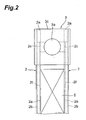
- Fig. 2 is a plan view for describing flow paths of a flat plate cooling section and an inflow section in Fig. 1
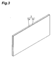
- Fig. 3 is a perspective view showing the flat plate cooling section on the front side in Fig. 1
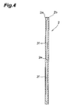
- Fig. 4 is a transverse cross-sectional view showing the flat plate cooling section of Fig. 3
- Fig. 5 is a perspective view when a first flat plate member in Fig. 3 is viewed from the back side
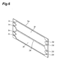
- Fig. 6 is a perspective view when the first flat plate member in Fig. 3 is viewed from the front side.
- a linear motor with the linear motor cooling structure according to this embodiment applied thereto includes coils 5 (refer to Fig. 1 ), each of which is wound so as to form a rectangular plate shape and which are arranged in a predetermined direction, and an N-pole magnet (not shown) and an S-pole magnet (not shown) which are alternately continuously arranged to face the coils 5, and is made such that the coils 5 are energized, thereby generating electromagnetic forces between the N-pole magnet and the S-pole magnet, and the coils 5 are moved with a linear motor cooling structure 100 for cooling the coils 5, by the electromagnetic forces.
- three coils 5 form a UVW three-phase.
- the linear motor cooling structure 100 is a cooling structure for the coil 5, which suppresses an increase in the temperature of the coil 5 constituting a driving section of the linear motor, as described above.
- the linear motor cooling structure 100 in the linear motor cooling structure 100, two flat plate cooling sections 2 which pinch the coil 5 from both sides are provided. Further, the linear motor cooling structure 100 includes an inflow section 3, into which cooling water flows and which is provided on one end side in an arrangement direction of the coils 5, and an outflow section 4, from which the cooling water flows out and which is provided on the other end side, in addition to the flat plate cooling section 2 and the coil 5.
- the flat plate cooling section 2 has a structure in which a first flat plate member 2a and a second flat plate member 2b which have rectangular shapes are laminated, as shown in Figs. 3 and 4 .
- a material of each of the first flat plate member 2a and the second flat plate member 2b is, for example, metal, ceramic, or resin.
- the first flat plate member 2a has four inflow openings 2c which are formed in a circular shape to penetrate a flat plate face on one end side in a longitudinal direction thereof and four outflow openings 2d which are formed in a circular shape to penetrate the flat plate face on the other end side in the longitudinal direction thereof, as shown in Figs. 5 and 6 .
- the inflow opening 2c and the outflow opening 2d are formed as through-holes penetrating in a direction perpendicular to a face of the first flat plate member 2a.
- the inflow openings 2c and the outflow openings 2d are vertically arranged.
- the first flat plate member 2a has two concave portions (flow path) 2f which are formed to be recessed with respect to the flat plate face thereof and provided in a pair up and down, and a rib portion 2e which becomes a partition portion partitioning the concave portions 2f arranged up and down on the front side (the front side of Fig. 6 ).
- the concave portion 2f is formed so as to extend from the inflow opening 2c to the outflow opening 2d and such that a width in the vertical direction becomes wide, and communicates with two inflow openings 2c and 2c on the upper side or the lower side, which are arranged up and down on one end side, and the other end side thereof communicates with two outflow openings 2d and 2d on the upper side or the lower s ide, which are arranged up and down to correspond to the inflow openings 2c and 2c.
- Each of the inflow openings 2c and 2c on one end side of the concave portion 2f is made such that a width in the vertical direction is smaller than the width in the vertical direction of the concave portion 2f, and each of the outflow openings 2d and 2d on the other end side of the concave portion 2f is also made such that a width in the vertical direction is smaller than the width in the vertical direction of the concave portion 2f.
- the rib portion 2e between the upper and lower concave portions 2f and 2f is formed to extend in a direction toward the outflow opening 2d from the inflow opening 2c and becomes flush with (has a face having the same height as) the flat plate face in which the concave portion 2f is not provided, thereby being made to be high with respect to the concave portion 2f.
- the second flat plate member 2b is a flat plate having the same size as the first flat plate member 2a, as shown in Figs. 3 and 4 .
- a flat plate face of the second flat plate member 2b and the face on the side having the concave portion 2f of the first flat plate member 2a are overlapped and joined, whereby the concave portion 2f is covered, thereby becoming an internal space of the flat plate cooling section 2, and the internal space becomes a cooling water flow path which extends in the longitudinal directions of the flat plate members 2a and 2b.
- a flow path of the flat plate cooling section 2 is formed by making the first flat plate member 2a itself be a non-flat plate shape (a shape having the concave portion 2f).
- Joining of the first flat plate member 2a and the second flat plate member 2b is, for example, diffusion joining or thermal joining and the flat plate cooling section 2 has a two-layer laminated structure.
- the inflow section 3 has an upper portion 3b formed in a rectangular parallelepiped shape and a lower portion 3c formed in a rectangular parallelepiped shape and formed so as to extend downward from the lower surface of the upper portion 3b and become small by narrowing the upper portion 3b from both sides in a thickness direction (the left-and-right direction in Fig. 2 ), as shown in Figs. 1 and 2 .
- an inflow opening 3a for inflow of the cooling water which is opened in the upper surface and extends downward, is provided.
- the lower portion 3c of the inflow section 3 has the same thickness as the thickness of the coil 5 and is made so as to be pinched by the two flat plate cooling sections 2.
- the inflow section 3 is installed by being connected to the flat plate cooling sections 2 by bolt fastening, for example, with an O-ring interposed between the flat plate cooling sections 2 and the inflow section 3, in a state where the lower portion 3c of the inflow section 3 is pinched by the two flat plate cooling sections 2 and the lower surface of the upper portion 3b of the inflow section 3 comes into contact with the upper surfaces of the flat plate cooling sections 2. Further, in the side surfaces of the lower portion 3c of the inflow section 3, a plurality of through-holes for communication with the respective inflow openings 2c is formed, and when the inflow section 3 is installed at the flat plate cooling section 2, the through-holes communicate with the inflow openings 2c of the flat plate cooling section 2, as shown in Fig. 2 .
- the inflow section 3 has a plurality of through-holes communicating with a plurality of inflow openings 2c. Further, the inflow section 3 is provided with the inflow opening 3a for introducing the cooling water into the inflow section 3 itself and has a branch structure for introducing the cooling water introduced into the inside, into the plurality of through-holes.
- the outflow section 4 has an upper portion 4b formed in a rectangular parallelepiped shape and a lower portion 4c formed in a rectangular parallelepiped shape and formed so as to extend downward from the lower surface of the upper portion 4b and become small by narrowing the upper portion 4b from both sides in a thickness direction, as shown in Fig. 1 , similarly to the inflow section 3.
- an outflow opening 4a for outflow of the cooling water which is opened in the upper surface and extends downward, is provided.
- the outflow section 4 is made so as to be installed at the flat plate cooling section 2 by pinching the lower portion 4c thereof by the two flat plate cooling sections 2, similarly to the inflow section 3.
- a plurality of through-holes for communication with the outflow openings 2d are formed, and when the outflow section 4 is installed at the flat plate cooling section 2, the through-holes communicate with the outflow openings 2d of the flat plate cooling section 2.
- the outflow section 4 has a plurality of through-holes that communicates with a plurality of outflow openings 2d. Further, the outflow section 4 is provided with the outflow opening 4a for discharging the cooling water from the outflow section 4 itself and has a confluence structure which makes the cooling water flowing into the plurality of through-holes join together and leads the cooling water to the outflow opening 4a.
- the cooling water flows in from the inflow opening 3a in a state where the outflow section 4 and the inflow section 3 are installed with respect to the flat plate cooling section 2, the cooling water passes through the inflow openings 2c and 2c of the flat plate cooling section 2, flows through the concave portions 2f and 2f that are the internal spaces, and passes through the outflow openings 2d and 2d, and then flows out from the outflow opening 4a of the outflow section 4 to the outside.
- the coil 5 which is pinched by the flat plate cooling sections 2 constituting the linear motor cooling structure 100 is retained in close contact with the flat plate cooling sections 2 by adhesion, a frictional force, or joining, here.
- the linear motor cooling structure 100 since the flat plate cooling sections 2 each configured in a flat plate shape and having the flow path 2f through which the cooling water flows, inside, retain the coil 5, the linear motor cooling structure 100 has both a function to cool the coil 5 and a function to retain the coil 5, and thus a holder or the like for retaining a coil becomes unnecessary. Therefore, the configuration of a cooling structure can be simplified. Then, since the flat plate cooling sections 2 retain the coil 5 in direct close contact with the coil 5, the coil 5 can be efficiently cooled.
- the flat plate face of the flat plate cooling section 2 and the inflow section 3 overlap in the thickness direction (the lower portion 3c of the inflow section 3 is pinched by the two flat plate cooling sections 2 in the thickness direction), whereby the inflow opening 2c and the inflow section 3 communicate with each other, and the flat plate face of the flat plate cooling section 2 and the outflow section 4 overlap in the thickness direction (the lower portion 4c of the outflow section 4 is pinched by the two flat plate cooling sections 2 in the thickness direction), whereby the outflow opening 2d and the outflow section 4 communicate with each other. Therefore, a cooling structure is completed only by overlapping the inflow section 3 and the outflow section 4 with the flat plate face of the flat plate cooling section 2, and thus the configuration of a cooling structure can be further simplified.
- the flat plate cooling section 2 is provided by two and the two flat plate cooling sections 2 pinch and retain the coil 5, the configuration of a cooling structure can be further simplified.
- the flat plate cooling section 2 having a flow path through which the cooling water flows, inside is configured only by overlapping the first and second flat plate members 2a and 2b, the configuration of a cooling structure can be further simplified. Then, since such a flat plate cooling section performs cooling in direct close contact with the coil, the coil can be efficiently cooled.
- the first flat plate member 2a has the inflow openings 2c and the outflow openings 2d which respectively are two or more (here, two) with respect to a single flow path 2f, the cooling water more evenly flows through the inside (the concave portion 2f) of the flat plate cooling section 2, compared to a case where each of an inflow opening and an outflow opening is one, and thus the coil 5 can be more efficiently cooled.
- cooling water flows so as to diffuse to spread from the inflow opening 2c to a longitudinal central portion of the flow path 2f and then converge toward the outflow opening 2d.
- the cooling water does not evenly flow, and as a result, a biased temperature distribution is made.
- the flow path 2f is formed in plural (here, two) and the flow paths 2f are separated with respect to an adjacent flow path through the rib portion 2e, in a state where the width in the vertical direction of a cooling water flow path is narrowed by the rib portion 2e, compared to a case where there is no rib portion 2e and a single flow path is provided, the cooling water efficiently flows in a direction extending from the inflow opening 2c to the outflow opening 2d in each flow path, and thus the coil 5 can be even more efficiently cooled.
- the flat plate cooling section 2 has high withstanding pressure and deformation with an increase in internal pressure can be suppressed.
- the inflow section 3 has, at the lower portion 3c thereof, a plurality of through-holes communicating with the respective inflow openings 2c of the flat plate cooling section 2 and the cooling water which has flowed in from the inflow opening 3a branches and flows into each inflow opening 2c,
- the inflow section 3 since the inflow section 3 has a branch structure like a so-called manifold, it is possible to make the cooling water equally flow into the respective inflow openings 2c, and thus the inflow section 3 has a structure suitable for a case where a plurality of inflow openings 2c is provided.
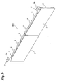
- the linear motor cooling structure 200 according to the second embodiment is different from the linear motor cooling structure 100 according to the first embodiment in that the coils 5 facing each other are provided in a set and the flat plate cooling section 2 is interposed between the coils 5 facing each other, thereby retaining the coils 5 on both sides.
- the linear motor cooling structure 200 according to the second embodiment is the same as the linear motor cooling structure 100 according to the first embodiment except for the above-described point, and the cooling water for cooling the coil 5 flows in from the inflow opening 3a of the inflow section 3, flows into the concave portion 2f that is an internal space through the inflow opening 2c of the flat plate cooling section 2, passes through the outflow opening 2d, and then flows out from the outflow opening 4a of the outflow section 4 to the outside.
- the linear motor cooling structure 300 according to the third embodiment is different from the linear motor cooling structures 100 and 200 according to the first and second embodiments in that the flat plate cooling section 2 retains the coil 5 by bringing the coil 5 into close contact with one face of the flat plate faces thereof.
- the linear motor cooling structure 300 according to the third embodiment is the same as the linear motor cooling structures 100 and 200 according to the first and second embodiments except for the above-described point, and the flow of the cooling water is the same as that in the second embodiment.
- the configuration of a cooling structure can be simplified, similarly to the first and second embodiments.
- the linear motor cooling structure 400 according to the fourth embodiment is different from the linear motor cooling structure 100 according to the first embodiment in that the flat plate cooling section 2 is provided in plural in a longitudinal direction and the flat plate cooling sections 2 are made capable of being connected to each other.
- the flat plate cooling sections 2 are made capable of being connected to each other in a direction in which the coils 5 are arranged, and, for example, a downstream end (a right end) of the flat plate cooling section 2 on the upstream side (the left side) having the inflow section 3 and an upstream end (a left end) of the flat plate cooling section 2 on the downstream side (the right side) having the outflow section 4 are brought into contact with each other and connected, whereby the outflow opening 2d of the flat plate cooling section 2 on the upstream side and the inflow opening 2c of the flat plate cooling section 2 on the downstream side are made to communicate with each other.
- the cooling water which has flowed in from the inflow opening 3a of the inflow section 3 flows into the concave portion 2f and the outflow opening 2d through the inflow opening 2c of the flat plate cooling section 2 on the upstream side, flows into the concave portion 2f and the outflow opening 2d through the inflow opening 2c of the flat plate cooling section 2 on the downstream side, and then flows out from the outflow opening 4a of the outflow section 4.
- a cooling structure extending in a direction in which a plurality of coils 5 is arranged can be easily configured by connecting a plurality of flat plate cooling sections 2 and also connecting the inflow section 3 to the flat plate cooling section 2 of an end on one side and the outflow section 4 to the flat plate cooling section 2 of an end on the other side. Therefore, it is possible to easily configure a cooling structure in accordance with the coil. In addition, such a connection configuration can also be applied to the second and third embodiments.
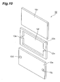
- the linear motor cooling structure according to the fifth embodiment is different from the linear motor cooling structure 100 according to the first embodiment in that in place of the flat plate cooling section 2 which includes the first flat plate member 2a and the second flat plate member 2b, a flat plate cooling section 12 having three rectangular flat plate members, a first flat plate member 12a, a second flat plate member 12b, and a third flat plate member 12c, is used.
- the first, second, and third flat plate members 12a, 12b, and 12c have the same size.
- the first flat plate member 12a has an inflow opening 12d which is formed to penetrate a flat place face on one end side in a longitudinal direction thereof, and an outflow opening 12g which is formed to penetrate the flat place face on the other end side in the longitudinal direction.
- the second flat plate member 12b has an opening 12f which is formed to penetrate a flat place face thereof in a rectangular shape, and concave portions 12e and 12e which are respectively formed so as to be further recessed from both left and right end portions of the opening 12f to both left and right end sides.
- the concave portions 12e and 12e are provided at positions corresponding to the inflow opening 12d and the outflow opening 12g. If the flat plate face of the first flat plate member 12a and the flat plate face of the second flat plate member 12b are overlapped, the inflow opening 12d and the concave portion 12e on the left side communicate with each other and the outflow opening 12g and the concave portion 12e on the right side communicate with each other.
- the opening 12f is interposed between the first flat plate member 12a and the third flat plate member 12c, and thus both sides thereof are blocked, whereby an internal space of the flat plate cooling section 12 is formed, and the internal space becomes a cooling water flow path.
- the second flat plate member 12b having a non-flat plate shape (having the opening 12f) is interposed between the first and third flat plate members 12a and 12c so as to form a portion of overlapping members, whereby a flow path of the flat plate cooling section 12 is formed.
- the flat plate cooling section 12 has a three-layer laminated structure.
- the flat plate cooling section 12 is made so as to be able to install the inflow section 3 and the outflow section 4 thereat, similarly to the flat plate cooling section 2 in the first to fourth embodiments, and when the inflow section 3 is installed, the inflow opening 3a and the inflow opening 12d communicate with each other, and when the outflow section 4 is installed, the outflow opening 4a and the outflow opening 12g communicate with each other. Accordingly, if the cooling water flows in from the inflow opening 3a of the inflow section 3, the cooling water flows from the inflow opening 12d into the opening 12f, flows out into the outflow section 4 through the outflow opening 12g, and then flows out to the outside.
- the flat plate cooling section 12 constituting the linear motor cooling structure according to the fifth embodiment can be used in place of the flat plate cooling section 2 in the first to fourth embodiments.
- the flat plate cooling section 12 has the concave portions 12e and 12e which are respectively formed to be further recessed from both left and right end portions of the opening 12 f to both left and right end sides and is made such that the inflow opening 12d and the (inflow side) concave portion 12e on the left side (of one end) communicate with each other and the outflow opening 12g and the (outflow side) concave portion 12e on the right side (of the other end) communicate with each other, the cooling water which has flowed from the inflow opening 12d into the (inflow side) concave portion 12e on the left side is blocked by wall portions of the second flat plate member 12b, which are present at the top and bottom and the left side of the concave portion 12e, and more suitably flows in a direction toward the outflow opening 12g.
- the cooling water which has flowed to the (outflow side) concave portion 12e on the right side is blocked by wall portions of the second flat plate member 12b, which are present at the top and bottom and the right side of the concave portion 12e, and more suitably enters the outflow opening 12g.
- the flat plate cooling section 12 since the flat plate cooling section 12 has wall portions at portions which are portions around the inflow opening 12d and the outflow opening 12g and at portions other than a portion that is connected to the flow path, the cooling water can efficiently flow in a direction extending from the inflow opening 12d to the outflow opening 12g and efficiently cool the coil 5.
- the operation and effects by the wall portions are also likewise generated in the flat plate cooling section 2 in the first to fourth embodiments.
- the concave portions 12e and 12e may be omitted, and, for example, by lengthening the length in a longitudinal direction of the opening 12f (lengthening the length of the opening 12f so as to extend to end edges of the concave portions 12e and 12e), a configuration may also be made such that the inflow opening 12d and the opening 12f communicate with each other and the outflow opening 12g and the opening 12f communicate with each other.
- a case where the concave portion 12e is provided is advantageous in terms of obtaining the above-described effect and enhancing rigidity.
- a configuration is made such that the inflow opening 2c of the flat plate cooling section 2 and the inflow section 3 communicate with each other by overlapping the flat plate face of the flat plate cooling section 2 and the inflow section 3 in the thickness direction.
- a configuration may also be made such that, for example, a side end face of the flat plate cooling section 2 and the inflow section 3 communicate with each other by overlapping the side end face of the flat plate cooling section 2 and the inflow section 3. The same applies to the relationship between the flat plate cooling section 2 and the outflow section 4.
- each of the inflow opening 2c and the outflow opening 2d is provided by four to be arranged up and down, two concave portions 2f are provided in a pair up and down, one end side of the concave portion 2f communicates with two inflow openings 2c, and the other end side of the concave portion 2f communicates with two outflow openings 2d.
- the number of inflow openings 2c, outflow openings 2d, and concave portions 2f or an aspect of a cooling water flow path is not limited to the above description.
- the rib portion 2e partitioning the concave portions 2f it is possible to change the number, the shape, or the like thereof.
- inflow section 3 and the outflow section 4 functions of introduction and lead-out of the cooling water to and from the flat plate cooling section 2 are given.
- a so-called yoke the combination of a magnet and a magnetic body
- introduction of cooling water for cooling the coil be performed from above.
- introduction and lead-out of the cooling water can be performed from inflow and outflow places provided on the upper face sides of an inflow section and an outflow section.
- the inflow section and the outflow section have flow path shapes changing an inflow direction of the cooling water, whereby it can be achieved.
- it may be performed by the embodiment as shown particularly in Figs. 2 and 6 .
- the linear motor in which the coil side moves has been described as an example.
- the present invention may also be applied to a linear motor in which the magnet side moves.
Landscapes
- Engineering & Computer Science (AREA)
- Power Engineering (AREA)
- Physics & Mathematics (AREA)
- Chemical & Material Sciences (AREA)
- Combustion & Propulsion (AREA)
- Electromagnetism (AREA)
- Motor Or Generator Cooling System (AREA)
- Linear Motors (AREA)
Applications Claiming Priority (1)
| Application Number | Priority Date | Filing Date | Title |
|---|---|---|---|
| JP2012071555A JP5859360B2 (ja) | 2012-03-27 | 2012-03-27 | リニアモータ冷却構造 |
Publications (2)
| Publication Number | Publication Date |
|---|---|
| EP2645546A2 true EP2645546A2 (de) | 2013-10-02 |
| EP2645546A3 EP2645546A3 (de) | 2017-05-31 |
Family
ID=48095488
Family Applications (1)
| Application Number | Title | Priority Date | Filing Date |
|---|---|---|---|
| EP13001521.7A Withdrawn EP2645546A3 (de) | 2012-03-27 | 2013-03-25 | Linearmotor-Kühlstruktur |
Country Status (5)
| Country | Link |
|---|---|
| US (1) | US9325223B2 (de) |
| EP (1) | EP2645546A3 (de) |
| JP (1) | JP5859360B2 (de) |
| KR (1) | KR101535330B1 (de) |
| TW (1) | TWI499172B (de) |
Cited By (1)
| Publication number | Priority date | Publication date | Assignee | Title |
|---|---|---|---|---|
| EP3264575A1 (de) * | 2016-06-28 | 2018-01-03 | Etel S. A.. | Kühlungseinrichtung für den primärteil eines eisenlosen linearmotors |
Families Citing this family (7)
| Publication number | Priority date | Publication date | Assignee | Title |
|---|---|---|---|---|
| EP2808986B1 (de) * | 2013-05-27 | 2016-03-09 | Etel S. A.. | Kühlkörper für einen Linearmotor |
| WO2016106140A1 (en) * | 2014-12-22 | 2016-06-30 | Otis Elevator Company | Mounting assembly for elevator linear propulsion system |
| EP3324521B1 (de) * | 2016-11-16 | 2020-04-15 | Etel S. A.. | Kühlplatte für einen linearmotor |
| EP3422537B1 (de) * | 2017-06-30 | 2020-05-20 | Etel S.A. | Spulenanordnung und gehäusemodulset für eine spulenanordnung eines elektromotors |
| JP7402102B2 (ja) * | 2020-03-30 | 2023-12-20 | 住友重機械工業株式会社 | リニアモータの冷却ユニット、リニアモータ、リニアモータの冷却ユニットの製造方法 |
| JP7349540B1 (ja) * | 2022-07-28 | 2023-09-22 | 株式会社ソディック | 電機子、冷却ユニットおよびリニアモータ |
| KR102809449B1 (ko) * | 2023-11-29 | 2025-05-19 | 하이윈 마이크로시스템 코포레이션 | 선형 모터의 냉각 모듈 |
Family Cites Families (33)
| Publication number | Priority date | Publication date | Assignee | Title |
|---|---|---|---|---|
| JPS4819744B1 (de) * | 1967-02-07 | 1973-06-15 | ||
| US4315300A (en) * | 1979-01-29 | 1982-02-09 | The United States Of America As Represented By The Secretary Of The Navy | Cooling arrangement for plug-in module assembly |
| US4306616A (en) * | 1980-02-04 | 1981-12-22 | Duke Manufacturing Co. | Refrigerated shelf for a food display counter |
| US4393565A (en) * | 1980-05-09 | 1983-07-19 | Wilson Welding Company, Inc. | Method of making a water-cooled electrode holder |
| US4342878A (en) * | 1980-05-09 | 1982-08-03 | Wilson Welding Company, Inc. | Water-cooled electrode holder |
| US4401870A (en) * | 1981-11-10 | 1983-08-30 | Hydro-Quebec | Modular suction-gas-cooled magnetic blast circuit breaker |
| US4397234A (en) * | 1981-12-30 | 1983-08-09 | International Business Machines Corporation | Electromagnetic print hammer coil assembly |
| US5723917A (en) * | 1994-11-30 | 1998-03-03 | Anorad Corporation | Flat linear motor |
| US5864187A (en) * | 1997-03-27 | 1999-01-26 | Ford Global Technologies, Inc. | Fully enclosed linear motor armature |
| JP3658980B2 (ja) * | 1998-03-06 | 2005-06-15 | 豊田工機株式会社 | 電磁コイルの冷却装置及び同装置を備えたリニアモータ |
| JP3643273B2 (ja) * | 1999-10-28 | 2005-04-27 | 株式会社ソディック | リニアモータのコイル装置およびその製造方法 |
| JP3832556B2 (ja) * | 2000-02-25 | 2006-10-11 | 株式会社安川電機 | キャンド・リニアモータ |
| JP2002010618A (ja) * | 2000-06-16 | 2002-01-11 | Canon Inc | リニアモータ、及びこれを有するステージ装置、露光装置 |
| KR100432243B1 (ko) * | 2001-07-06 | 2004-05-22 | 삼익Lms주식회사 | 방열구조를 가진 리니어모터 |
| JP4038652B2 (ja) * | 2001-11-30 | 2008-01-30 | 株式会社安川電機 | リニアモータ電機子およびリニアモータ |
| JP3809381B2 (ja) * | 2002-01-28 | 2006-08-16 | キヤノン株式会社 | リニアモータ、ステージ装置、露光装置及びデバイス製造方法 |
| US6806594B2 (en) * | 2002-02-20 | 2004-10-19 | Sumitomo Heavy Industries, Ltd. | Coil unit for linear motor |
| JP2003333822A (ja) * | 2002-05-13 | 2003-11-21 | Canon Inc | リニアモータ、これを有するステージ装置及び露光装置 |
| WO2004091079A1 (ja) * | 2003-04-07 | 2004-10-21 | Kabushiki Kaisha Yaskawa Denki | キャンド・リニアモータ電機子およびキャンド・リニアモータ |
| US6956308B2 (en) * | 2003-07-15 | 2005-10-18 | Nikon Corporation | Dual flow circulation system for a mover |
| US7235902B2 (en) * | 2004-07-21 | 2007-06-26 | Newport Corporation | Cooling system for linear motors |
| JP2008527965A (ja) * | 2005-01-18 | 2008-07-24 | コーニンクレッカ フィリップス エレクトロニクス エヌ ヴィ | 電気モータ用コイルアセンブリ |
| JP4524803B2 (ja) * | 2005-10-18 | 2010-08-18 | 株式会社安川電機 | キャンド・リニアモータ電機子およびキャンド・リニアモータ |
| TWM291649U (en) * | 2006-01-02 | 2006-06-01 | Hiwin Mikrosystem Corp | A thermolysis device for linear motors |
| DE102006012736A1 (de) * | 2006-03-17 | 2007-09-20 | Siemens Ag | Elektrische Maschine |
| US20070257563A1 (en) * | 2006-05-06 | 2007-11-08 | Lieh-Feng Huang | Heat Dissipating Arrangement for a Linear Motor |
| JP4819744B2 (ja) | 2007-05-08 | 2011-11-24 | 住友重機械工業株式会社 | リニアモータ冷却構造 |
| CN101657956B (zh) * | 2007-06-13 | 2013-01-16 | 株式会社安川电机 | 密封直线电动机电枢以及密封直线电动机 |
| JP2009060773A (ja) * | 2007-09-04 | 2009-03-19 | Canon Inc | 駆動装置およびそれを用いた平面モータおよびそれを用いた露光装置 |
| JP5369265B2 (ja) * | 2009-01-06 | 2013-12-18 | 東芝機械株式会社 | リニアモータ及びリニア移動ステージ装置 |
| JP5598757B2 (ja) * | 2010-01-26 | 2014-10-01 | 株式会社安川電機 | 冷媒冷却リニアモータ |
| JP5582415B2 (ja) * | 2010-08-27 | 2014-09-03 | 株式会社安川電機 | リニアモータ電機子およびそれを備えたリニアモータ |
| US20120062866A1 (en) * | 2010-09-03 | 2012-03-15 | Nikon Corporation | Microchannel-cooled coils of electromagnetic actuators exhibiting reduced eddy-current drag |
-
2012
- 2012-03-27 JP JP2012071555A patent/JP5859360B2/ja not_active Expired - Fee Related
-
2013
- 2013-03-08 TW TW102108224A patent/TWI499172B/zh not_active IP Right Cessation
- 2013-03-25 EP EP13001521.7A patent/EP2645546A3/de not_active Withdrawn
- 2013-03-26 US US13/850,444 patent/US9325223B2/en not_active Expired - Fee Related
- 2013-03-26 KR KR1020130032256A patent/KR101535330B1/ko not_active Expired - Fee Related
Non-Patent Citations (1)
| Title |
|---|
| None |
Cited By (2)
| Publication number | Priority date | Publication date | Assignee | Title |
|---|---|---|---|---|
| EP3264575A1 (de) * | 2016-06-28 | 2018-01-03 | Etel S. A.. | Kühlungseinrichtung für den primärteil eines eisenlosen linearmotors |
| US10797577B2 (en) | 2016-06-28 | 2020-10-06 | Etel S.A. | Primary element of an ironless linear motor |
Also Published As
| Publication number | Publication date |
|---|---|
| KR20130110083A (ko) | 2013-10-08 |
| TWI499172B (zh) | 2015-09-01 |
| EP2645546A3 (de) | 2017-05-31 |
| KR101535330B1 (ko) | 2015-07-08 |
| JP2013207835A (ja) | 2013-10-07 |
| US20130257182A1 (en) | 2013-10-03 |
| JP5859360B2 (ja) | 2016-02-10 |
| US9325223B2 (en) | 2016-04-26 |
| TW201347368A (zh) | 2013-11-16 |
Similar Documents
| Publication | Publication Date | Title |
|---|---|---|
| US9325222B2 (en) | Linear motor cooling structure | |
| US9325223B2 (en) | Linear motor cooling structure | |
| KR101509285B1 (ko) | 리니어 모터 전기자 및 리니어 모터 | |
| JP7402102B2 (ja) | リニアモータの冷却ユニット、リニアモータ、リニアモータの冷却ユニットの製造方法 | |
| JP3214513U (ja) | 流路が内側の凸状模様からなるベイパーチャンバー | |
| US9927184B2 (en) | Heat exchanger | |
| JP2013207838A5 (de) | ||
| ITMI20012436A1 (it) | Motore alternativo | |
| JP2013207835A5 (de) | ||
| US10992193B2 (en) | Linear motor with armature cooling channels | |
| TWI601365B (zh) | Linear motor cooling unit | |
| KR102510204B1 (ko) | 수냉식 리니어 모터 시스템 | |
| CN203482068U (zh) | 线性电机 | |
| TW201624886A (zh) | 多疊繞式線圈氣冷式線性馬達之改良構造 | |
| JP7312093B2 (ja) | 電力変換装置 | |
| JP2015010580A (ja) | スペーサ | |
| JP6608158B2 (ja) | 複数部品同時冷却構造 |
Legal Events
| Date | Code | Title | Description |
|---|---|---|---|
| PUAI | Public reference made under article 153(3) epc to a published international application that has entered the european phase |
Free format text: ORIGINAL CODE: 0009012 |
|
| AK | Designated contracting states |
Kind code of ref document: A2 Designated state(s): AL AT BE BG CH CY CZ DE DK EE ES FI FR GB GR HR HU IE IS IT LI LT LU LV MC MK MT NL NO PL PT RO RS SE SI SK SM TR |
|
| AX | Request for extension of the european patent |
Extension state: BA ME |
|
| PUAL | Search report despatched |
Free format text: ORIGINAL CODE: 0009013 |
|
| AK | Designated contracting states |
Kind code of ref document: A3 Designated state(s): AL AT BE BG CH CY CZ DE DK EE ES FI FR GB GR HR HU IE IS IT LI LT LU LV MC MK MT NL NO PL PT RO RS SE SI SK SM TR |
|
| AX | Request for extension of the european patent |
Extension state: BA ME |
|
| RIC1 | Information provided on ipc code assigned before grant |
Ipc: H02K 9/22 20060101ALI20170427BHEP Ipc: H02K 9/197 20060101AFI20170427BHEP Ipc: H02K 41/02 20060101ALI20170427BHEP Ipc: H02K 9/19 20060101ALI20170427BHEP |
|
| STAA | Information on the status of an ep patent application or granted ep patent |
Free format text: STATUS: THE APPLICATION IS DEEMED TO BE WITHDRAWN |
|
| 18D | Application deemed to be withdrawn |
Effective date: 20171201 |