EP2645616A2 - Appareil et procédé de conception de pilote d'informations d'état d'un canal pour un réseau sans fil avancé - Google Patents
Appareil et procédé de conception de pilote d'informations d'état d'un canal pour un réseau sans fil avancé Download PDFInfo
- Publication number
- EP2645616A2 EP2645616A2 EP13161878.7A EP13161878A EP2645616A2 EP 2645616 A2 EP2645616 A2 EP 2645616A2 EP 13161878 A EP13161878 A EP 13161878A EP 2645616 A2 EP2645616 A2 EP 2645616A2
- Authority
- EP
- European Patent Office
- Prior art keywords
- csi
- aps
- sets
- multiplexing
- pmi
- Prior art date
- Legal status (The legal status is an assumption and is not a legal conclusion. Google has not performed a legal analysis and makes no representation as to the accuracy of the status listed.)
- Granted
Links
Images






Classifications
-
- H—ELECTRICITY
- H04—ELECTRIC COMMUNICATION TECHNIQUE
- H04L—TRANSMISSION OF DIGITAL INFORMATION, e.g. TELEGRAPHIC COMMUNICATION
- H04L5/00—Arrangements affording multiple use of the transmission path
- H04L5/003—Arrangements for allocating sub-channels of the transmission path
- H04L5/0048—Allocation of pilot signals, i.e. of signals known to the receiver
-
- H—ELECTRICITY
- H04—ELECTRIC COMMUNICATION TECHNIQUE
- H04B—TRANSMISSION
- H04B7/00—Radio transmission systems, i.e. using radiation field
- H04B7/02—Diversity systems; Multi-antenna system, i.e. transmission or reception using multiple antennas
- H04B7/04—Diversity systems; Multi-antenna system, i.e. transmission or reception using multiple antennas using two or more spaced independent antennas
- H04B7/0413—MIMO systems
-
- H—ELECTRICITY
- H04—ELECTRIC COMMUNICATION TECHNIQUE
- H04W—WIRELESS COMMUNICATION NETWORKS
- H04W72/00—Local resource management
- H04W72/04—Wireless resource allocation
- H04W72/044—Wireless resource allocation based on the type of the allocated resource
- H04W72/046—Wireless resource allocation based on the type of the allocated resource the resource being in the space domain, e.g. beams
-
- H—ELECTRICITY
- H04—ELECTRIC COMMUNICATION TECHNIQUE
- H04B—TRANSMISSION
- H04B7/00—Radio transmission systems, i.e. using radiation field
- H04B7/02—Diversity systems; Multi-antenna system, i.e. transmission or reception using multiple antennas
- H04B7/04—Diversity systems; Multi-antenna system, i.e. transmission or reception using multiple antennas using two or more spaced independent antennas
- H04B7/0413—MIMO systems
- H04B7/0456—Selection of precoding matrices or codebooks, e.g. using matrices antenna weighting
- H04B7/046—Selection of precoding matrices or codebooks, e.g. using matrices antenna weighting taking physical layer constraints into account
- H04B7/0469—Selection of precoding matrices or codebooks, e.g. using matrices antenna weighting taking physical layer constraints into account taking special antenna structures, e.g. cross polarized antennas into account
-
- H—ELECTRICITY
- H04—ELECTRIC COMMUNICATION TECHNIQUE
- H04B—TRANSMISSION
- H04B7/00—Radio transmission systems, i.e. using radiation field
- H04B7/02—Diversity systems; Multi-antenna system, i.e. transmission or reception using multiple antennas
- H04B7/04—Diversity systems; Multi-antenna system, i.e. transmission or reception using multiple antennas using two or more spaced independent antennas
- H04B7/0413—MIMO systems
- H04B7/0456—Selection of precoding matrices or codebooks, e.g. using matrices antenna weighting
- H04B7/0478—Special codebook structures directed to feedback optimisation
- H04B7/0479—Special codebook structures directed to feedback optimisation for multi-dimensional arrays, e.g. horizontal or vertical pre-distortion matrix index [PMI]
-
- H—ELECTRICITY
- H04—ELECTRIC COMMUNICATION TECHNIQUE
- H04B—TRANSMISSION
- H04B7/00—Radio transmission systems, i.e. using radiation field
- H04B7/24—Radio transmission systems, i.e. using radiation field for communication between two or more posts
- H04B7/26—Radio transmission systems, i.e. using radiation field for communication between two or more posts at least one of which is mobile
- H04B7/2603—Arrangements for wireless physical layer control
-
- H—ELECTRICITY
- H04—ELECTRIC COMMUNICATION TECHNIQUE
- H04L—TRANSMISSION OF DIGITAL INFORMATION, e.g. TELEGRAPHIC COMMUNICATION
- H04L1/00—Arrangements for detecting or preventing errors in the information received
- H04L1/004—Arrangements for detecting or preventing errors in the information received by using forward error control
- H04L1/0045—Arrangements at the receiver end
- H04L1/0052—Realisations of complexity reduction techniques, e.g. pipelining or use of look-up tables
- H04L1/0053—Realisations of complexity reduction techniques, e.g. pipelining or use of look-up tables specially adapted for power saving
-
- H—ELECTRICITY
- H04—ELECTRIC COMMUNICATION TECHNIQUE
- H04L—TRANSMISSION OF DIGITAL INFORMATION, e.g. TELEGRAPHIC COMMUNICATION
- H04L5/00—Arrangements affording multiple use of the transmission path
- H04L5/0001—Arrangements for dividing the transmission path
- H04L5/0014—Three-dimensional division
- H04L5/0023—Time-frequency-space
-
- H—ELECTRICITY
- H04—ELECTRIC COMMUNICATION TECHNIQUE
- H04L—TRANSMISSION OF DIGITAL INFORMATION, e.g. TELEGRAPHIC COMMUNICATION
- H04L5/00—Arrangements affording multiple use of the transmission path
- H04L5/003—Arrangements for allocating sub-channels of the transmission path
- H04L5/0053—Allocation of signalling, i.e. of overhead other than pilot signals
-
- H—ELECTRICITY
- H04—ELECTRIC COMMUNICATION TECHNIQUE
- H04W—WIRELESS COMMUNICATION NETWORKS
- H04W72/00—Local resource management
- H04W72/04—Wireless resource allocation
-
- H—ELECTRICITY
- H04—ELECTRIC COMMUNICATION TECHNIQUE
- H04W—WIRELESS COMMUNICATION NETWORKS
- H04W88/00—Devices specially adapted for wireless communication networks, e.g. terminals, base stations or access point devices
- H04W88/02—Terminal devices
-
- H—ELECTRICITY
- H04—ELECTRIC COMMUNICATION TECHNIQUE
- H04W—WIRELESS COMMUNICATION NETWORKS
- H04W88/00—Devices specially adapted for wireless communication networks, e.g. terminals, base stations or access point devices
- H04W88/08—Access point devices
Definitions
- the present application relates generally to wireless communication systems and, more specifically, to a channel-state-information pilot design for advanced wireless communications system.
- 3GPP Long Term Evolution (LTE) and Long Term Evolution Advanced (LTE-A) systems may operates in a Frequency Division Duplex (FDD) mode or a Time Division Duplex (TDD) mode.
- FDD Frequency Division Duplex
- TDD Time Division Duplex
- the FDD mode two different frequencies are used for uplink and downlink transmission, and the base station and user equipment may send and receive data at the same time.
- the TDD mode the same frequency is used for uplink and downlink transmission, and the base station and user equipment cannot send and receive data at the same time. Therefore, in the TDD mode, the LTE system has configurations specifying subframes for either uplink or downlink.
- An aspect of the present invention is to provide a method and apparatus for designing channel state information pilot(reference signal) in a wireless communication network.
- a base station in accordance with an aspect of the present invention, includes a two dimensional (2D) antenna array comprising a number N of antenna elements configured in a 2D grid NH x NV.
- the 2D antenna array is configured to communicate with at least one subscriber station.
- the base station also includes a controller configured to transmit N channel-state-information reference-signal (CSI-RS) antenna ports (APs) associated with each of the N antenna elements.
- CSI-RS channel-state-information reference-signal
- a subscriber station in accordance with another aspect of the present invention, includes an antenna array configured to communicate with at least one base station.
- the subscriber station also includes processing circuitry configured receives physical downlink shared channels (PDSCHs) from a 2D active antenna array at the at least one base station.
- PDSCHs physical downlink shared channels
- the 2D active antenna array includes a number N antenna elements.
- the processing circuitry further configured to estimate a horizontal and vertical CSI associated with the N antenna elements.
- a method includes transmitting, from a two dimensional (2D) antenna array, N channel-state-information reference-signal (CSI-RS) antenna ports (APs).
- the 2D antenna array includes a number N of antenna elements configured in a 2D grid N H x N V .
- the CSI-RS APs is associated with each of the N antenna elements.
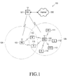
- FIGURE 1 illustrates a wireless network according to embodiments of the present disclosure
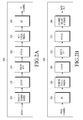
- FIGURE 2A illustrates a high-level diagram of a wireless transmit path according to embodiments of the present disclosure
- FIGURE 2B illustrates a high-level diagram of a wireless receive path according to embodiments of the present disclosure
- FIGURE 3 illustrates a subscriber station according to embodiments of the present disclosure
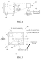
- FIGURE 4 illustrates a transmission point equipped with 2D active antenna array according to embodiments of the present disclosure
- FIGURE 5 illustrates azimuth and elevation angles to a mobile station from the 2D active antenna array according to embodiments of the present disclosure
- FIGURE 6 illustrates H-PMI and V-PMI according to embodiments of the present disclosure
- FIGURE 7 illustrates a first and a second CSI-RS APs according to embodiments of the present disclosure
- FIGURES 8A through 8C illustrates joint configuration of A- and B- CSI-RS according to embodiments of the present disclosure
- FIGURE 9 illustrates Vertical CSI-RS APs and horizontal CSI-RS APs according to embodiments of the present disclosure
- FIGURES 10 and 11 illustrate construction of the horizontal and the vertical CSI-RS APs according to embodiments of the present disclosure
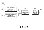
- FIGURE 12 illustrates first and second sets of horizontal CSI-RS APs according to embodiments of the present disclosure
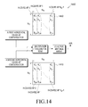
- FIGURES 13 and 14 illustrate construction of two sets of H-CSI-RS APs according to embodiments of the present disclosure
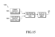
- FIGURE 15 illustrates primary and secondary CSI-RS APs according to embodiments of the present disclosure.
- FIGURE 16 illustrates construction of the primary and the secondary CSI-RS according to embodiments of the present disclosure.
- FIGURES 1 through 16 discussed below, and the various embodiments used to describe the principles of the present disclosure in this patent document are by way of illustration only and should not be construed in any way to limit the scope of the disclosure. Those skilled in the art will understand that the principles of the present disclosure may be implemented in any suitably arranged wireless communication system.
- FIGURE 1 illustrates a wireless network 100 according to one embodiment of the present disclosure.
- the embodiment of wireless network 100 illustrated in FIGURE 1 is for illustration only. Other embodiments of wireless network 100 could be used without departing from the scope of this disclosure.
- the wireless network 100 includes a base sta eNodeB (eNB) 101, eNB 102, and eNB 103.
- the eNB 101 communicates with eNB 102 and eNB 103.
- the eNB 101 also communicates with Internet protocol (IP) network 130, such as the Internet, a proprietary IP network, or other data network.
- IP Internet protocol
- eNodeB eNodeB
- base station eNodeB
- access point eNodeB
- eNodeB eNodeB
- UE user equipment
- SS subscriber stations
- RT remote terminal
- WT wireless terminal
- the eNB 102 provides wireless broadband access to network 130 to a first plurality of user equipments (UEs) within coverage area 120 of eNB 102.
- the first plurality of UEs includes UE 111, which may be located in a small business; UE 112, which may be located in an enterprise; UE 113, which may be located in a WiFi hotspot; UE 114, which may be located in a first residence; UE 115, which may be located in a second residence; and UE 116, which may be a mobile device, such as a cell phone, a wireless laptop, a wireless PDA, or the like.
- UEs 111-116 may be any wireless communication device, such as, but not limited to, a mobile phone, mobile PDA and any mobile station (MS).
- the eNB 103 provides wireless broadband access to a second plurality of UEs within coverage area 125 of eNB 103.
- the second plurality of UEs includes UE 115 and UE 116.
- one or more of eNBs 101-103 may communicate with each other and with UEs 111-116 using 5G, LTE, LTE-A, or WiMAX techniques including techniques for using a new channel-state-information pilot design as described in embodiments of the present disclosure.
- Dotted lines show the approximate extents of coverage areas 120 and 125, which are shown as approximately circular for the purposes of illustration and explanation only. It should be clearly understood that the coverage areas associated with base stations, for example, coverage areas 120 and 125, may have other shapes, including irregular shapes, depending upon the configuration of the base stations and variations in the radio environment associated with natural and man-made obstructions.
- FIGURE 1 depicts one example of a wireless network 100
- another type of data network such as a wired network
- network terminals may replace eNBs 101-103 and UEs 111-116.
- Wired connections may replace the wireless connections depicted in FIGURE 1 .
- FIGURE 2A is a high-level diagram of a wireless transmit path.
- FIGURE 2B is a high-level diagram of a wireless receive path.
- the transmit path 200 may be implemented, e.g., in eNB 102 and the receive path 250 may be implemented, e.g., in a UE, such as UE 116 of FIGURE 1 .
- the receive path 250 could be implemented in an eNB (e.g. eNB 102 of FIGURE 1 ) and the transmit path 200 could be implemented in a UE.
- transmit path 200 and receive path 250 are configured to perform methods for communication using a new channel-state-information pilot design as described in embodiments of the present disclosure.
- Transmit path 200 comprises channel coding and modulation block 205, serial-to-parallel (S-to-P) block 210, Size N Inverse Fast Fourier Transform (IFFT) block 215, parallel-to-serial (P-to-S) block 220, add cyclic prefix block 225, up-converter (UC) 230.
- Receive path 250 comprises down-converter (DC) 255, remove cyclic prefix block 260, serial-to-parallel (S-to-P) block 265, Size N Fast Fourier Transform (FFT) block 270, parallel-to-serial (P-to-S) block 275, channel decoding and demodulation block 280.
- DC down-converter
- FFT Fast Fourier Transform
- FIGURES 2A and 2B may be implemented in software while other components may be implemented by configurable hardware (e.g., a processor) or a mixture of software and configurable hardware.
- configurable hardware e.g., a processor
- the FFT blocks and the IFFT blocks described in this disclosure document may be implemented as configurable software algorithms, where the value of Size N may be modified according to the implementation.
- the value of the N variable may be any integer number (i.e., 1, 2, 3, 4, etc.), while for FFT and IFFT functions, the value of the N variable may be any integer number that is a power of two (i.e., 1, 2, 4, 8, 16, etc.).
- channel coding and modulation block 205 receives a set of information bits, applies coding (e.g., LDPC coding) and modulates (e.g., Quadrature Phase Shift Keying (QPSK) or Quadrature Amplitude Modulation (QAM)) the input bits to produce a sequence of frequency-domain modulation symbols.
- Serial-to-parallel block 210 converts (i.e., de-multiplexes) the serial modulated symbols to parallel data to produce N parallel symbol streams where N is the IFFT/FFT size used in eNB 102 and UE 116.
- Size N IFFT block 215 then performs an IFFT operation on the N parallel symbol streams to produce time-domain output signals.
- Parallel-to-serial block 220 converts (i.e., multiplexes) the parallel time-domain output symbols from Size N IFFT block 215 to produce a serial time-domain signal.
- Add cyclic prefix block 225 then inserts a cyclic prefix to the time-domain signal.
- up-converter 230 modulates (i.e., up-converts) the output of add cyclic prefix block 225 to RF frequency for transmission via a wireless channel.
- the signal may also be filtered at baseband before conversion to RF frequency.
- the transmitted RF signal arrives at UE 116 after passing through the wireless channel and reverse operations to those at eNB 102 are performed.
- Down-converter 255 down-converts the received signal to baseband frequency and remove cyclic prefix block 260 removes the cyclic prefix to produce the serial time-domain baseband signal.
- Serial-to-parallel block 265 converts the time-domain baseband signal to parallel time domain signals.
- Size N FFT block 270 then performs an FFT algorithm to produce N parallel frequency-domain signals.
- Parallel-to-serial block 275 converts the parallel frequency-domain signals to a sequence of modulated data symbols.
- Channel decoding and demodulation block 280 demodulates and then decodes the modulated symbols to recover the original input data stream.
- Each of eNBs 101-103 may implement a transmit path that is analogous to transmitting in the downlink to UEs 111-116 and may implement a receive path that is analogous to receiving in the uplink from UEs 111-116.
- each one of UEs 111-116 may implement a transmit path corresponding to the architecture for transmitting in the uplink to eNBs 101-103 and may implement a receive path corresponding to the architecture for receiving in the downlink from eNBs 101-103.
- FIGURE 3 illustrates a subscriber station according to embodiments of the present disclosure.
- the embodiment of subscribe station, such as UE 116, illustrated in FIGURE 3 is for illustration only. Other embodiments of the wireless subscriber station could be used without departing from the scope of this disclosure.
- UE 116 comprises antenna 305, radio frequency (RF) transceiver 310, transmit (TX) processing circuitry 315, microphone 320, and receive (RX) processing circuitry 325. Although shown as a single antenna, antenna 305 can include multiple antennas.
- SS 116 also comprises speaker 330, main processor 340, input/output (I/O) interface (IF) 345, keypad 350, display 355, and memory 360.
- Memory 360 further comprises basic operating system (OS) program 361 and a plurality of applications 362.
- the plurality of applications can include one or more of resource mapping tables (Tables 1-10 described in further detail herein below).
- Radio frequency (RF) transceiver 310 receives from antenna 305 an incoming RF signal transmitted by a base station of wireless network 100. Radio frequency (RF) transceiver 310 down-converts the incoming RF signal to produce an intermediate frequency (IF) or a baseband signal. The IF or baseband signal is sent to receiver (RX) processing circuitry 325 that produces a processed baseband signal by filtering, decoding, and/or digitizing the baseband or IF signal. Receiver (RX) processing circuitry 325 transmits the processed baseband signal to speaker 330 (i.e., voice data) or to main processor 340 for further processing (e.g., web browsing).
- IF intermediate frequency
- RX receiver
- Receiver (RX) processing circuitry 325 transmits the processed baseband signal to speaker 330 (i.e., voice data) or to main processor 340 for further processing (e.g., web browsing).
- Transmitter (TX) processing circuitry 315 receives analog or digital voice data from microphone 320 or other outgoing baseband data (e.g., web data, e-mail, interactive video game data) from main processor 340. Transmitter (TX) processing circuitry 315 encodes, multiplexes, and/or digitizes the outgoing baseband data to produce a processed baseband or IF signal. Radio frequency (RF) transceiver 310 receives the outgoing processed baseband or IF signal from transmitter (TX) processing circuitry 315. Radio frequency (RF) transceiver 310 up-converts the baseband or IF signal to a radio frequency (RF) signal that is transmitted via antenna 305.
- RF radio frequency
- main processor 340 is a microprocessor or microcontroller.
- Memory 360 is coupled to main processor 340.
- part of memory 360 comprises a random access memory (RAM) and another part of memory 360 comprises a Flash memory, which acts as a read-only memory (ROM).
- RAM random access memory
- ROM read-only memory
- Main processor 340 executes basic operating system (OS) program 361 stored in memory 360 in order to control the overall operation of wireless subscriber station 116. In one such operation, main processor 340 controls the reception of forward channel signals and the transmission of reverse channel signals by radio frequency (RF) transceiver 310, receiver (RX) processing circuitry 325, and transmitter (TX) processing circuitry 315, in accordance with well-known principles.
- OS basic operating system
- Main processor 340 is capable of executing other processes and programs resident in memory 360, such as operations for performing communications including a new channel-state-information pilot design as described in embodiments of the present disclosure. Main processor 340 can move data into or out of memory 360, as required by an executing process. In some embodiments, the main processor 340 is configured to execute a plurality of applications 362, such as applications for CoMP communications and MU-MIMO communications. The main processor 340 can operate the plurality of applications 362 based on OS program 361 or in response to a signal received from BS 102. Main processor 340 is also coupled to I/O interface 345. I/O interface 345 provides subscriber station 116 with the ability to connect to other devices such as laptop computers and handheld computers. I/O interface 345 is the communication path between these accessories and main controller 340.
- I/O interface 345 provides subscriber station 116 with the ability to connect to other devices such as laptop computers and handheld computers. I/O interface 345 is the communication path between these accessories and main controller 340.
- Main processor 340 is also coupled to keypad 350 and display unit 355.
- the operator of subscriber station 116 uses keypad 350 to enter data into subscriber station 116.
- Display 355 may be a liquid crystal display capable of rendering text and/or at least limited graphics from web sites. Alternate embodiments may use other types of displays.
- Embodiments of the present disclosure provide methods and apparatus to for a channel-state-information (CSI) pilot design for advanced wireless communications system.
- CSI-RS channel-state-information reference signal
- a information element (IE) CSI-RS configuration (CSI-RS-Config) is used to specify the CSI-RS configuration as shown in here:
- antennaPortsCount Parameter represents the number of antenna ports used for transmission of CSI reference signals where an1 corresponds to 1, an2 to 2 antenna ports etc. see TS 36.211 [21, 6.10.5].
- p-C Parameter P c , see TS 36.213 [23, 7.2.5].
- resourceConfig Parameter CSI reference signal configuration, see TS 36.211 [21, table 6.10.5.2-1 and 6.10.5.2-2].
- subframeConfig Parameter I CSI-RS , see TS 36.211 [21, table 6.10.5.3-1].
- zeroTxPowerResourceConfigList Parameter ZeroPowerCSI-RS, see TS 36.211 [21, 6.10.5.2].
- zeroTxPowerSubframeCoufig Parameter I CSI-RS , see TS 36.211 [21, table 6.10.5.3-1].
- the cell-specific subframe configuration period T CSI-RS and the cell-specific subframe offset ⁇ CSI-RS for the occurence of CSI reference signals are listed in TABLE 2.
- the parameter I CSI-RS can be configured separately for CSI reference signals for which UE 116 assume non-zero and zero transmission power.
- CSI reference signal subframe configuration CSI-RS-SubframeConfig I CSI-RS CSI-RS periodicity
- T CSI-RS (subframes) CSI-RS subframe offset ⁇ CSI-RS (subframes) 0-4 5 I CSI-RS 5-14 10 I CSI-RS -5 15-34 20 I CSI-RS -15 35-74 40 I CSI-RS -35 75-154 80 I CSI-RS -75
- CSI-RS sequence generation is explained as in the following section 6.10.5.1 - Sequence generation:
- the pseudo-random sequence c(i) is defined in Section 7.2.
- Configuration of multiple non-zero-power CSI-RS resources includes at least:
- Two antenna ports are said to be quasi co-located if the large-scale properties of the channel over which a symbol on one antenna port is conveyed can be inferred from the channel over which a symbol on the other antenna port is conveyed.
- the large-scale properties include one or more of delay spread, Doppler spread, Doppler shift, average gain, and average delay.
- UE 116 in transmission mode 10 can be configured with one or more CSI processes per serving cell by higher layers. Each CSI process is associated with a CSI-RS resource (defined in Section 7.2.5) and a CSI-interference measurement (CSI-IM) resource (defined in Section 7.2.6). A CSI reported by UE 116 corresponds to a CSI process configured by higher layers. Each CSI process can be configured with or without PMI/RI reporting by higher layer signalling.
- CSI-RS resource defined in Section 7.2.5
- CSI-IM CSI-interference measurement
- UE116 derives the interference measurements for computing the CQI value reported in uplink subframe n and corresponding to a CSI process, based on only the zero power CSI-RS (defined in REF3) within the configured CSI-IM resource associated with the CSI process. If UE 116 in transmission mode 10 is configured by higher layers for CSI subframe sets C CSI,0 and C CSI,1 , the configured CSI-IM resource within the subframe subset belonging to the CSI reference resource is used to derive the interference measurement.
- CSI-Process is the CSI process configuration that E-UTRAN can configure on a serving frequency.
- CSI-Process field descriptions antennaInfoDedConfigId refers to a dedicated antenna info configuration that is configured for the same frequency as the CSI process.
- csi-IM-Identity refers to a CSI-IM configuration that is configured for the same frequency as the CSI process.
- csi-RS-IdentityNZP refers to a CSI RS configuration that is configured for the same frequency as the CSI process.
- cqi-ReportBothPS Includes CQI configuration parameters applicable for both aperiodic and periodic CSI reporting, for which CSI process specific values may be configured.
- E-URAN configures the field if and only if cqi-ReportPeriodicId is included and/ or if cqi-ReportAperiodicPS is included and set to setup.
- cqi-ReportPeriodicId refers to a periodic CQI reporting configuration that is configured for the same frequency as the CSI process. Value 0 refers to the set of parameters defined by the REL-10 CQI reporting configuration fields, while the other values refer to the additional configurations
- E-UTRAN assigns by CQI-ReportPeriodicExt-r11 (and as covered by CQI-ReportPeriodicExtId ).
- p-C Parameter: P c see TS 36.213 [23, 7.2.5].
- p-C-AndAntennaInfoDedList including 2 entries indicates that the subframe patterns configured for CSI (CQI/PMI/PTI/RI) reporting (i.e. as defined by field csi-MeasSubframeSet1 and csi-MeasSubframeSet2) are to be used for this CSI process, while a single entry indicates that the subframe patterns are not to be used for this CSI process.
- E-UTRAN does not include 2 entries in p-C-AndAntennaInfoDedList for CSI processes concerning a secondary frequency.
- E-UTRAN includes 2 entries in p-C-AndAntennaInfoDedList when configuring both cqi-pmi-ConfigIndex and cqi-pmi-ConfigIndex2.
- the IE CSI-Processldentity is used to identify a CSI process that is configured by the IE CSI-Process. The identity is unique within the scope of a carrier frequency.
- the IE CSI-RS-ConfigNZP is the CSI-RS resource configuration using non-zero power transmission that E-UTRAN may configure on a serving frequency.
- CSI-RS-ConfigZP the IE CSI-RS-ConfigZP is the CSI-RS resource configuration, for which UE 116 assumes zero transmission power, that E-UTRAN can configure on a serving frequency.
- CSI-RS-ConfigZP field descriptions resourceConfigList Parameter: CSI reference signal configuration, see TS 36.211 [21, table 6.10.5.2-1 and 6.10.5.2-2].
- the IE CSI-RS-IdentityNZP is used to identify a CSI-RS resource configuration using non-zero transmission power, as configured by the IE CSI-RS-ConfigNZP.
- the identity is unique within the scope of a carrier frequency.
- the IE CSI-RS-IdehtityZP is used to identify a CSI-RS resource configuration for which UE assumes zero transmission power, as configured by the IE CSI-RS-ConfigZP.
- the identity is unique within the scope of a carrier frequency.
- CSI-IM-CONFIG the IE CSI-IM-Config is the CSI-IM configuration that E-UTRAN may configure on a serving frequency.
- CSI-IM-Config field descriptions resourceConfig Parameter: CSI-IM configuration, see TS 36.211 [21, table 6.10.5.2-1 and 6.10.5.2-2] for 4 REs.
- the IE CSI-IM-Identity is used to identify a CSI-IM configuration that is configured by the IE CSI-IM-Config.
- the identity is unique within the scope of a carrier frequency.
- transmission points are a network node can transmit downlink signals and receive uplink signals in a cellular network, examples of which include base stations, NodeBs, enhanced NodeBs (eNBs) remote radio heads (RRHs), and so forth.
- TPs transmission points
- eNBs enhanced NodeBs
- RRHs remote radio heads
- an entity controlling at least one TP is called the controller, the network or eNB.
- Each active antenna array may have separate base band, which could dynamically control the antenna weights in frequency selective manner.
- FIGURE 4 illustrates a transmission point equipped with 2D active antenna array according to embodiments of the present disclosure.
- the embodiment of the transmission point 400 shown in FIGURE 4 is for illustration only. Other embodiments could be used without departing from the scope of this disclosure.
- the transmission point 400 includes an antenna array 405 and a controller 410.
- the horizontal spacing between any two closest antenna elements is denoted by d H 420, and the vertical spacing between any two closest antenna elements is denoted by dv 425.
- FIGURE 5 illustrates azimuth and elevation angles to a mobile station from the 2D active antenna array according to embodiments of the present disclosure.
- the embodiment of the 2D active antenna array 405 shown in FIGURE 5 is for illustration only. Other embodiments could be used without departing from the scope of this disclosure.
- a transmission vector between the transmission point 400 equipped with 2D antenna array and UE 116 is transmitted at azimuth and elevation angles.
- antenna elements 415 are placed in a rectangle on XZ plane in an orthogonal XYZ coordinate system.
- the origin 505 of the coordinate system is placed at the center of the rectangle.
- the azimuth (horizontal) angle ⁇ k 510 for UE 116 is defined as the angle between Y axis 515 and the projection vector 520 of a straight line between the TP and UE 116 to the XY plane.
- the elevation (vertical) angle ⁇ k 525 is defined as the angle between Y axis and the projection vector of the straight line to the YZ plane.
- the network utilizes UEs' channel state information (CSI) to schedule time-frequency resources, to select precoders and modulation and coding schemes (MCS) for each individual UE.
- CSI channel state information
- MCS modulation and coding schemes
- the network can configure and transmit CSI reference signals (CSI-RS).
- CSI-RS CSI reference signals
- each UE can be configured to feed back estimated precoding matrix information (PMI), channel quality information (CQI) and rank information (RI), by receiving and processing the CSI-RS.
- PMI estimated precoding matrix information
- CQI channel quality information
- RI rank information
- the UEs' CSI feedback is designed with mainly targeting horizontal CSI associated with the azimuth angles.
- PMI/CQI feedback for downlink beamforming in LTE informs the eNB the horizontal direction (or the azimuth angle) along which the UE receives the strongest signal and the associated channel strength.
- active antenna array elements are introduced in the vertical domain as well, the necessity of vertical CSI feedback emerges.
- the corresponding CSI-RS design is crucial.
- Embodiments of the present disclosure illustrate CSI-RS designs and associated configuration methods to be used in the wireless communication networks (e.g., cellular networks) having TPs equipped with 2D active antenna array. It is noted that unless otherwise specified, the CSI-RS disclosed herein refers to NZP CSI-RS.
- TM transmission mode
- UE 116 When UE 116 is configured with TM X, UE 116 receives PDSCHs from the 2D active antenna array 405, and is configured with a newly designed CSI-RS.
- the MIMO transmission from the 2D active antenna array 405 is also referenced as full-dimensional MIMO or FD-MIMO.
- TP 400 is capable of transmitting all the N CSI-RS ant enna ports (APs) associated with each of the N antenna elements 415, and the network is capable of configuring all the N CSI-RS APs to each UE using a UE-specific RRC configuration or a br oadcast signaling, so that UE 116 can estimate the full CSI associated with the N antenna elemen ts 415.
- APs ant enna ports
- TP 400 is capable of transmitting at least two sets of CSI-RS APs, and the network is capable of configuring the at least two sets of CSI-RS APs to each UE, wherein UE 116 derives and feeds back horizontal CSI (H-CSI) and vertical CSI (V-C SI) estimated by receiving and processing the at least two sets of CSI-RS.
- H-CSI horizontal CSI
- V-C SI vertical CSI
- the total number of CSI-RS APs can be less than N, and hence the CSI-RS transmission overhead is reduced as co mpared to method 1.
- the H-CSI of a UE is horizontal CSI estimat ed at UE 116, which are channel characteristics mainly associated with horizontally placed anten na elements 415 at TP 400.
- the horizontal CSI includes horizontal CQI (H-CQI), horizontal PM I (H-PMI) and horizontal RI (H-RI).
- H-CSI can be the same as the CSI (PMI, CQI and RI) in another LTE system, because the certain LTE systems CSI feedback contents and mechanism are designed considering horizontal antenna array.
- the V-CSI of a UE is vertical CSI estimated at UE 116, which are channel charac teristics mainly associated with vertically placed antenna elements at TP 400.
- the vertical CSI in cludes vertical CQI (V-CQI), vertical PMI (V-PMI) and vertical RI (V-RI).
- FIGURE 6 illustrates H-PMI and V-PMI according to embodiments of the present disclosure.
- the embodiment of the H-PMI and V-PMI 600 shown in FIGURE 6 is for illustration only. Other embodiments could be used without departing from the scope of this disclosure.
- UE 1 116, UE 2 115 and UE 3 114 receives the strongest signal when the (H-PMI, V-PMI) pairs are (P1,Q1), (P2,Q2) and (P3,Q3), respectively, according to their respective horizontal directions (or azimuth angles) and vertical directions (or elevation angles).
- H-PMIs When configured to feed back H-PMIs, UE 1 116, UE 2 115 and UE 3 114 report H-PMIs P1 605, P2 610 and P3 615, respectively.
- UE 1 116, UE 2 115 and UE 3 114 report V-PMIs Q1 620, Q2 625 and Q3 630, respectively.
- CQI two feedback methods can be considered: 1) H-CQI and V-CQI are separately derived and are independently fed back to the network; and 2) One joint CQI is derived and is fed back to the network for the N antenna channel.
- UE 116 constructs a desired precoding matrix for the N-Tx antenna channel using H-PMI and V-PMI, and calculates a received power under the assumption that the TP transmits signals using the precoding matrix. From the received power, UE 116 derives CQI, where the CQI can be a desired MCS.
- Joint RI is the rank information about the MIMO channels between the N -Tx antenna and a number of receive antennas at the UE.
- FIGURE 6 illustrates only line-of-sight channels.
- the non-line-of-sight channels, the V-CSI and H-CSI can be described and defined in a similar way.
- the example shown in FIGURE 6 is for illustration only and it does not prevent other similar constructions and definitions of V-CSI and H-CSI.
- FIGURE 7 illustrates a first and a second CSI-RS APs according to embodiments of the present disclosure.
- the embodiment of the transmitter chain 700 including the first and second CSI-RS APs shown in FIGURE 7 is for illustration only. Other embodiments could be used without departing from the scope of the present disclosure.
- the transmitter chain 700 is configured for multiplexing a first set of CSI-RS 705 (denoted by A-CSI-RS APs) and a second set of CSI-RS APs 710 (denoted by B-CSI-RS APs) for the at least two sets of CSI-RS APs.
- the multiplexer operation 715 for A-CSI-RS APs 705 and B-CSI-RS APs 710 can be time-domain multiplexing (TDM), CDM (code-domain multiplexing), FDM (frequency-domain multiplexing) and SDM (spatial-domain multiplexing) and any combination of TDM, FDM, CDM and SDM.
- A-CSI-RS APs 705 and B-CSI-RS APs 710 transmit their CSI-RS at two different time location, e.g., in two different time slots, or in two different subframes, or in two different sets of OFDM symbols.
- A-CSI-RS APs 705 and B-CSI-RS APs 710 transmit their CSI-RS at two different frequency (or subcarrier) location.
- A-CSI-RS APs 705 and B-CSI-RS APs 710 transmit their CSI-RS using two different orthogonal codes (e.g., Walsh code, CAZAC code) in the same time-frequency location.
- orthogonal codes e.g., Walsh code, CAZAC code
- A-CSI-RS APs 705 and B-CSI-RS APs 710 transmit their CSI-RS in two different spatial beams, and they can be differently scrambled using two different scrambling initializations.
- TDM, CDM, FDM and SDM Some example combinations of TDM, CDM, FDM and SDM are described below.
- FDM/TDM multiplexing is applied, A-CSI-RS APs 705 and B-CSI-RS APs 710 transmit their CSI-RS at two different time-frequency location. Two sets of CSI-RS APs are (quasi) co-located if large-scale propagation properties of the channel over which a symbol on the first antenna port is conveyed can be inferred from the channel over which another symbol on the other antenna port is conveyed.
- (A-CSI-RS, B-CSI-RS) can be (H-CSI-RS, V-CSI-RS), (a first H-CSI-RS, a second H-CSI-RS), (a primary CSI-RS, a secondary CSI-RS), as illustrated in later embodiments.
- the CSI-RS configurations defined in Rel-10 LTE or Rel-11 LTE is reused for configuring each of A-CSI-RS and B-CSI-RS.
- Rel-10 LTE CSI-RS configuration some of the following parameters in the Table 3 are separately configured for each of A-CSI-RS and B-CSI-RS.
- AntennaPortsCount Parameter represents the number of antenna ports used for transmission of CSI reference signals where an1 corresponds to 1, an2 to 2 antenna ports etc. see TS 36.211 [21, 6.10.5].
- resourceConfig Parameter CSI reference signal configuration, see TS 36.211 [21, table 6.10.5.2-1 and 6.10.5.2-2].
- subframeConfig Parameter I CSI-RS , see TS 36.211 [21, table 6.10.5.3-1].
- CSI-RS-ConfigNZP-r11 When Rel-11 LTE NZP CSI-RS configuration is used, some of the parameters defining a CSI-RS-ConfigNZP-r11 (whose fields are copied below and in the background section) are separately configured for each of A-CSI-RS and B-CSI-RS.
- the resource configurations ( resourceConfig ) and AntennaPortsCount for A-CSI-RS and B-CSI-RS can be independently or jointly configured.
- ( A-resourceConfig, A-AntennaPortsCount ) and ( B-resourceConfig, B-AntennaPortCount ) are configured for A-CSI-RS and B-CSI-RS.
- UE 116 derives each of A-CSI-RS pattern B-CSI-RS pattern with replacing (resourceConfig,AntennaPortCount) by each of (A-resourceConfig,A-AntennaPortCount) and (B-resourceConfig, B-AntennaPortCount) according to TABLE 1.
- (resourceConfig,AntennaPortCount) is configured for both A-CSI-RS and B-CSI-RS.
- (resourceConfig,AntennaPortCount) is configured to UE 116
- UE 116 first derives a CSI-RS pattern according to TABLE 1 with the configured (resourceConfig,AntennaPortCount).
- N 1 and N 2 can be RRC configured or be constants in the standard specification.
- A-CSI-RS and B-CSI-RS are FDM-multiplexed; and multiple CSI-RS ports in each of A-CSI-RS and B-CSI-RS are CDM multiplexed.
- the 8 CSI-RS are multiplexed in 4 CDM groups of 2 REs each, wherein a first CDM code, e.g., [+1, +1] is assigned for A-CSI-RS; and a second CDM code, e.g., [+1, -1] is assigned for B-CSI-RS.
- the resource configurations ( resourceConfig ) and AntennaPortsCount for A-CSI-RS and B-CSI-RS can be independently or jointly configured.
- ( A-resourceConfig, A-AntennaPortsCount ) and ( B-resourceConfig, B-AntennaPortCount ) are configured for A-CSI-RS and B-CSI-RS.
- UE 116 derives each of A-CSI-RS pattern B-CSI-RS pattern with replacing (resourceConfig,AntennaPortCount) by each of (A-resourceConfig,A-AntennaPortCount) and (B-resourceConfig, B-AntennaPortCount) according to TABLE 1.
- (resourceConfig,AntennaPortCount) is configured for both A-CSI-RS and B-CSI-RS.
- (resourceConfig,AntennaPortCount) is configured to UE 116
- UE 116 first derives a CSI-RS pattern according to TABLE 1 with the configured (resourceConfig,AntennaPortCount).
- N 1 and N 2 can be RRC configured or be constants in the standard specification.
- A-CSI-RS and B-CSI-RS are FDM-multiplexed; and multiple CSI-RS ports in each of A-CSI-RS and B-CSI-RS are CDM multiplexed.
- the 8 CSI-RS are multiplexed in 4 CDM groups of 2 REs each, wherein a first CDM code, e.g., [+1, +1] is assigned for A-CSI-RS; and a second CDM code, e.g., [+1, -1] is assigned for B-CSI-RS.
- FIGURES 8A through 8C illustrates joint configuration of A- and B- CSI-RS acc ording to embodiments of the present disclosure.
- the embodiments of the joint configuration 80 0, 810, 820 shown in FIGURES 8A through 8C are for illustration only. Other embodiments cou ld be used without departing from the scope of this disclosure.
- a common AntennaPortCount is configured for both A-C SI-RS and B-CSI-RS, and at the same time, A- resourceConfig and B-resourceConfig are separat ely configured for UE 116.
- UE 116 derives A-CSI-RS pattern and B-CSI-RS pattern with (A-resourceConfig,AntennaPortCount) and (B-resourceConfig,AntennaPortCount), respect ively.
- the total N number of antenna ports at TP 400 can be additionally sign aled from A-AntennaPortCount and B- AntennaPortCount.
- subframeConfig The subframe configurations ( subframeConfig ) for A-CSI-RS and B-CSI-RS can be independently or jointly configured.
- the subframe period and the subframe offset for the occurrence are configured as in the same way as the Rel-10 CSI-RS are configured.
- two parameters are configured to UE 116, i.e., A-CSI-RS-SubframeConfig and B-CSI-RS -SubframeConfig and UE 116 derives the subfra me period and the subframe offset for the occurrence of each of B-CSI-RS and A-CSI-RS accord ing to TABLE 2, with replacing CSI-RS -SubframeConfig by each of A-CSI-RS- SubframeConfig and B-CSI-RS- SubframeConfig.
- the subf rame configuration period and the subframe offset for the occurrence are configured as in the sa me way as the Re1-10 CSI-RS are configured.
- one parameter is configured to UE 11 6 as in Rel-10, i.e., CSI-RS -SubframeConfig and UE 116 derives the subframe period and the su bframe offset for the occurrence of both B-CSI-RS and A-CSI-RS according to TABLE 2 with th e configured CSI-RS- SubframeConfig.
- (A-CSI-RS, B-CSI-RS) can be (H-CSI-RS, V-CSI-RS), (a first H-CSI-RS, a second H-CSI-RS), (a primary CSI-RS, a secondary CSI-RS), as illustrated in later em bodiments.
- CSI-Process-r12 For configuration of CSI-RS transmission and CSI feedback for UE 116 configure d with TM X, a new CSI process, referenced hereafter as CSI-Process-r12, is defined. To facilitat e joint CQI transmission, the new CSI process is associated with two CSI resources, i.e., A-CSI-RS and B-CSI-RS, rather than one CSI-RS and one CSI-IM.
- CSI-process-r12 One illustration example construction of CSI-process-r12 is described below, whe re a common Pc (p-C-AndAntennaInfoDedList-r12) is configured for A-CSI-RS and B-CSI-RS.
- CSI-Pr p-C-AndAntennaInfoDedList-r12
- a CSI-RS type when configuring a set of CSI-RS, is sign aled in addition to other CSI-RS configuration parameters, e.g., CSI-RS pattern, subframe period , subframe offset, and power.
- the signaling can be either UE-specific or cell-specific.
- UE 116 derives CSI differently with estimating ch annels using the configured CSI-RS, e.g., based on different PMI codebooks.
- a first CSI-RS type is associated with a first PMI codebook
- a second CSI-RS type is associated with a second PMI codebook
- the first and the second PMI codebooks can be a horizontal PMI codebook and a vertical PMI codebook, respectively.
- the horizontal PMI codebook can be the same as one of Rel-8 and Rel-10 downlink 2-Tx, 4-Tx and 8-Tx PMI codebooks defined in the LTE specificat ions; and the vertical PMI codebook can be differently designed from the Rel-8 and Rel-10 down link 2-Tx, 4-Tx and 8-Tx codebooks.
- the first and the second PMI codebooks can have different sizes. That is, the first and the second PMI codebooks are composed of M 1 number of PMI matrices and M 2 number of PMI matrices respectively, wherein M 1 and M 2 can be different.
- UE 116 is configured with a first set of CSI-RS of a first CSI-RS type and a second set of CSI-RS of a second CSI-RS type.
- UE 116 derives a first PMI ac cording to the first PMI codebook with estimating channels using the first set of CSI-RS.
- UE 11 6 also derives a second PMI according to the second PMI codebook with estimating channels usi ng the second set of CSI-RS.
- the feedback reporting of the first PMI and the second PMI is configured either j ointly or independently.
- the fir st PMI and the second PMI are reported to the eNB 102 according to the respective configuration s.
- both the first PMI and the seco nd PMI are reported in a single uplink physical channel transmitted in a subframe, e.g., on a PUS CH or a PUCCH.
- a PMI codebook information is sign aled in addition to the other CSI-RS configuration parameters.
- UE 116 derives PMI with estimating channels using the configured CSI-RS.
- UE 116 when UE 116 is configured with a first set of CSI-RS and the first PMI codebook; and a seco nd set of CSI-RS and the second PMI codebook, then, UE 116 derives a first PMI according to th e first PMI codebook with estimating channels using the first set of CSI-RS.
- UE 116 derives a second PMI according to the second PMI codebook with estimating channels using the second set of CSI-RS.
- the first PMI codebook and the second PMI codebook ar e a horizontal PMI codebook and a vertical PMI codebook, respectively.
- a CSI-RS configuration is implicitly associated with a PMI codebook.
- PMI estimated with A-CSI-RS (a-csi-RS-IdentityNZP-r12) is selected from the first codebook; and PMI estimat ed with B-CSI-RS (a-csi-RS-IdentityNZP-r12) is selected from the second codebook.
- FIGURE 9 illustrates Vertical CSI-RS APs and horizontal CSI-RS APs according to embodiments of the present disclosure.
- the embodiment of the transmitter chain 900 includedin g the Vertical CSI-RS APs and horizontal CSI-RS APs shown in FIGURE 9 is for illustration onl y. Other embodiments could be used without departing from the scope of the present disclosure.
- two sets of CSI-RS APs 905, 910 out of the at least two s ets of CSI-RS APs are separately constructed: one set consists of N V vertical CSI-RS (V-CSI-RS ) APs 905 , and the other set consists of N H horizontal CSI-RS (H-CSI-RS) APs 910.
- the h perspectiveal CSI-RS APs 910 are used for UEs' horizontal CSI (H-CSI) estimation
- the vertical CSI-RS APs 905 is used for UEs' vertical CSI (V-CSI) estimation.
- H-CSI-RS is associated with H-PMI codebook and V-CS I-RS is associated with V-PMI codebook.
- H-PMI codebook and V-CSI-RS codebook can be identical.
- 3GPP LTE Rel-8 and Rel-10 2-Tx, 4-Tx and 8-Tx DL codeboo ks are reused for both H-PMI and V-PMI.
- UE 116 derives H-CSI using H-CSI-RS by applying the same procedure used for deriving Rel-10 CQI/PMI/RI based on Rel-1 0 CSI-RS.
- UE 116 derives V-CSI using V-CSI-RS by applying the sam e procedure used for deriving Rel-10 CQI/PMI/RI based on Rel-10 CSI-RS.
- 3GPP LTE Rel-8 and Rel-10 2-Tx, 4-Tx, and 8-Tx DL cod ebooks are reused for H-PMI codebook only and V-PMI codebook is newly designed; or both th e H-PMI and the V-PMI codebooks are newly designed.
- the CSI-RS configuration can include a CSI-RS type field, to indicate whet her the configured CSI-RS is H-CSI-RS or V-CSI-RS.
- UE 116 When UE 116 is configured with H-CSI-RS, UE 116 derives a PMI (H-PMI) using the H-PMI codebook with estimating channels using H-CSI-RS.
- UE 116 when UE 116 is configured with V-CSI-RS, UE 116 derives a PMI (V -PMI) using the V-PMI codebook with estimating channels using V-CSI-RS.
- the CSI-RS configuration can include a PMI codebook information fiel d, to indicate which PMI codebook should be used for deriving PMI using the configured CSI-R S.
- UE 11 6 derives a PMI (H-PMI) using the H-PMI codebook with estimating channels using the configur ed CSI-RS; on the other hand when UE 116 receives a configuration signaling of a CSI-RS and a V-PMI codebook, UE 116 derives a PMI (V-PMI) using the V-PMI codebook with estimating c hannels using the configured CSI-RS.
- V-PMI PMI codebook information fiel d
- a PMI codebook information can be separately signaled fro m the CSI-RS configuration. Then, UE 116 derives H-PMI and V-PMI using either a first PMI c odebook or a second PMI codebook, depending on the configured PMI codebook information.
- the first PMI codebook can be 3GPP LTE Rel-8 and Rel-10 2-Tx, 4-Tx, and 8-Tx DL codebooks; and the second PMI codebook can be a newly designed codebook.
- the codebook sizes of the H-PMI codebook and the V-P MI codebook are different.
- a larger size codebook is used for H-PMI than for V-PMI.
- a larger size codebook is used for V-PMI than for H-PMI.
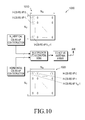
- FIGURE 10 illustrates construction of the horizontal and the vertical CSI-RS APs according to embodiments of the present disclosure.
- the embodiment of the construction 1000 s hown in FIGURE 10 is for illustration only. Other embodiments could be used without departin g from the scope of this disclosure.
- the construction 1000 of the horizontal and the vertical CSI-RS APs includes the N H horizontal CSI-RS APs (say, H-APs 0, ..., N H -1) are transmitted from a row 1005 of the active antenna array, while the N V vertical CSI-RS APs (say, V-APs 0, ..., N V -1) are transmitted from a column 1010 of the active antenna array .
- the horizontal CSI-RS APs are transmitted from the first row 1005 of the antenna array, while the vertical CSI-RS APs are transmitted from the first colu mn 1010 of the antenna array.
- one CS I-RS AP can be shared between the two sets of the CSI-RS APs. For example, only a single CSI-RS signal mapped onto single-port CSI-RS REs is transmitted for H-AP 0 and V-AP 0. Alternati vely, the H-CSI-RS and V-CSI-RS can also be orthogonally and independently mapped in the ti me-frequency grid, even if the two CSI-RS APs are scheduled in the same subframe.
- FIGURE 11 illustrates construction of the horizontal and the vertical CSI-RS APs according to embodiments of the present disclosure.
- the embodiment of the construction 1100 s hown in FIGURE 11 is for illustration only. Other embodiments could be used without departin g from the scope of this disclosure.
- each of the N H horizontal CSI-RS for the N H H-CSI-RS APs (say, H-APs 0, ..., N H -1) are transmitted from a column 1105 of the active antenna array.
- E ach H-CSI-RS signal is precoded with a precoding vector of [p 1 p 2 ... p NV ] t , where the precoding is applied across the antenna elements in each column of the active antenna array.
- each of the N V vertical CSI-RS for the N V APs (say, V-APs 0, ..., N V -1) are transmitted from a row 1110 of the active antenna array.
- Each H-CSI-RS signal is pre coded with a precoding vector of [q 1 q 2 ... q NH ], where the precoding is applied across the anten na elements in each row of the active antenna array.
- the precoding to generate a CSI-RS signal also is referenced as antenna virtualiza tion precoding.
- the construction 1100 can be easily extended to a cons truction in which different precoding vectors are applied across different rows (or columns) corre sponding to the different V-CSI-RS (or H-CSI-RS).
- FIGURE 12 illustrates first and second sets of horizontal CSI-RS APs according t o embodiments of the present disclosure.
- the embodiment of the transmitter chain 1200 includi ng the first and second sets of horizontal CSI-RS APs shown in FIGURE 12 is for illustration onl y. Other embodiments could be used without departing from the scope of the present disclosure.
- two sets of CSI-RS APs 1205, 1210 out of the at least tw o sets of CSI-RS APs are separately constructed: each of the two sets consists of N H H-CSI-RS APs corresponding to a row of antenna elements in the 2D active antenna array 405.
- the tw o sets of H-CSI-RS APs 1205, 1210 are used for UEs' horizontal and vertical CSI estimation.
- the total number of antenna ports at the TP N is separately RRC confi gured from the configurations for the two sets of CSI-RS 1205, 1210.
- FIGURE 13 illustrates construction of two sets of H-CSI-RS APs according to em bodiments of the present disclosure.
- the embodiment of the construction 1300 shown in FIGUR E 13 is for illustration only. Other embodiments could be used without departing from the scope of this disclosure.
- the two rows of antenna elements corresponding to the two sets of H-CSI-RS APs are the first two rows 1305 in the 2D active antenna array 405.
- U E 116 determines the vertical CSI for the entire N H x N V antennas in the 2D active antenna array 405 by estimating the phase difference between the two rows, as well as the horizontal CSI by rel ying on the traditional methods of estimating horizontal CSI.
- the two rows are configurable by t he network, in which case, the network is configured to indicate to each UE at least one of the fol lowing:
- FIGURE 13 is for illustration only. The same idea can be used for constructing N V sets of H-CSI-RS APs corresponding to the N V rows of the 2D antenna array.
- CSI-RS configuration includes a CSI-RS type field to indicate whether the configured CSI-RS is the first H-CSI-RS or the second H-CSI-RS.
- FIGURE 14 illustrates Construction of two sets of H-CSI-RS APs according to e mbodiments of the present disclosure.
- the embodiment of the construction 1400 shown in FIGU RE 14 is for illustration only. Other embodiments could be used without departing from the scop e of this disclosure.
- two different virtualization precoding vectors are applied to the t wo sets of H-CSI-RS APs 1405, 1410.
- Each H-CSI-RS signal in the first set 1405 is precoded wi th a precoding vector of [p 1 p 2 ... p NV ] t
- each H-CSI-RS in the second set is precoded with a precoding vector of [q 1 q 2 ... q NV ] t
- the precoding vector is applied across the antenna ele ments in each column of the active antenna array in each set ofH-CSI-RS APs.
- the UE 116 determi nes the vertical CSI for the entire N H x N V antennas in the 2D active antenna array 405 by estima ting the phase difference between the two sets of H-CSI-RS APs 1405, 1410, as well as the horiz ontal CSI by relying on the traditional methods of estimating horizontal CSI.
- the two virtualizat ion precoding vectors can be indicated by the network to each UE.
- FIGURE 15 illustrates primary and secondary CSI-RS APs according to embodim ents of the present disclosure.
- the embodiment of the transmitter chain 1500 including the prim ary and secondary CSI-RS APs shown in FIGURE 15 is for illustration only. Other embodiment s could be used without departing from the scope of the present disclosure.
- CSI-RS configuration includes a CSI-RS type field, to indicate whether the configured CSI-RS is the primary CSI-RS or the secondary CSI-RS.
- two sets of CSI-RS APs out of the at least two sets of CS I-RS APs are separately constructed and configured (period as well): a set of primary CSI-RS AP s 1505 and a set of secondary CSI-RS APs 1510.
- Primary CSI-RS APs 1505 in certain embodiments, UE 116 utilizes the set of pri mary CSI-RS APs 1505 to derive either H-CSI or V-CSI, depending on whether the primary CSI -RS 1505 are corresponding to the (N H ) horizontally placed antenna elements or (N V ) vertically p laced antenna elements. Whether UE 116 can derive H-CSI or V-CSI out of the primary CSI-RS 1505 is indicated by the network, or fixed in the standard specification (e.g., pre-stored in memo ry 360).
- Secondary CSI-RS APs 1510 in certain embodiments, UE 116 combines the prim ary CSI-RS APs 1505 and the secondary CSI-RS APs 1510 to determine either V-CSI-RS or H-CSI-RS.
- the primary CSI-RS APs 1505 correspond to the horizontally pla ced antenna elements and are used for estimating H-CSI-RS
- the secondary CSI-RS APs 1510, to gether with the primary CSI-RS APs 1505 can be used for estimating the V-CSI-RS.
- the secondary CSI-RS APs 1510 together with the pri mary CSI-RS APs 1505 can be used for estimating the H-CSI-RS.
- the number of secondary APs can be less than the number of the primary APs, and can be separately configured from the num ber of the primary CSI-RS APs 1505.
- the total number of antenna ports at TP N is separately RRC configur ed from the configurations for the two sets of CSI-RS.
- the total number of antenna ports N N H x Nv is used for deriving at least one of joint CQI and joint PMI for the N antenna channels.
- FIGURE 16 illustrates construction of the primary and the secondary CSI-RS acc ording to embodiments of the present disclosure.
- the embodiment of the construction 1600 sho wn in FIGURE 16 is for illustration only. Other embodiments could be used without departing fr om the scope of this disclosure.
- the primary CSI-RS 1605 are H-CSI-RS, while only one AP is provided for the secon dary CSI-RS 1610, which is the first antenna element 1615 of the second row of the 2D active an tenna array 405.
- UE 116 When UE 116 is configured with these primary and secondary CSI-RS, UE 116 derives H-CSI utilizing the primary CSI-RS, and UE 116 derives V-CSI utilizing the primary an d the secondary CSI-RS, such as, by estimating the phase difference between the two types of CS I-RS.
- the relative location of the secondary CSI-RS with respect to the primary CSI-RS can be c onfigured by the network.
- the network is capable of configuring and transmitt ing at least two sets of CSI-RS APs.
- a first set of CSI-RS APs is used for horizontal CSI estimat ion at a first group of UEs, and a second set of CSI-RS APs is used for horizontal CSI estimation at a second group of UEs.
- Each of the at least two sets of CSI-RS APs can be targeted to be best received in a certain distance from the TP (or a certain range of elevation angles). For example, a first set of CSI-RS is best received at distance of 0m to 200m, while the second set of CSI-RS is best receiv ed at distance of 200m to 400 m.
- the network can tailor antenna virtualization precoding method of each set of CSI-RS accordingly.
- the first set of CSI-RS is virtualiz ed with a first virtualization precoding so that it is best received at a first range of distances
- t he second set of CSI-RS is virtualized with a second virtualization precoding so that it is best rec eived at a second range of distances.
- UE 116 can be configured for one set out of the at least two sets of CSI-RS APs b y an RRC configuration. Then, UE 116 estimates horizontal CSI based on the configured set of C SI-RS APs.
- UE 116 can be re-configured to estimate horizontal CSI based on a first set of CSI -RS APs from a second set of CSI-RS APs, by an RRC configuration.
- UE 116 can be configured for the at least two sets of CSI-RS APs.
- UE 116 can es timate and report RSRPs for the at least two sets of CSI-RS APs, e.g., depending on a configured triggering condition.
Landscapes
- Engineering & Computer Science (AREA)
- Signal Processing (AREA)
- Computer Networks & Wireless Communication (AREA)
- Physics & Mathematics (AREA)
- Mathematical Physics (AREA)
- Mobile Radio Communication Systems (AREA)
- Time-Division Multiplex Systems (AREA)
- Radio Transmission System (AREA)
Applications Claiming Priority (3)
| Application Number | Priority Date | Filing Date | Title |
|---|---|---|---|
| US201261618213P | 2012-03-30 | 2012-03-30 | |
| US201261635152P | 2012-04-18 | 2012-04-18 | |
| US13/828,530 US9119209B2 (en) | 2012-03-30 | 2013-03-14 | Apparatus and method for channel-state-information pilot design for an advanced wireless network |
Publications (3)
| Publication Number | Publication Date |
|---|---|
| EP2645616A2 true EP2645616A2 (fr) | 2013-10-02 |
| EP2645616A3 EP2645616A3 (fr) | 2017-04-19 |
| EP2645616B1 EP2645616B1 (fr) | 2020-04-29 |
Family
ID=47998316
Family Applications (1)
| Application Number | Title | Priority Date | Filing Date |
|---|---|---|---|
| EP13161878.7A Active EP2645616B1 (fr) | 2012-03-30 | 2013-03-29 | Appareil et procédé de conception de pilote d'informations d'état d'un canal pour un réseau sans fil avancé |
Country Status (8)
| Country | Link |
|---|---|
| US (3) | US9119209B2 (fr) |
| EP (1) | EP2645616B1 (fr) |
| JP (1) | JP2015518671A (fr) |
| KR (1) | KR102178289B1 (fr) |
| CN (2) | CN107257276B (fr) |
| AU (1) | AU2013240699B2 (fr) |
| RU (1) | RU2619772C2 (fr) |
| WO (1) | WO2013147565A2 (fr) |
Cited By (22)
| Publication number | Priority date | Publication date | Assignee | Title |
|---|---|---|---|---|
| WO2014072796A1 (fr) * | 2012-11-09 | 2014-05-15 | Broadcom Corporation | Procédés et appareil pour transmission sans fil |
| WO2015084051A1 (fr) * | 2013-12-03 | 2015-06-11 | 주식회사 아이티엘 | Procédé de rétroaction de csi, et appareil d'un système d'antennes multiples |
| WO2015093910A1 (fr) * | 2013-12-20 | 2015-06-25 | Samsung Electronics Co., Ltd. | Procédé et dispositif permettant de rapporter des informations d'état de canal |
| WO2015093829A1 (fr) * | 2013-12-17 | 2015-06-25 | 삼성전자 주식회사 | Procédé et appareil de communication dans un système de communication mobile à entrées multiples et sorties multiples de dimension maximale |
| WO2015133690A1 (fr) * | 2014-03-05 | 2015-09-11 | Lg Electronics Inc. | Procédé et appareil pour mesurer une variation de canal pour une formation de faisceau massive basée sur un réseau d'antennes dans un système de communication sans fil |
| WO2015152624A1 (fr) * | 2014-03-31 | 2015-10-08 | Samsung Electronics Co., Ltd. | Appareil et procédé de retour d'informations canal dans un système de communication sans fil |
| EP2879424A4 (fr) * | 2012-08-09 | 2015-11-11 | Zte Corp | Procédé et appareil de mesure de signal pilote |
| WO2015174616A1 (fr) * | 2014-05-15 | 2015-11-19 | Lg Electronics Inc. | Procédé et appareil permettant de calculer des informations de rétroaction de mimo 3d dans un système de communication sans fil |
| WO2015178699A1 (fr) * | 2014-05-22 | 2015-11-26 | Samsung Electronics Co., Ltd. | Procédé et appareil pour générer et transmettre une rétroaction de canal dans un système de communication mobile employant un réseau d'antennes bidimensionnel |
| WO2016013742A1 (fr) * | 2014-07-21 | 2016-01-28 | Lg Electronics Inc. | Procédé et appareil de transmission d'un signal de référence pour une mesure de changement de canal dans un système de communications sans fil |
| WO2016052824A1 (fr) * | 2014-10-01 | 2016-04-07 | 엘지전자 주식회사 | Procédé de configuration de signal de référence pour mimo tridimensionnel dans un système de communication sans fil et appareil pour cela |
| WO2016112867A1 (fr) * | 2015-01-16 | 2016-07-21 | 华为技术有限公司 | Procédé de compte rendu d'informations d'état de canal, équipement d'utilisateur et système |
| CN105874835A (zh) * | 2014-01-28 | 2016-08-17 | 富士通株式会社 | 信息配置方法、信息配置装置和通信系统 |
| TWI566541B (zh) * | 2014-02-21 | 2017-01-11 | 電信科學技術研究院 | Channel state information measurement method and apparatus, and signal transmission method and apparatus |
| EP3111598A4 (fr) * | 2014-02-27 | 2017-11-01 | Nokia Solutions and Networks Oy | Procédé et appareil pour le signalement flexible d'un livre de codes de produit |
| CN107852301A (zh) * | 2015-07-10 | 2018-03-27 | Lg 电子株式会社 | 在无线通信系统中报告信道状态信息的方法及其设备 |
| US10039104B2 (en) | 2015-08-14 | 2018-07-31 | Industrial Technology Research Institute | Dynamic beamforming method and related apparatuses using the same |
| WO2018188669A1 (fr) | 2017-04-14 | 2018-10-18 | Mediatek Inc. | Mappage de couches, rétroaction de csi et rétroaction harq dans des communications mobiles |
| CN109155646A (zh) * | 2016-05-12 | 2019-01-04 | 华为技术有限公司 | 通信方法、用户设备和基站 |
| CN109792360A (zh) * | 2016-09-30 | 2019-05-21 | 瑞典爱立信有限公司 | Mimo的基于cdm8的csi-rs设计 |
| CN110635883A (zh) * | 2018-06-25 | 2019-12-31 | 中兴通讯股份有限公司 | 信息反馈方法及装置,存储介质,电子装置 |
| US10965410B2 (en) | 2013-12-17 | 2021-03-30 | Samsung Electronics Co., Ltd. | Communication method and apparatus in full-dimensional multiple-input multiple-output mobile communication system |
Families Citing this family (107)
| Publication number | Priority date | Publication date | Assignee | Title |
|---|---|---|---|---|
| CN107104781B (zh) * | 2012-02-11 | 2020-06-05 | Lg电子株式会社 | 接收和发送下行链路数据信道的方法及设备 |
| US9059878B2 (en) | 2012-03-30 | 2015-06-16 | Nokia Solutions And Networks Oy | Codebook feedback method for per-user elevation beamforming |
| US9161241B2 (en) * | 2012-03-30 | 2015-10-13 | Nokia Solutions And Networks Oy | Reference signal design and signaling for per-user elevation MIMO |
| AU2013250063B2 (en) * | 2012-04-19 | 2017-11-02 | Samsung Electronics Co., Ltd. | Method and apparatus for quasi co-location identification of reference symbol ports for coordinated multi-point communication systems |
| US8874103B2 (en) | 2012-05-11 | 2014-10-28 | Intel Corporation | Determining proximity of user equipment for device-to-device communication |
| US9083479B2 (en) * | 2012-05-11 | 2015-07-14 | Intel Corporation | Signaling for downlink coordinated multipoint in a wireless communication system |
| US9397738B2 (en) * | 2012-05-17 | 2016-07-19 | Qualcomm Incorporated | Codebook and feedback design for high order MIMO |
| US9794817B2 (en) | 2012-06-24 | 2017-10-17 | Lg Electronics Inc. | Method and apparatus for reporting channel state information in wireless communication system |
| US9621316B2 (en) | 2012-07-03 | 2017-04-11 | Lg Electronics Inc. | Method and device for receiving downlink signal in wireless communication system |
| US9735933B2 (en) * | 2012-07-09 | 2017-08-15 | Lg Electronics Inc. | Method for receiving or transmitting downlink signal in wireless communication system and device therefor |
| US8885752B2 (en) * | 2012-07-27 | 2014-11-11 | Intel Corporation | Method and apparatus for feedback in 3D MIMO wireless systems |
| US9473227B2 (en) * | 2012-08-26 | 2016-10-18 | Lg Electronics Inc. | Method and apparatus for transmitting codebook-based signal in wireless communication system |
| CN103780332B (zh) * | 2012-10-19 | 2017-03-29 | 电信科学技术研究院 | 传输编码指示信息和确定预编码矩阵的方法、系统及设备 |
| WO2014065600A1 (fr) * | 2012-10-24 | 2014-05-01 | Samsung Electronics Co., Ltd. | Procédé et appareil pour transmettre et recevoir des informations de canal commun dans un système de communication sans fil |
| USRE49578E1 (en) * | 2012-10-24 | 2023-07-11 | Samsung Electronics Co., Ltd | Method and apparatus for transmitting and receiving common channel information in wireless communication system |
| KR101987232B1 (ko) * | 2012-11-02 | 2019-09-30 | 주식회사 팬택 | 다중 안테나 시스템에서 참조 신호의 전송장치 및 방법 |
| WO2014088003A1 (fr) * | 2012-12-06 | 2014-06-12 | シャープ株式会社 | Appareil formant station de base, appareil formant terminal, système de communication sans fil, et circuit intégré |
| WO2014107136A1 (fr) * | 2013-01-04 | 2014-07-10 | Telefonaktiebolaget L M Ericsson (Publ) | Procédé d'estimation du décalage de fréquence en utilisant des signaux de référence occupant quasiment la même position |
| US9768898B2 (en) * | 2013-01-18 | 2017-09-19 | Lg Electronics Inc. | Method for reception in cooperative transmission environment and terminal |
| EP2950458A4 (fr) * | 2013-01-28 | 2016-11-16 | Fujitsu Ltd | Procédé de renvoi d'informations d'état de canal, procédé d'émission d'un signal de référence d'informations d'état de canal, équipement d'utilisateur et station de base |
| WO2014142504A1 (fr) * | 2013-03-11 | 2014-09-18 | 엘지전자 주식회사 | Procédé et appareil de rapport d'informations d'état de canal dans un système de communication sans fil |
| US9544112B2 (en) * | 2013-03-19 | 2017-01-10 | Lg Electronics Inc. | Method by which terminal transmits and receives signal in multi cell-based wireless communication system, and device for same |
| US10193665B2 (en) * | 2013-03-21 | 2019-01-29 | Texas Instruments Incorporated | Reference signal for 3D MIMO in wireless communication systems |
| CN105191164B (zh) * | 2013-04-02 | 2020-06-09 | 太阳专利托管公司 | 将csi-rs端口映射于天线单元的方法以及基站 |
| EP2961215B1 (fr) * | 2013-04-03 | 2017-03-29 | Huawei Technologies Co., Ltd. | Procédés et appareil pour recevoir et envoyer un signal de référence, équipement utilisateur et station de base |
| GB2512634A (en) | 2013-04-04 | 2014-10-08 | Nec Corp | Communication system |
| JP2014204305A (ja) * | 2013-04-05 | 2014-10-27 | 株式会社Nttドコモ | 無線通信システム、無線基地局装置、およびユーザ装置 |
| US9831932B2 (en) * | 2013-05-01 | 2017-11-28 | Lg Electronics Inc. | Method for transmitting feedback information through terminal to for split beamforming in wireless communication system and apparatus therefor |
| US9271279B2 (en) * | 2013-05-09 | 2016-02-23 | Sharp Laboratories Of America, Inc. | Channel state measurement and reporting |
| KR102064939B1 (ko) * | 2013-08-07 | 2020-01-13 | 삼성전자 주식회사 | 다수의 이차원 배열 안테나를 사용하는 이동통신 시스템에서의 피드백 송수신 방법 및 장치 |
| WO2015042870A1 (fr) | 2013-09-27 | 2015-04-02 | Qualcomm Incorporated | Création de rapport de csi pour fonction eimta lte-tdd |
| EP3058667B1 (fr) | 2013-10-18 | 2023-03-29 | Qualcomm Incorporated | Procédé et appareil de configuration de csi-rs pour mimo 3d |
| WO2015074262A1 (fr) * | 2013-11-22 | 2015-05-28 | 华为技术有限公司 | Procédé et appareil de renvoi d'informations d'état de canal |
| CN105052187B (zh) | 2013-12-16 | 2020-03-20 | 华为技术有限公司 | 导频信号的传输方法、基站及用户设备 |
| WO2015096143A1 (fr) * | 2013-12-27 | 2015-07-02 | 华为技术有限公司 | Procédé et dispositif de transmission pour transmettre des informations d'état de canal |
| CN105027458B (zh) * | 2013-12-31 | 2018-11-30 | 华为技术有限公司 | 一种信道信息获取的方法、装置及系统 |
| CN104767592B (zh) * | 2014-01-02 | 2019-01-01 | 中国移动通信集团公司 | 一种csi-rs的端口配置、csi-rs传输的方法和设备 |
| US9787376B2 (en) | 2014-01-06 | 2017-10-10 | Intel IP Corporation | Systems, methods, and devices for hybrid full-dimensional multiple-input multiple-output |
| US20170005712A1 (en) * | 2014-01-22 | 2017-01-05 | Nec Corporation | Method and apparatus for channel measurement and feedback |
| US10020920B2 (en) | 2014-03-04 | 2018-07-10 | Lg Electronics Inc. | Method for transmitting enhanced reference signal in multi-antenna wireless communication system and apparatus therefor |
| US10256884B2 (en) * | 2014-03-06 | 2019-04-09 | Alcatel Lucent | Method and apparatus for quantizing channel state information |
| JP6121931B2 (ja) * | 2014-03-20 | 2017-04-26 | 株式会社Nttドコモ | 移動通信システム、基地局、およびユーザ装置 |
| US20150288499A1 (en) * | 2014-04-07 | 2015-10-08 | Samsung Electronics Co., Ltd. | Periodic and aperiodic channel state information reporting for advanced wireless communication systems |
| US10224993B2 (en) * | 2014-05-02 | 2019-03-05 | Lg Electronics Inc. | Beamforming method in multi-antenna wireless communication system and apparatus for same |
| US9755719B2 (en) * | 2014-06-12 | 2017-09-05 | Lg Electronics Inc. | Method for configuring codebook in multi-antenna wireless communication system and device therefor |
| CN105262520B (zh) * | 2014-07-18 | 2018-07-27 | 上海诺基亚贝尔股份有限公司 | 一种调整有源天线阵列及参考信号映射的方法和装置 |
| KR102014797B1 (ko) * | 2014-07-23 | 2019-08-27 | 엘지전자 주식회사 | 무선 접속 시스템에서 채널상태정보를 전송하는 방법 및 장치 |
| US10033507B2 (en) | 2014-07-28 | 2018-07-24 | Lg Electronics Inc. | Method for performing channel estimation, and apparatus therefor |
| US10355763B2 (en) | 2014-07-31 | 2019-07-16 | Lg Electronics Inc. | Method for estimating channel and device therefor |
| KR102333401B1 (ko) * | 2014-08-01 | 2021-11-30 | 엘지전자 주식회사 | 채널 상태 보고를 위한 방법 및 이를 위한 장치 |
| WO2016021013A1 (fr) * | 2014-08-06 | 2016-02-11 | 富士通株式会社 | Système de communication sans fil, station de base, station mobile, procédé d'émission et procédé d'estimation |
| WO2016021012A1 (fr) * | 2014-08-06 | 2016-02-11 | 富士通株式会社 | Système de communication sans fil, station de base, station mobile, procédé d'émission et procédé de démodulation |
| WO2016036205A2 (fr) * | 2014-09-04 | 2016-03-10 | 삼성전자주식회사 | Dispositif et procédé de transmission d'informations de rétroaction dans un système de communication sans fil |
| KR102487525B1 (ko) | 2014-09-04 | 2023-01-12 | 삼성전자주식회사 | 무선 통신 시스템에서 피드백 정보 송신을 위한 장치 및 방법 |
| US20160072562A1 (en) * | 2014-09-10 | 2016-03-10 | Samsung Electronics Co., Ltd. | Channel state information reporting with basis expansion for advanced wireless communications systems |
| US9537552B2 (en) * | 2014-09-12 | 2017-01-03 | Samsung Electronics Co., Ltd. | Method and apparatus for channel state information based on antenna mapping and subsampling |
| CN105515729B (zh) * | 2014-09-26 | 2019-01-11 | 上海诺基亚贝尔股份有限公司 | 一种用于实施fd-mimo的方法、设备与系统 |
| US10135508B2 (en) * | 2014-10-13 | 2018-11-20 | Electronics And Telecommunications Research Institute | Method and apparatus for generating common signal in multiple input multiple output system |
| JP2017228813A (ja) * | 2014-11-06 | 2017-12-28 | シャープ株式会社 | 基地局装置、端末装置および通信方法 |
| US10476563B2 (en) | 2014-11-06 | 2019-11-12 | Futurewei Technologies, Inc. | System and method for beam-formed channel state reference signals |
| JP6649268B2 (ja) * | 2014-11-06 | 2020-02-19 | シャープ株式会社 | 基地局装置、端末装置および通信方法 |
| US10225054B2 (en) | 2014-11-07 | 2019-03-05 | Electronics And Telecommunications Research Institute | Method and apparatus for transmitting reference signal, method and apparatus for measuring and reporting channel state information, and method for configuring the same |
| WO2016074119A1 (fr) * | 2014-11-10 | 2016-05-19 | Qualcomm Incorporated | Rapport de pmi d'élévation sur pucch |
| US10014916B2 (en) | 2014-11-10 | 2018-07-03 | Samsung Electronics Co., Ltd. | 2D active antenna array operation for wireless communication systems |
| WO2016076657A1 (fr) * | 2014-11-13 | 2016-05-19 | 엘지전자 주식회사 | Procédé de transmission de signal de référence dans un système de communication sans fil multi-antenne, et dispositif associé |
| US10020860B2 (en) * | 2014-12-02 | 2018-07-10 | Samsung Electronics Co., Ltd. | Downlink signaling for partially precoded CSI-RS and CSI feedback |
| US9621243B2 (en) | 2014-12-03 | 2017-04-11 | Texas Instruments Incorporated | Method and apparatus for CSI feedback in a MIMO wireless communication system with elevation beamforming |
| CN107211486B (zh) * | 2014-12-31 | 2020-09-08 | 华为技术有限公司 | 一种预编码矩阵指示pmi的反馈方法 |
| EP3471307B1 (fr) | 2015-01-19 | 2026-02-18 | QUALCOMM Incorporated | Réduction du surdébit de retour d'informations de csi pour systèmes fd-mimo |
| WO2016122761A1 (fr) * | 2015-01-26 | 2016-08-04 | Intel IP Corporation | Dispositif et procédé pour améliorer la précision de positionnement horizontal et vertical |
| CA2974948A1 (fr) * | 2015-01-29 | 2016-08-04 | Sony Corporation | Dispositif et procede |
| US9900198B2 (en) * | 2015-02-20 | 2018-02-20 | Samsung Electronics Co., Ltd. | Channel-state-information reference signals for advanced wireless systems |
| WO2016153112A1 (fr) * | 2015-03-20 | 2016-09-29 | 엘지전자 주식회사 | Procédé de génération d'informations d'état de canal pour entrées multiples et sorties multiples (mimo) tridimensionnelles dans un système de communication sans fil, et dispositif associé |
| US10312975B2 (en) * | 2015-03-24 | 2019-06-04 | Sony Corporation | Apparatus |
| CN107567695B (zh) * | 2015-03-27 | 2021-02-02 | 三星电子株式会社 | 大规模天线系统中的资源分配设备和方法 |
| US10110286B2 (en) | 2015-03-30 | 2018-10-23 | Samsung Electronics Co., Ltd. | Method and apparatus for codebook design and signaling |
| CN106160823B (zh) * | 2015-04-03 | 2021-02-05 | 索尼公司 | 用于无线通信的装置和方法 |
| KR102378517B1 (ko) | 2015-04-09 | 2022-03-24 | 삼성전자주식회사 | 다중 안테나를 이용하는 무선 통신 시스템에서 송신 전력 제어 방법 및 장치 |
| ES2764390T3 (es) * | 2015-04-10 | 2020-06-03 | Huawei Tech Co Ltd | Método y dispositivo de transmisión de datos |
| CN106160810A (zh) * | 2015-04-13 | 2016-11-23 | 北京信威通信技术股份有限公司 | 一种二维多输入多输出系统的预编码方法 |
| CN104967471B (zh) * | 2015-05-06 | 2018-01-05 | 西安交通大学 | 一种全维度 mimo 系统中的信道反馈方法 |
| US10574486B2 (en) | 2015-06-07 | 2020-02-25 | Lg Electronics Inc. | Channel measurement method in wireless communication system and apparatus therefor |
| US9641229B2 (en) * | 2015-06-30 | 2017-05-02 | Motorola Mobility Llc | Method and system for a reconfigurable over-indexed antenna array |
| WO2017007240A1 (fr) * | 2015-07-06 | 2017-01-12 | 삼성전자 주식회사 | Procédé et appareil pour mesurer un canal dans un système de communication mobile |
| US10219169B1 (en) * | 2015-07-09 | 2019-02-26 | Quantenna Communications, Inc. | Hybrid MU-MIMO spatial mapping using both explicit sounding and crosstalk tracking in a wireless local area network |
| KR102405408B1 (ko) * | 2015-07-16 | 2022-06-07 | 삼성전자 주식회사 | 전차원 다중 입출력 시스템에서 채널 상태 정보를 송수신하는 방법 및 장치 |
| US10211964B2 (en) | 2015-07-29 | 2019-02-19 | Samsung Electronics Co., Ltd. | Method and apparatus for CSI reporting |
| WO2017028006A1 (fr) * | 2015-08-14 | 2017-02-23 | Qualcomm Incorporated | Techniques permettant d'émettre et recevoir des signaux de référence d'informations d'état de canal dans un environnement ebf/fd-mimo |
| US10103857B2 (en) * | 2015-09-16 | 2018-10-16 | Samsung Electronics Co., Ltd. | Signaling methods and apparatus for advanced MIMO communication systems |
| EP3379747A4 (fr) * | 2015-11-17 | 2018-11-14 | Sony Corporation | Dispositif terminal, dispositif de communication par radio et procédé de communication |
| CN107204794B (zh) * | 2016-03-18 | 2020-02-21 | 电信科学技术研究院 | 一种csi反馈方法及装置 |
| CN109076505B (zh) | 2016-03-30 | 2024-08-06 | 日本电气株式会社 | 用于传输和接收参考信号的方法和装置 |
| JP6969633B2 (ja) * | 2016-03-30 | 2021-11-24 | 日本電気株式会社 | 基地局およびueによって実行される方法 |
| DK3455988T3 (da) | 2016-05-13 | 2021-06-21 | Ericsson Telefon Ab L M | CSI-feedback med flere opløsninger |
| CN109891767A (zh) * | 2016-11-26 | 2019-06-14 | 华为技术有限公司 | 一种确定预编码矩阵的方法、装置及系统 |
| US11888570B2 (en) * | 2017-03-23 | 2024-01-30 | Ntt Docomo, Inc. | User terminal and radio communication method |
| WO2018174803A1 (fr) * | 2017-03-24 | 2018-09-27 | Telefonaktiebolaget Lm Ericsson (Publ) | Systèmes et procédés pour déterminer des configurations d'émetteur et de récepteur pour un dispositif sans fil |
| CN115664615B (zh) | 2017-03-24 | 2025-04-25 | 中兴通讯股份有限公司 | 信道状态信息导频的接收方法和装置、以及存储介质 |
| US20180287860A1 (en) | 2017-03-31 | 2018-10-04 | Futurewei Technologies, Inc. | System and Method for Communications Beam Recovery |
| WO2019103580A1 (fr) * | 2017-11-27 | 2019-05-31 | 엘지전자 주식회사 | Procédé de mise en œuvre de notification de csi dans un système de communication sans fil, et appareil correspondant |
| JP6536976B2 (ja) * | 2018-01-11 | 2019-07-03 | サン パテント トラスト | 端末および通信方法 |
| CN110035484A (zh) | 2018-01-12 | 2019-07-19 | 中兴通讯股份有限公司 | 一种功率控制方法、第一通信节点和第二通信节点 |
| EP3637629B1 (fr) | 2018-01-19 | 2021-04-14 | Guangdong Oppo Mobile Telecommunications Corp., Ltd. | Procédé de mesure d'informations d'état de canal (csi), dispositif de terminal et dispositif de réseau |
| JP6865378B2 (ja) * | 2019-05-22 | 2021-04-28 | サン パテント トラスト | 基地局装置および通信方法 |
| JP7189850B2 (ja) * | 2019-08-14 | 2022-12-14 | 富士通株式会社 | 情報構成方法、情報構成装置及び通信システム |
| CN114982146B (zh) * | 2020-02-07 | 2025-11-14 | 华为技术有限公司 | 信号发送方法及装置 |
| WO2022153458A1 (fr) * | 2021-01-14 | 2022-07-21 | 株式会社Nttドコモ | Terminal, procédé de communication sans fil et station de base |
Family Cites Families (50)
| Publication number | Priority date | Publication date | Assignee | Title |
|---|---|---|---|---|
| KR0168797B1 (ko) * | 1996-04-02 | 1999-02-01 | 김광호 | 기지국 송신기의 동시 송출 제어장치 |
| US6584144B2 (en) * | 1997-02-24 | 2003-06-24 | At&T Wireless Services, Inc. | Vertical adaptive antenna array for a discrete multitone spread spectrum communications system |
| US6950678B1 (en) * | 2000-05-24 | 2005-09-27 | Lucent Technologies Inc. | Control technique for a communication system |
| US6785341B2 (en) * | 2001-05-11 | 2004-08-31 | Qualcomm Incorporated | Method and apparatus for processing data in a multiple-input multiple-output (MIMO) communication system utilizing channel state information |
| KR20120024992A (ko) * | 2003-04-23 | 2012-03-14 | 콸콤 인코포레이티드 | 무선 통신 시스템에서 수행성능을 향상시키는 방법들 및 장치 |
| US20050272472A1 (en) * | 2004-05-27 | 2005-12-08 | Interdigital Technology Corporation | Wireless communication method and system for forming three-dimensional control channel beams and managing high volume user coverage areas |
| US7362269B2 (en) * | 2004-09-23 | 2008-04-22 | Interdigital Technology Corporation | Undulating transmit patterns to support signal separation at a receiver |
| JP2006135426A (ja) * | 2004-11-02 | 2006-05-25 | Denso Corp | 路車間通信システム及びその基地局及び指向性可変アンテナ |
| CN101185200B (zh) * | 2005-11-14 | 2011-07-20 | 桥扬科技有限公司 | 用于蜂窝通信和广播的多天线系统 |
| CN103441339B (zh) * | 2006-04-27 | 2016-01-13 | 泰科电子服务有限责任公司 | 异向材料天线设备 |
| RU2437252C2 (ru) | 2006-11-07 | 2011-12-20 | Квэлкомм Инкорпорейтед | Способ и устройство для поддержки широковещательных передач в неактивных областях мультивещательной/широковещательной сети с одной частотой (mbsfn) |
| US20110038272A1 (en) | 2007-12-31 | 2011-02-17 | Zion Hadad | Generalized eesm system and method |
| US9402247B2 (en) * | 2008-10-20 | 2016-07-26 | Interdigital Patent Holdings, Inc. | Uplink control information transmission methods for carrier aggregation |
| EP2660991B1 (fr) | 2009-01-07 | 2020-07-29 | Sun Patent Trust | Appareil et procédé de communication sans fil |
| KR20100138261A (ko) | 2009-06-24 | 2010-12-31 | 주식회사 팬택 | 무선통신 시스템에서 참조신호의 할당방법 및 그 장치, 그 장치를 이용한 송수신장치 |
| KR101753585B1 (ko) | 2009-08-14 | 2017-07-04 | 엘지전자 주식회사 | 다중 안테나를 지원하는 무선 통신 시스템에서 하향링크 참조신호를 전송하는 방법 및 장치 |
| KR101740221B1 (ko) * | 2010-01-18 | 2017-05-29 | 주식회사 골드피크이노베이션즈 | 채널상태정보-기준신호 할당 방법 및 장치 |
| KR101241916B1 (ko) | 2010-02-07 | 2013-03-11 | 엘지전자 주식회사 | 다중 안테나를 지원하는 무선 통신 시스템에서 하향링크 참조신호를 전송하는 방법 및 장치 |
| US9407409B2 (en) * | 2010-02-23 | 2016-08-02 | Qualcomm Incorporated | Channel state information reference signals |
| WO2011115421A2 (fr) | 2010-03-17 | 2011-09-22 | Lg Electronics Inc. | Procédé et appareil permettant d'obtenir des informations de configuration de signal de référence d'informations d'état de canal (csi-rs) dans un système de communication sans fil supportant de multiples antennes |
| KR101719542B1 (ko) | 2010-08-13 | 2017-03-27 | 주식회사 팬택 | 뮤팅 정보 전송 장치 및 방법과, 그를 이용한 채널 상태 획득 장치 및 방법 |
| US8780766B2 (en) * | 2010-08-16 | 2014-07-15 | Qualcomm Incorporated | Interleaving for relay physical downlink control channel (R-PDCCH) |
| KR20120029338A (ko) | 2010-09-16 | 2012-03-26 | 엘지전자 주식회사 | 다중 안테나 지원 무선 통신 시스템에서 효율적인 피드백 방법 및 장치 |
| US8681651B2 (en) * | 2010-11-05 | 2014-03-25 | Qualcomm Incorporated | Reference signal reception and channel state information determination for multiple nodes in a wireless communication network |
| KR20120063586A (ko) * | 2010-12-08 | 2012-06-18 | 삼성전자주식회사 | 분산 안테나를 적용하는 이동 통신 시스템에서 채널상태 정보 송수신 방법 및 장치 |
| US9252930B2 (en) * | 2011-01-07 | 2016-02-02 | Futurewei Technologies, Inc. | Reference signal transmission and reception method and equipment |
| KR101777424B1 (ko) * | 2011-01-19 | 2017-09-12 | 엘지전자 주식회사 | 다중 노드 시스템에서 신호 수신 방법 및 장치 |
| US20120208541A1 (en) * | 2011-02-14 | 2012-08-16 | Qualcomm Incorporated | Mobility procedures in wireless networks with distributed remote radio heads |
| US9559820B2 (en) * | 2011-02-18 | 2017-01-31 | Qualcomm Incorporated | Feedback reporting based on channel state information reference signal (CSI-RS) groups |
| US8675762B2 (en) * | 2011-05-02 | 2014-03-18 | Alcatel Lucent | Method of transforming pre-coded signals for multiple-in-multiple-out wireless communication |
| US9319123B2 (en) * | 2011-05-10 | 2016-04-19 | Lg Electronics Inc. | Method for receiving reference signal and user equipment, and method for transmitting reference signal and base station |
| CN103597753B (zh) * | 2011-05-13 | 2017-02-15 | Lg电子株式会社 | 在无线通信系统中基于csi‑rs的信道评估方法及其装置 |
| KR20140036247A (ko) * | 2011-06-29 | 2014-03-25 | 엘지전자 주식회사 | 채널상태정보 전송방법 및 사용자 기기, 그리고 채널상태정보 수신방법 및 기지국 |
| US20130010880A1 (en) * | 2011-07-05 | 2013-01-10 | Renesas Mobile Corporation | Feedback Framework for MIMO Operation in Heterogeneous Communication Network |
| CN102255689B (zh) * | 2011-07-08 | 2018-05-04 | 中兴通讯股份有限公司 | 一种信道状态信息的处理方法、装置及系统 |
| US20130051321A1 (en) * | 2011-08-24 | 2013-02-28 | Qualcomm Incorporated | Multiple description coding (mdc) for channel state information reference signals (csi-rs) |
| WO2013042987A2 (fr) * | 2011-09-23 | 2013-03-28 | 엘지전자 주식회사 | Procédé et appareil de retour d'informations de canal dans un système de communication sans fil |
| US9144045B2 (en) * | 2011-10-06 | 2015-09-22 | Telefonaktiebolaget L M Ericsson (Publ) | Time and frequency synchronization |
| WO2013070577A1 (fr) * | 2011-11-07 | 2013-05-16 | Motorola Mobility Llc | Procédé et appareil de renvoi de données d'état de canal (csi) pour schémas combinés de traitement dans un système de communication à multiplexage par répartition orthogonale en fréquence avec transmission multipoint coordonnée |
| US8885569B2 (en) * | 2011-12-19 | 2014-11-11 | Ofinno Technologies, Llc | Beamforming signaling in a wireless network |
| US9215694B2 (en) * | 2011-12-22 | 2015-12-15 | Qualcomm Incorporated | Reference signals design for time tracking in LTE-A |
| JP6006335B2 (ja) * | 2012-02-11 | 2016-10-12 | エルジー エレクトロニクス インコーポレイティド | チャネル状態情報を報告するための方法、これをサポートする方法、及びこれらの方法のための装置 |
| US9635658B2 (en) * | 2012-02-27 | 2017-04-25 | Samsung Electronics Co., Ltd. | Adaptation of control signaling transmissions to variations in respective resources |
| EP2820772B1 (fr) * | 2012-03-02 | 2019-11-20 | Telefonaktiebolaget LM Ericsson (publ) | Station de base radio et procédé à l'intérieur de cette dernière permettant de transmettre un signal de données à un équipement utilisateur se trouvant dans un réseau de radiocommunication |
| KR101611328B1 (ko) * | 2012-03-06 | 2016-04-26 | 엘지전자 주식회사 | 무선 통신 시스템에서 채널상태정보 전송 방법 및 장치 |
| US20130328722A1 (en) * | 2012-03-06 | 2013-12-12 | Niklas Wernersson | Node and method for establishing beamforming for downlink communications |
| WO2013137794A1 (fr) * | 2012-03-15 | 2013-09-19 | Telefonaktiebolaget L M Ericsson (Publ) | Nœud et procédé de génération de signaux en forme de faisceau pour une communication en liaison descendante |
| GB2500391B (en) * | 2012-03-19 | 2014-10-22 | Broadcom Corp | Method and apparatus for providing feedback in multipoint transmissions |
| WO2013144361A1 (fr) * | 2012-03-30 | 2013-10-03 | Nokia Siemens Networks Oy | Méthodologie de rétroaction pour mimo par élévation d'utilisateur |
| US9161241B2 (en) * | 2012-03-30 | 2015-10-13 | Nokia Solutions And Networks Oy | Reference signal design and signaling for per-user elevation MIMO |
-
2013
- 2013-03-14 US US13/828,530 patent/US9119209B2/en not_active Ceased
- 2013-03-29 EP EP13161878.7A patent/EP2645616B1/fr active Active
- 2013-04-01 CN CN201710650599.7A patent/CN107257276B/zh active Active
- 2013-04-01 AU AU2013240699A patent/AU2013240699B2/en active Active
- 2013-04-01 CN CN201380017577.7A patent/CN104205660B/zh not_active Expired - Fee Related
- 2013-04-01 WO PCT/KR2013/002688 patent/WO2013147565A2/fr not_active Ceased
- 2013-04-01 KR KR1020147030680A patent/KR102178289B1/ko active Active
- 2013-04-01 JP JP2015503128A patent/JP2015518671A/ja active Pending
- 2013-04-01 RU RU2014143812A patent/RU2619772C2/ru active
-
2017
- 2017-02-01 US US15/422,408 patent/USRE47879E1/en active Active
-
2020
- 2020-02-04 US US16/781,836 patent/USRE50379E1/en active Active
Cited By (66)
| Publication number | Priority date | Publication date | Assignee | Title |
|---|---|---|---|---|
| US9510221B2 (en) | 2012-08-09 | 2016-11-29 | Zte Corporation | Methods and apparatuses for measuring pilot |
| EP2879424A4 (fr) * | 2012-08-09 | 2015-11-11 | Zte Corp | Procédé et appareil de mesure de signal pilote |
| WO2014072796A1 (fr) * | 2012-11-09 | 2014-05-15 | Broadcom Corporation | Procédés et appareil pour transmission sans fil |
| WO2015084051A1 (fr) * | 2013-12-03 | 2015-06-11 | 주식회사 아이티엘 | Procédé de rétroaction de csi, et appareil d'un système d'antennes multiples |
| KR20150064383A (ko) * | 2013-12-03 | 2015-06-11 | 주식회사 아이티엘 | 다중 안테나 시스템에서 csi 피드백 방법 및 장치 |
| WO2015093829A1 (fr) * | 2013-12-17 | 2015-06-25 | 삼성전자 주식회사 | Procédé et appareil de communication dans un système de communication mobile à entrées multiples et sorties multiples de dimension maximale |
| US10965410B2 (en) | 2013-12-17 | 2021-03-30 | Samsung Electronics Co., Ltd. | Communication method and apparatus in full-dimensional multiple-input multiple-output mobile communication system |
| US11750340B2 (en) | 2013-12-17 | 2023-09-05 | Samsung Electronics Co., Ltd. | Communication method and apparatus in full-dimensional multiple-input multiple-output mobile communication system |
| WO2015093910A1 (fr) * | 2013-12-20 | 2015-06-25 | Samsung Electronics Co., Ltd. | Procédé et dispositif permettant de rapporter des informations d'état de canal |
| CN110545134A (zh) * | 2013-12-20 | 2019-12-06 | 北京三星通信技术研究有限公司 | 信道状态信息汇报的方法及装置 |
| US10111112B2 (en) | 2013-12-20 | 2018-10-23 | Samsung Electronics Co., Ltd. | Method and device for reporting channel state information |
| CN110545133B (zh) * | 2013-12-20 | 2022-12-06 | 北京三星通信技术研究有限公司 | 信道状态信息汇报的方法及装置 |
| CN110545134B (zh) * | 2013-12-20 | 2022-10-21 | 北京三星通信技术研究有限公司 | 信道状态信息汇报的方法及装置 |
| CN110545133A (zh) * | 2013-12-20 | 2019-12-06 | 北京三星通信技术研究有限公司 | 信道状态信息汇报的方法及装置 |
| EP3101932A4 (fr) * | 2014-01-28 | 2017-09-20 | Fujitsu Limited | Procédé de configuration d'informations, dispositif de configuration d'informations et système de communications |
| CN105874835B (zh) * | 2014-01-28 | 2020-07-24 | 富士通株式会社 | 信息配置方法、信息配置装置和通信系统 |
| US10567968B2 (en) | 2014-01-28 | 2020-02-18 | Fujitsu Limited | Information configuration method, information configuration apparatus and communication system |
| CN105874835A (zh) * | 2014-01-28 | 2016-08-17 | 富士通株式会社 | 信息配置方法、信息配置装置和通信系统 |
| US11477657B2 (en) | 2014-01-28 | 2022-10-18 | Fujitsu Limited | Information configuration method, information configuration apparatus and communication system |
| TWI566541B (zh) * | 2014-02-21 | 2017-01-11 | 電信科學技術研究院 | Channel state information measurement method and apparatus, and signal transmission method and apparatus |
| EP3111598A4 (fr) * | 2014-02-27 | 2017-11-01 | Nokia Solutions and Networks Oy | Procédé et appareil pour le signalement flexible d'un livre de codes de produit |
| CN105940615B (zh) * | 2014-03-05 | 2019-07-09 | Lg电子株式会社 | 用于在无线通信系统中测量基于大规模天线阵列的波束成形的信道变化的方法和设备 |
| US9800314B2 (en) | 2014-03-05 | 2017-10-24 | Lg Electronics Inc. | Method and apparatus for measuring channel variation for massive antenna array based beamforming in wireless communication system |
| CN105940615A (zh) * | 2014-03-05 | 2016-09-14 | Lg电子株式会社 | 用于在无线通信系统中测量基于大规模天线阵列的波束成形的信道变化的方法和设备 |
| WO2015133690A1 (fr) * | 2014-03-05 | 2015-09-11 | Lg Electronics Inc. | Procédé et appareil pour mesurer une variation de canal pour une formation de faisceau massive basée sur un réseau d'antennes dans un système de communication sans fil |
| US9667328B2 (en) | 2014-03-31 | 2017-05-30 | Samsung Electronics Co., Ltd. | Precoding matrix codebook design and periodic channel state information feedback for advanced wireless communication systems |
| WO2015152624A1 (fr) * | 2014-03-31 | 2015-10-08 | Samsung Electronics Co., Ltd. | Appareil et procédé de retour d'informations canal dans un système de communication sans fil |
| CN106233640A (zh) * | 2014-03-31 | 2016-12-14 | 三星电子株式会社 | 无线通信系统中用于信道信息反馈的装置和方法 |
| CN106233640B (zh) * | 2014-03-31 | 2020-08-07 | 三星电子株式会社 | 无线通信系统中用于信道信息反馈的装置和方法 |
| CN106464319A (zh) * | 2014-05-15 | 2017-02-22 | Lg电子株式会社 | 在无线通信系统中针对3d mimo计算反馈信息的方法和设备 |
| EP3143704A4 (fr) * | 2014-05-15 | 2018-01-03 | LG Electronics Inc. | Procédé et appareil permettant de calculer des informations de rétroaction de mimo 3d dans un système de communication sans fil |
| WO2015174616A1 (fr) * | 2014-05-15 | 2015-11-19 | Lg Electronics Inc. | Procédé et appareil permettant de calculer des informations de rétroaction de mimo 3d dans un système de communication sans fil |
| CN106464319B (zh) * | 2014-05-15 | 2019-09-24 | Lg电子株式会社 | 在无线通信系统中针对3d mimo计算反馈信息的方法和设备 |
| US9806780B2 (en) | 2014-05-22 | 2017-10-31 | Samsung Electronics Co., Ltd | Method and apparatus for generating and transmitting channel feedback in mobile communication system employing two dimensional antenna array |
| CN106537814A (zh) * | 2014-05-22 | 2017-03-22 | 三星电子株式会社 | 用于在采用二维天线阵列的移动通信系统中生成并传输信道反馈的方法和装置 |
| WO2015178699A1 (fr) * | 2014-05-22 | 2015-11-26 | Samsung Electronics Co., Ltd. | Procédé et appareil pour générer et transmettre une rétroaction de canal dans un système de communication mobile employant un réseau d'antennes bidimensionnel |
| CN106537814B (zh) * | 2014-05-22 | 2019-10-25 | 三星电子株式会社 | 二维天线阵列移动通信系统中的信道反馈方法和装置 |
| US10158466B2 (en) | 2014-07-21 | 2018-12-18 | Lg Electronics Inc. | Method and apparatus for transmitting reference signal for channel change measurement in wireless communication system |
| WO2016013742A1 (fr) * | 2014-07-21 | 2016-01-28 | Lg Electronics Inc. | Procédé et appareil de transmission d'un signal de référence pour une mesure de changement de canal dans un système de communications sans fil |
| EP3203649A4 (fr) * | 2014-10-01 | 2018-06-06 | LG Electronics Inc. | Procédé de configuration de signal de référence pour mimo tridimensionnel dans un système de communication sans fil et appareil pour cela |
| WO2016052824A1 (fr) * | 2014-10-01 | 2016-04-07 | 엘지전자 주식회사 | Procédé de configuration de signal de référence pour mimo tridimensionnel dans un système de communication sans fil et appareil pour cela |
| US20170310377A1 (en) * | 2014-10-01 | 2017-10-26 | Lg Electronics Inc. | Method for configuring reference signal for three-dimensional mimo in wireless communication system and apparatus therefor |
| US10122431B2 (en) * | 2014-10-01 | 2018-11-06 | Lg Electronics Inc. | Method for configuring reference signal for three-dimensional MIMO in wireless communication system and apparatus therefor |
| WO2016112867A1 (fr) * | 2015-01-16 | 2016-07-21 | 华为技术有限公司 | Procédé de compte rendu d'informations d'état de canal, équipement d'utilisateur et système |
| EP3726742A1 (fr) * | 2015-07-10 | 2020-10-21 | LG Electronics Inc. | Procédé de signalisation d'informations d'état de canal dans un système de communication sans fil et dispositif associé |
| EP3322106A4 (fr) * | 2015-07-10 | 2019-03-20 | LG Electronics Inc. | Procédé de rapport d'informations d'état de canal dans un système de communication sans fil et dispositif associé |
| US10574325B2 (en) | 2015-07-10 | 2020-02-25 | Lg Electronics Inc. | Method for reporting channel state information in wireless communication system and device therefor |
| US10700751B2 (en) | 2015-07-10 | 2020-06-30 | Lg Electronics Inc. | Method for reporting channel state information in wireless communication system and device therefor |
| EP4255016A3 (fr) * | 2015-07-10 | 2024-01-24 | LG Electronics Inc. | Procédé de rapport d'informations d'état de canal dans un système de communication sans fil et dispositif associé |
| CN107852301B (zh) * | 2015-07-10 | 2021-05-11 | Lg 电子株式会社 | 在无线通信系统中报告信道状态信息的方法及其设备 |
| CN107852301A (zh) * | 2015-07-10 | 2018-03-27 | Lg 电子株式会社 | 在无线通信系统中报告信道状态信息的方法及其设备 |
| US10320465B2 (en) | 2015-07-10 | 2019-06-11 | Lg Electronics Inc. | Method for reporting channel state information in wireless communication system and device therefor |
| US10039104B2 (en) | 2015-08-14 | 2018-07-31 | Industrial Technology Research Institute | Dynamic beamforming method and related apparatuses using the same |
| EP3451549A4 (fr) * | 2016-05-12 | 2019-07-31 | Huawei Technologies Co., Ltd. | Procédé de communication, équipement utilisateur et station de base |
| CN109155646B (zh) * | 2016-05-12 | 2021-03-30 | 华为技术有限公司 | 通信方法和用户设备 |
| CN109155646A (zh) * | 2016-05-12 | 2019-01-04 | 华为技术有限公司 | 通信方法、用户设备和基站 |
| US10716025B2 (en) | 2016-05-12 | 2020-07-14 | Huawei Technologies Co., Ltd. | Communication method, terminal, and base station |
| CN109792360B (zh) * | 2016-09-30 | 2022-01-14 | 瑞典爱立信有限公司 | 用于基于cdm8的csi-rs设计的方法和设备 |
| US11398887B2 (en) | 2016-09-30 | 2022-07-26 | Telefonaktiebolaget Lm Ericsson (Publ) | CDM8 based CSI-RS designs for MIMO |
| US11895053B2 (en) | 2016-09-30 | 2024-02-06 | Telefonaktiebolaget Lm Ericsson (Publ) | CDM8 based CSI-RS designs for MIMO |
| CN109792360A (zh) * | 2016-09-30 | 2019-05-21 | 瑞典爱立信有限公司 | Mimo的基于cdm8的csi-rs设计 |
| EP3610609A4 (fr) * | 2017-04-14 | 2020-08-05 | Mediatek Inc. | Mappage de couches, rétroaction de csi et rétroaction harq dans des communications mobiles |
| WO2018188669A1 (fr) | 2017-04-14 | 2018-10-18 | Mediatek Inc. | Mappage de couches, rétroaction de csi et rétroaction harq dans des communications mobiles |
| CN110635883B (zh) * | 2018-06-25 | 2022-09-27 | 中兴通讯股份有限公司 | 信息反馈方法及装置,存储介质,电子装置 |
| US11509371B2 (en) | 2018-06-25 | 2022-11-22 | Zte Corporation | Information feedback method and device, storage medium, and electronic device |
| CN110635883A (zh) * | 2018-06-25 | 2019-12-31 | 中兴通讯股份有限公司 | 信息反馈方法及装置,存储介质,电子装置 |
Also Published As
| Publication number | Publication date |
|---|---|
| WO2013147565A2 (fr) | 2013-10-03 |
| WO2013147565A3 (fr) | 2013-12-05 |
| AU2013240699B2 (en) | 2017-02-23 |
| RU2619772C2 (ru) | 2017-05-18 |
| KR102178289B1 (ko) | 2020-11-13 |
| EP2645616B1 (fr) | 2020-04-29 |
| JP2015518671A (ja) | 2015-07-02 |
| EP2645616A3 (fr) | 2017-04-19 |
| CN104205660A (zh) | 2014-12-10 |
| RU2014143812A (ru) | 2016-05-20 |
| AU2013240699A1 (en) | 2014-08-14 |
| USRE47879E1 (en) | 2020-02-25 |
| CN104205660B (zh) | 2017-09-08 |
| CN107257276A (zh) | 2017-10-17 |
| US20130258964A1 (en) | 2013-10-03 |
| KR20140144261A (ko) | 2014-12-18 |
| CN107257276B (zh) | 2020-05-22 |
| USRE50379E1 (en) | 2025-04-08 |
| US9119209B2 (en) | 2015-08-25 |
Similar Documents
| Publication | Publication Date | Title |
|---|---|---|
| USRE50379E1 (en) | Apparatus and method for channel-state-information pilot design for an advanced wireless network | |
| EP3780476B1 (fr) | Procédés et appareils destinés à un signal de référence de mesure dans un système de communication sans fil | |
| US11515984B2 (en) | Method and apparatus for reporting channel state information in wireless communication system | |
| KR102441741B1 (ko) | Mimo 무선 통신 시스템을 위한 개선된 빔 형성 및 피드백 방법 | |
| EP2944111B1 (fr) | Conception de rétroaction d'informations d'état de canal dans des systèmes de communication sans fil avancés | |
| CN110168947B (zh) | 在无线通信系统中的上行链路发送/接收方法及其装置 | |
| EP2648343B1 (fr) | Détermination d'informations de qualité de canal dans des systèmes d'antenne avancés | |
| EP2984765B1 (fr) | Procédé et appareil d'alignement de couches pour formation de faisceaux tridimensionnelle multi-couches dans un système de communication sans fil | |
| JP6216059B2 (ja) | 無線通信システムにおける部分アンテナアレイベースのビームフォーミングのためのチャネル状態情報報告方法及びそのための装置 | |
| EP3143704B1 (fr) | Procédé et appareil permettant de calculer des informations de rétroaction de mimo 3d dans un système de communication sans fil | |
| JP2022543477A (ja) | 無線通信システムにおけるcsiパラメータ構成のための方法及び装置 | |
| KR20230144029A (ko) | 다른 셀 간 빔 관리의 인디케이션 방법 및 장치 | |
| CN104604170A (zh) | 无线基站、无线通信系统以及无线通信方法 | |
| KR20250002225A (ko) | Trp 서브세트 선택 및 보고 | |
| KR20240035809A (ko) | 풀-듀플렉스 무선 통신 시스템을 위한 방법 및 장치 | |
| US20250309971A1 (en) | Common channel properties | |
| US20250317179A1 (en) | Measurement and reporting | |
| US20250266974A1 (en) | Mimo operations | |
| WO2025212694A1 (fr) | Livre de codes de type i prenant en charge plus de 32 ports de signal de référence d'informations d'état de canal |
Legal Events
| Date | Code | Title | Description |
|---|---|---|---|
| PUAI | Public reference made under article 153(3) epc to a published international application that has entered the european phase |
Free format text: ORIGINAL CODE: 0009012 |
|
| AK | Designated contracting states |
Kind code of ref document: A2 Designated state(s): AL AT BE BG CH CY CZ DE DK EE ES FI FR GB GR HR HU IE IS IT LI LT LU LV MC MK MT NL NO PL PT RO RS SE SI SK SM TR |
|
| AX | Request for extension of the european patent |
Extension state: BA ME |
|
| PUAL | Search report despatched |
Free format text: ORIGINAL CODE: 0009013 |
|
| AK | Designated contracting states |
Kind code of ref document: A3 Designated state(s): AL AT BE BG CH CY CZ DE DK EE ES FI FR GB GR HR HU IE IS IT LI LT LU LV MC MK MT NL NO PL PT RO RS SE SI SK SM TR |
|
| AX | Request for extension of the european patent |
Extension state: BA ME |
|
| RIC1 | Information provided on ipc code assigned before grant |
Ipc: H04B 7/04 20170101ALI20170316BHEP Ipc: H04L 1/00 20060101AFI20170316BHEP |
|
| STAA | Information on the status of an ep patent application or granted ep patent |
Free format text: STATUS: REQUEST FOR EXAMINATION WAS MADE |
|
| 17P | Request for examination filed |
Effective date: 20171019 |
|
| RBV | Designated contracting states (corrected) |
Designated state(s): AL AT BE BG CH CY CZ DE DK EE ES FI FR GB GR HR HU IE IS IT LI LT LU LV MC MK MT NL NO PL PT RO RS SE SI SK SM TR |
|
| STAA | Information on the status of an ep patent application or granted ep patent |
Free format text: STATUS: EXAMINATION IS IN PROGRESS |
|
| 17Q | First examination report despatched |
Effective date: 20180424 |
|
| GRAP | Despatch of communication of intention to grant a patent |
Free format text: ORIGINAL CODE: EPIDOSNIGR1 |
|
| STAA | Information on the status of an ep patent application or granted ep patent |
Free format text: STATUS: GRANT OF PATENT IS INTENDED |
|
| INTG | Intention to grant announced |
Effective date: 20200115 |
|
| GRAS | Grant fee paid |
Free format text: ORIGINAL CODE: EPIDOSNIGR3 |
|
| GRAA | (expected) grant |
Free format text: ORIGINAL CODE: 0009210 |
|
| STAA | Information on the status of an ep patent application or granted ep patent |
Free format text: STATUS: THE PATENT HAS BEEN GRANTED |
|
| AK | Designated contracting states |
Kind code of ref document: B1 Designated state(s): AL AT BE BG CH CY CZ DE DK EE ES FI FR GB GR HR HU IE IS IT LI LT LU LV MC MK MT NL NO PL PT RO RS SE SI SK SM TR |
|
| REG | Reference to a national code |
Ref country code: GB Ref legal event code: FG4D |
|
| REG | Reference to a national code |
Ref country code: CH Ref legal event code: EP |
|
| REG | Reference to a national code |
Ref country code: DE Ref legal event code: R096 Ref document number: 602013068352 Country of ref document: DE |
|
| REG | Reference to a national code |
Ref country code: AT Ref legal event code: REF Ref document number: 1264902 Country of ref document: AT Kind code of ref document: T Effective date: 20200515 |
|
| REG | Reference to a national code |
Ref country code: IE Ref legal event code: FG4D |
|
| REG | Reference to a national code |
Ref country code: NL Ref legal event code: MP Effective date: 20200429 |
|
| REG | Reference to a national code |
Ref country code: LT Ref legal event code: MG4D |
|
| PG25 | Lapsed in a contracting state [announced via postgrant information from national office to epo] |
Ref country code: PT Free format text: LAPSE BECAUSE OF FAILURE TO SUBMIT A TRANSLATION OF THE DESCRIPTION OR TO PAY THE FEE WITHIN THE PRESCRIBED TIME-LIMIT Effective date: 20200831 Ref country code: GR Free format text: LAPSE BECAUSE OF FAILURE TO SUBMIT A TRANSLATION OF THE DESCRIPTION OR TO PAY THE FEE WITHIN THE PRESCRIBED TIME-LIMIT Effective date: 20200730 Ref country code: LT Free format text: LAPSE BECAUSE OF FAILURE TO SUBMIT A TRANSLATION OF THE DESCRIPTION OR TO PAY THE FEE WITHIN THE PRESCRIBED TIME-LIMIT Effective date: 20200429 Ref country code: NO Free format text: LAPSE BECAUSE OF FAILURE TO SUBMIT A TRANSLATION OF THE DESCRIPTION OR TO PAY THE FEE WITHIN THE PRESCRIBED TIME-LIMIT Effective date: 20200729 Ref country code: SE Free format text: LAPSE BECAUSE OF FAILURE TO SUBMIT A TRANSLATION OF THE DESCRIPTION OR TO PAY THE FEE WITHIN THE PRESCRIBED TIME-LIMIT Effective date: 20200429 Ref country code: IS Free format text: LAPSE BECAUSE OF FAILURE TO SUBMIT A TRANSLATION OF THE DESCRIPTION OR TO PAY THE FEE WITHIN THE PRESCRIBED TIME-LIMIT Effective date: 20200829 Ref country code: FI Free format text: LAPSE BECAUSE OF FAILURE TO SUBMIT A TRANSLATION OF THE DESCRIPTION OR TO PAY THE FEE WITHIN THE PRESCRIBED TIME-LIMIT Effective date: 20200429 |
|
| REG | Reference to a national code |
Ref country code: AT Ref legal event code: MK05 Ref document number: 1264902 Country of ref document: AT Kind code of ref document: T Effective date: 20200429 |
|
| PG25 | Lapsed in a contracting state [announced via postgrant information from national office to epo] |
Ref country code: RS Free format text: LAPSE BECAUSE OF FAILURE TO SUBMIT A TRANSLATION OF THE DESCRIPTION OR TO PAY THE FEE WITHIN THE PRESCRIBED TIME-LIMIT Effective date: 20200429 Ref country code: LV Free format text: LAPSE BECAUSE OF FAILURE TO SUBMIT A TRANSLATION OF THE DESCRIPTION OR TO PAY THE FEE WITHIN THE PRESCRIBED TIME-LIMIT Effective date: 20200429 Ref country code: HR Free format text: LAPSE BECAUSE OF FAILURE TO SUBMIT A TRANSLATION OF THE DESCRIPTION OR TO PAY THE FEE WITHIN THE PRESCRIBED TIME-LIMIT Effective date: 20200429 Ref country code: BG Free format text: LAPSE BECAUSE OF FAILURE TO SUBMIT A TRANSLATION OF THE DESCRIPTION OR TO PAY THE FEE WITHIN THE PRESCRIBED TIME-LIMIT Effective date: 20200729 |
|
| PG25 | Lapsed in a contracting state [announced via postgrant information from national office to epo] |
Ref country code: AL Free format text: LAPSE BECAUSE OF FAILURE TO SUBMIT A TRANSLATION OF THE DESCRIPTION OR TO PAY THE FEE WITHIN THE PRESCRIBED TIME-LIMIT Effective date: 20200429 Ref country code: NL Free format text: LAPSE BECAUSE OF FAILURE TO SUBMIT A TRANSLATION OF THE DESCRIPTION OR TO PAY THE FEE WITHIN THE PRESCRIBED TIME-LIMIT Effective date: 20200429 |
|
| PG25 | Lapsed in a contracting state [announced via postgrant information from national office to epo] |
Ref country code: EE Free format text: LAPSE BECAUSE OF FAILURE TO SUBMIT A TRANSLATION OF THE DESCRIPTION OR TO PAY THE FEE WITHIN THE PRESCRIBED TIME-LIMIT Effective date: 20200429 Ref country code: SM Free format text: LAPSE BECAUSE OF FAILURE TO SUBMIT A TRANSLATION OF THE DESCRIPTION OR TO PAY THE FEE WITHIN THE PRESCRIBED TIME-LIMIT Effective date: 20200429 Ref country code: AT Free format text: LAPSE BECAUSE OF FAILURE TO SUBMIT A TRANSLATION OF THE DESCRIPTION OR TO PAY THE FEE WITHIN THE PRESCRIBED TIME-LIMIT Effective date: 20200429 Ref country code: RO Free format text: LAPSE BECAUSE OF FAILURE TO SUBMIT A TRANSLATION OF THE DESCRIPTION OR TO PAY THE FEE WITHIN THE PRESCRIBED TIME-LIMIT Effective date: 20200429 Ref country code: ES Free format text: LAPSE BECAUSE OF FAILURE TO SUBMIT A TRANSLATION OF THE DESCRIPTION OR TO PAY THE FEE WITHIN THE PRESCRIBED TIME-LIMIT Effective date: 20200429 Ref country code: CZ Free format text: LAPSE BECAUSE OF FAILURE TO SUBMIT A TRANSLATION OF THE DESCRIPTION OR TO PAY THE FEE WITHIN THE PRESCRIBED TIME-LIMIT Effective date: 20200429 Ref country code: DK Free format text: LAPSE BECAUSE OF FAILURE TO SUBMIT A TRANSLATION OF THE DESCRIPTION OR TO PAY THE FEE WITHIN THE PRESCRIBED TIME-LIMIT Effective date: 20200429 |
|
| REG | Reference to a national code |
Ref country code: DE Ref legal event code: R097 Ref document number: 602013068352 Country of ref document: DE |
|
| PG25 | Lapsed in a contracting state [announced via postgrant information from national office to epo] |
Ref country code: SK Free format text: LAPSE BECAUSE OF FAILURE TO SUBMIT A TRANSLATION OF THE DESCRIPTION OR TO PAY THE FEE WITHIN THE PRESCRIBED TIME-LIMIT Effective date: 20200429 Ref country code: PL Free format text: LAPSE BECAUSE OF FAILURE TO SUBMIT A TRANSLATION OF THE DESCRIPTION OR TO PAY THE FEE WITHIN THE PRESCRIBED TIME-LIMIT Effective date: 20200429 |
|
| PLBE | No opposition filed within time limit |
Free format text: ORIGINAL CODE: 0009261 |
|
| STAA | Information on the status of an ep patent application or granted ep patent |
Free format text: STATUS: NO OPPOSITION FILED WITHIN TIME LIMIT |
|
| 26N | No opposition filed |
Effective date: 20210201 |
|
| PG25 | Lapsed in a contracting state [announced via postgrant information from national office to epo] |
Ref country code: SI Free format text: LAPSE BECAUSE OF FAILURE TO SUBMIT A TRANSLATION OF THE DESCRIPTION OR TO PAY THE FEE WITHIN THE PRESCRIBED TIME-LIMIT Effective date: 20200429 |
|
| PG25 | Lapsed in a contracting state [announced via postgrant information from national office to epo] |
Ref country code: MC Free format text: LAPSE BECAUSE OF FAILURE TO SUBMIT A TRANSLATION OF THE DESCRIPTION OR TO PAY THE FEE WITHIN THE PRESCRIBED TIME-LIMIT Effective date: 20200429 |
|
| REG | Reference to a national code |
Ref country code: CH Ref legal event code: PL |
|
| REG | Reference to a national code |
Ref country code: BE Ref legal event code: MM Effective date: 20210331 |
|
| PG25 | Lapsed in a contracting state [announced via postgrant information from national office to epo] |
Ref country code: IE Free format text: LAPSE BECAUSE OF NON-PAYMENT OF DUE FEES Effective date: 20210329 Ref country code: CH Free format text: LAPSE BECAUSE OF NON-PAYMENT OF DUE FEES Effective date: 20210331 Ref country code: LU Free format text: LAPSE BECAUSE OF NON-PAYMENT OF DUE FEES Effective date: 20210329 Ref country code: LI Free format text: LAPSE BECAUSE OF NON-PAYMENT OF DUE FEES Effective date: 20210331 |
|
| PG25 | Lapsed in a contracting state [announced via postgrant information from national office to epo] |
Ref country code: BE Free format text: LAPSE BECAUSE OF NON-PAYMENT OF DUE FEES Effective date: 20210331 |
|
| PG25 | Lapsed in a contracting state [announced via postgrant information from national office to epo] |
Ref country code: HU Free format text: LAPSE BECAUSE OF FAILURE TO SUBMIT A TRANSLATION OF THE DESCRIPTION OR TO PAY THE FEE WITHIN THE PRESCRIBED TIME-LIMIT; INVALID AB INITIO Effective date: 20130329 |
|
| PG25 | Lapsed in a contracting state [announced via postgrant information from national office to epo] |
Ref country code: CY Free format text: LAPSE BECAUSE OF FAILURE TO SUBMIT A TRANSLATION OF THE DESCRIPTION OR TO PAY THE FEE WITHIN THE PRESCRIBED TIME-LIMIT Effective date: 20200429 |
|
| PG25 | Lapsed in a contracting state [announced via postgrant information from national office to epo] |
Ref country code: MK Free format text: LAPSE BECAUSE OF FAILURE TO SUBMIT A TRANSLATION OF THE DESCRIPTION OR TO PAY THE FEE WITHIN THE PRESCRIBED TIME-LIMIT Effective date: 20200429 |
|
| PG25 | Lapsed in a contracting state [announced via postgrant information from national office to epo] |
Ref country code: TR Free format text: LAPSE BECAUSE OF FAILURE TO SUBMIT A TRANSLATION OF THE DESCRIPTION OR TO PAY THE FEE WITHIN THE PRESCRIBED TIME-LIMIT Effective date: 20200429 |
|
| PG25 | Lapsed in a contracting state [announced via postgrant information from national office to epo] |
Ref country code: MT Free format text: LAPSE BECAUSE OF FAILURE TO SUBMIT A TRANSLATION OF THE DESCRIPTION OR TO PAY THE FEE WITHIN THE PRESCRIBED TIME-LIMIT Effective date: 20200429 |
|
| PGFP | Annual fee paid to national office [announced via postgrant information from national office to epo] |
Ref country code: GB Payment date: 20260224 Year of fee payment: 14 |
|
| PGFP | Annual fee paid to national office [announced via postgrant information from national office to epo] |
Ref country code: DE Payment date: 20260220 Year of fee payment: 14 |
|
| PGFP | Annual fee paid to national office [announced via postgrant information from national office to epo] |
Ref country code: IT Payment date: 20260223 Year of fee payment: 14 |
|
| PGFP | Annual fee paid to national office [announced via postgrant information from national office to epo] |
Ref country code: FR Payment date: 20260224 Year of fee payment: 14 |