EP2645734A2 - Batteriesystem - Google Patents
Batteriesystem Download PDFInfo
- Publication number
- EP2645734A2 EP2645734A2 EP13156070.8A EP13156070A EP2645734A2 EP 2645734 A2 EP2645734 A2 EP 2645734A2 EP 13156070 A EP13156070 A EP 13156070A EP 2645734 A2 EP2645734 A2 EP 2645734A2
- Authority
- EP
- European Patent Office
- Prior art keywords
- battery
- control unit
- communication
- unit
- information
- Prior art date
- Legal status (The legal status is an assumption and is not a legal conclusion. Google has not performed a legal analysis and makes no representation as to the accuracy of the status listed.)
- Granted
Links
- 238000004891 communication Methods 0.000 claims abstract description 141
- 230000005856 abnormality Effects 0.000 claims description 40
- 230000001360 synchronised effect Effects 0.000 claims description 3
- 238000012545 processing Methods 0.000 abstract description 20
- 238000010248 power generation Methods 0.000 description 11
- 238000000034 method Methods 0.000 description 8
- 230000006870 function Effects 0.000 description 6
- 238000010586 diagram Methods 0.000 description 4
- 230000010365 information processing Effects 0.000 description 4
- 238000001514 detection method Methods 0.000 description 2
- 102000002067 Protein Subunits Human genes 0.000 description 1
- 108010001267 Protein Subunits Proteins 0.000 description 1
- 230000002411 adverse Effects 0.000 description 1
- 238000013459 approach Methods 0.000 description 1
- 230000010485 coping Effects 0.000 description 1
- 230000000694 effects Effects 0.000 description 1
- 238000012986 modification Methods 0.000 description 1
- 230000004048 modification Effects 0.000 description 1
- 230000000452 restraining effect Effects 0.000 description 1
- 230000008054 signal transmission Effects 0.000 description 1
Images


Classifications
-
- H—ELECTRICITY
- H01—ELECTRIC ELEMENTS
- H01M—PROCESSES OR MEANS, e.g. BATTERIES, FOR THE DIRECT CONVERSION OF CHEMICAL ENERGY INTO ELECTRICAL ENERGY
- H01M6/00—Primary cells; Manufacture thereof
- H01M6/50—Methods or arrangements for servicing or maintenance, e.g. for maintaining operating temperature
- H01M6/5011—Methods or arrangements for servicing or maintenance, e.g. for maintaining operating temperature for several cells simultaneously or successively
-
- H—ELECTRICITY
- H01—ELECTRIC ELEMENTS
- H01M—PROCESSES OR MEANS, e.g. BATTERIES, FOR THE DIRECT CONVERSION OF CHEMICAL ENERGY INTO ELECTRICAL ENERGY
- H01M10/00—Secondary cells; Manufacture thereof
- H01M10/42—Methods or arrangements for servicing or maintenance of secondary cells or secondary half-cells
- H01M10/4207—Methods or arrangements for servicing or maintenance of secondary cells or secondary half-cells for several batteries or cells simultaneously or sequentially
-
- H—ELECTRICITY
- H04—ELECTRIC COMMUNICATION TECHNIQUE
- H04Q—SELECTING
- H04Q9/00—Arrangements in telecontrol or telemetry systems for selectively calling a substation from a main station, in which substation desired apparatus is selected for applying a control signal thereto or for obtaining measured values therefrom
-
- H—ELECTRICITY
- H04—ELECTRIC COMMUNICATION TECHNIQUE
- H04Q—SELECTING
- H04Q2209/00—Arrangements in telecontrol or telemetry systems
- H04Q2209/80—Arrangements in the sub-station, i.e. sensing device
- H04Q2209/82—Arrangements in the sub-station, i.e. sensing device where the sensing device takes the initiative of sending data
- H04Q2209/823—Arrangements in the sub-station, i.e. sensing device where the sensing device takes the initiative of sending data where the data is sent when the measured values exceed a threshold, e.g. sending an alarm
-
- Y—GENERAL TAGGING OF NEW TECHNOLOGICAL DEVELOPMENTS; GENERAL TAGGING OF CROSS-SECTIONAL TECHNOLOGIES SPANNING OVER SEVERAL SECTIONS OF THE IPC; TECHNICAL SUBJECTS COVERED BY FORMER USPC CROSS-REFERENCE ART COLLECTIONS [XRACs] AND DIGESTS
- Y02—TECHNOLOGIES OR APPLICATIONS FOR MITIGATION OR ADAPTATION AGAINST CLIMATE CHANGE
- Y02E—REDUCTION OF GREENHOUSE GAS [GHG] EMISSIONS, RELATED TO ENERGY GENERATION, TRANSMISSION OR DISTRIBUTION
- Y02E60/00—Enabling technologies; Technologies with a potential or indirect contribution to GHG emissions mitigation
- Y02E60/10—Energy storage using batteries
Definitions
- the present invention relates to a battery system having a skip communication function.
- a large-scale battery system can be constructed and battery units with different scales can be formed in plural hierarchical levels, such as a battery module as a minimum unit for use, a battery pack including plural such battery modules connected in series and in parallel, and a battery system including plural such battery packs connected in parallel.
- JP-T-2009-538112 discloses a battery system including battery units with different scales in plural hierarchical levels.
- a direct control unit is decided according to the relation between a main battery unit and a sub battery unit which is smaller in scale than the main battery unit. Therefore, in a battery system 990 including three or more hierarchical levels such as three battery units with different scales as shown in FIG. 1 , for example, a battery module 900 as a minimum unit, a battery pack 901 including plural such battery modules 900, and a battery block 902 including plural such battery packs 901, the control unit differs between hierarchical levels, generating delay in communications and processing. Particularly when an abnormality occurs in the battery system, this communication delay may cause delay in coping with the abnormality.
- a battery system includes: a battery module having plural battery cells and a battery module control unit which collects battery information of the plural battery cells; a battery pack having plural battery modules and a battery pack control unit which collects information of the plural battery modules; and a battery block having plural battery packs and a battery block control unit which collects information of the plural battery packs.
- the battery module control unit and the battery pack control unit communicate with each other via a first communication line.
- the battery pack control unit and the battery block control unit communication with each other via a second communication line.
- the battery module control unit and the battery block control unit have a communication line in which direct communication is carried out without having a relay of the battery pack control unit.
- a battery system in which delay in communication and processing is restrained even if the battery system is constructed with plural hierarchical structures can be provided.
- An electric power system based on renewable energy such as wind power generation and solar power generation is advantageous in that the system poses less stress on the natural environment, but the power generation capability is influenced by the natural environment. Specifically, since the strength of wind and the intensity of sunlight change constantly, there is a concern that this change may have an adverse effect on the electric power system such as frequency fluctuation and voltage fluctuation.
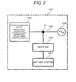
- FIG. 2 is a block diagram schematically showing an electric power system network 101 to which a battery system 201 according to the invention is applied.
- the electric power system network 101 includes an electric power system 102, a power generation device 103, an inverter 104, and a battery system 201 according to the invention, as shown in FIG. 2 .
- the power generation device 103 has a function of supplying, for example, electric power generated from renewable energy to the electric power system 102.
- the battery system 201 is connected via the inverter 104.
- the inverter 104 has a function of converting electric power generated by the power generation device 103 to DC power and supplying the converted DC power to the battery system 201, and a function of converting DC power stored in the battery system 201 to AC power and supplying the converted AC power to the electric power system 102. Power delivery to a load is carried out via the AC power electric system 102.
- the output thereof fluctuates due to the influence of changes in the natural environment such as weather and seasons. This output fluctuation causes frequency fluctuation and voltage fluctuation in the electric power system 102 and therefore is a factor in the lowering of the power quality of the electric power system 102.
- the battery system 201 functions so that the frequency and voltage fluctuation in the electric power system 102 falls within a predetermined range. That is, the battery system 201 has a so-called buffer function such that when excess power is supplied to the electric power system 102, the battery system 201 is charged with the excess power, whereas when power is insufficient, the power stored in the battery system 201 is discharged.
- the battery system 201 according to the invention can restrain frequency fluctuation and voltage fluctuation in the electric power system 102.
- FIG. 3 is a block diagram conceptually showing hierarchical structures of the battery system 201 according to the invention.
- the battery system 201 according to the invention includes a battery module 30 as a minimum unit, a battery pack 40 including plural battery modules 30, and a battery block 50 including plural battery packs 40.
- the battery module 30 has a battery cell group 20, a cell control unit (CCU) 210 which collects battery information of the battery cell group 20 (for example, current information, voltage information, temperature information, state of charge and the like of battery cells), and a battery module control unit (BMCU) 31.
- the cell control unit 210 also performs balancing control between battery cells, which will be described later.
- the battery information collected by the cell control unit 210 is sent to the battery module control unit (BMCU) 31.
- the battery module control unit (BMCU) 31 calculates an average state of charge of the battery cell group 20 in the battery module 30, adds the battery information of the average state of charge of the battery cell group 20 to the above battery information, and transmits the battery information to a battery pack control unit (BPCU) 230, which is on a higher level.
- BMCU battery module control unit
- the battery pack 40 has plural battery modules 30 and a battery pack control unit 230.
- the battery pack control unit 230 collects battery information outputted from each battery module control unit 31 and calculates information of an average state of charge of the battery modules 30, which is the average of the states of charge of the battery modules 30 in the battery pack 40.
- the information of the average state of charge of the plural battery modules 30 is added to the battery information acquired from the battery module control unit 31, and the battery information is outputted to a battery block control unit 240, which is on a still higher level.
- the battery block 50 has plural battery packs 40 and a battery block control unit 240.
- the battery block control unit 240 collects battery information outputted from each battery pack control unit 230 and calculates information of an average state of charge of the battery packs 40, which is the average of the states of charge of the battery packs 40 in the battery block 50.
- the information of the average state of charge of the plural battery packs 40 is added to the battery information acquired from the battery pack control unit 230, and the battery information is outputted to a system control unit 250, which is on a still higher level.
- the battery system 201 since the states of batteries are thus monitored in plural hierarchical levels, the battery system 201 has a high level of safety. Also, since each of the battery module 30, the battery pack 40 and the battery block 50 according to the invention can be replaced on the respective levels, the battery system is easy to maintain.
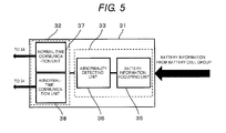
- the battery module control unit 31 has an information processing unit 33 which acquires battery information (for example, current information, voltage information, temperature information) of the battery cell group 20, and a communication unit 32 which transmits the battery information acquired by the information processing unit 33 to the battery pack control unit 230 and receives a control signal from the battery pack control unit 230.
- the battery cell group 20 may include plural battery cells ("c1" to "ck", where k is the number of battery cells) as shown in FIG. 4 or may be formed by a single battery cell.
- the communication unit 32 is a device capable of communication at frequencies f(1) to f(n) converted to a communication frequency corresponding to the battery pack control unit 230 as a main unit, as will be described later.
- the battery pack control unit 230 has a communication unit 42 which receives the battery information of the plural battery modules 30 ("1" to "m", where m is the number of battery modules 30) transmitted from the communication unit 32 and transmits the battery information and control signal to the battery module control unit 31 and the battery block control unit 240, and an arithmetic unit 41 which determines whether balancing between battery modules is necessary or not based on the battery information of each battery module 30 received by the communication unit 42 and calculates the state of charge (SOC) of the battery module 30.
- SOC state of charge
- the communication unit 42 is a device capable of receiving a signal with one of the frequencies f(1) to f(n) outputted and modulated from the battery module as a sub unit and communicating a control signal converted from the above frequency to a communication frequency f(0) corresponding to the battery block control unit 240 as a main unit. Also, the communication unit 42 of the battery pack control unit 230 is configured not to take in other communication frequencies than the communication frequency of the own unit (for example, if it is a battery pack control unit (1), the corresponding communication frequency f(1)) and the communication frequency f(0) used for communication with the battery block control unit 240 as the main unit.
- the battery block control unit 240 has a communication unit 52 which receives the battery information outputted from the plural battery pack control units 230 ("1" to "n", where n is the number of battery packs 40) transmitted from the communication unit 32 and transmits the battery information and control signal to a control unit on a still higher level, not shown, and the battery pack control unit 230.
- the battery block control unit 240 also has an arithmetic unit 51 which determines whether balancing between battery packs is necessary or not based on the battery information of each battery pack 40 received by the communication unit 52 and calculates the state of charge (SOC) of the battery pack 40.
- SOC state of charge
- the communication unit 52 is configured to be capable of receiving and transmitting the control signal with the communication frequency f(0) outputted and modulated from the battery pack control unit 230 as a sub unit.
- the communication frequencies f(0) and f(1) to f(n) are, for example, in a range of 100 MHz to 10 GHz, wireless communication as well as wired communication can be used.
- the communication unit 32 of each battery module 30 is connected to the battery pack control unit 230 on a higher level via a communication line 34.
- Each battery pack control unit 230 is connected to each battery block control unit 240 via a communication line 44 and successive communication is carried out with a higher-level control unit as a main unit.
- the communication method will be described in detail later.
- the communication line may be wired or wireless. Wired communication is advantageous in that the rate of signal transmission error is low, whereas wireless communication is advantageous in that there is no need to arrange wiring.
- frequency modulation which is not easily influenced by other signals, is used as a modulation technique.
- other modulation techniques may also be used.
- the battery module control unit 31 has the communication unit 32 and the information processing unit 33.
- the information processing unit 33 has a battery information acquiring unit 35 and an abnormality detecting unit 36 which detects whether there is an abnormality occurring in the battery module, based on the battery information acquired by the battery information acquiring unit 35.
- the abnormality detecting unit 36 determines whether the acquired battery information falls within a predetermined current range, falls within a predetermined voltage range and falls within a predetermined temperature range.
- a modulated signal f(1) to f(n) is outputted to the battery pack control unit 230 from a normal-time communication unit 37 in the communication unit 32. A specific determination flow will be described later with reference to FIGS. 7A to 7C .
- a control signal with the frequency f(1) to f(n), which is the communication frequency of the battery pack control unit 230 as the main unit, and a control signal with the frequency f(0), which is the communication frequency of the battery block control unit 240 as the main unit further above the main unit of the battery module, are outputted from an abnormal-time communication unit 38.
- the communication unit 42 of the battery pack control unit 230 is configured not to take in other signals than controls signals with the communication frequency of the own unit (for example, if it is the battery pack control unit (1), the corresponding communication frequency f(1)) and the frequency f(0), which is the communication frequency of the main unit. Therefore, abnormality information of the battery module 30 is inputted directly to the communication unit 52 of the battery block control unit 240.
- the battery block control unit 240 can double-check any abnormality using the signal with the frequency f(0) outputted from the battery module control unit 31 and the signal calculated and modulated to the frequency f(0) by the battery pack control unit 230. Thus, reliability is improved.
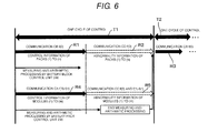
- Communication CA and communication CB indicated by solid lines represent the frequency of a control signal at normal time when there is no abnormality.
- communication CC and communication CD indicated by dotted lines represent the frequency of a control signal at the time of occurrence of abnormality.
- the communication unit 52 of the battery block control unit 240 can receive a control signal with the communication frequency f(1) to f(n) of each battery pack control unit as a sub unit of the battery block.
- the cycle of communication between the battery block control unit 240 and the battery pack control unit 230 is the sum of a time R1 of the communication CB, which is normal control information, and a time R2 of the communication CD corresponding to the case where an abnormality occurs in the battery pack 40, and the length of the control cycle is T1.
- the time R2 of the communication CD section is a blank.
- the cycle of communication between the battery pack control unit 230 and the battery module control unit 31 is the sum of a time R4, which is normal control information, and a time R5 of the communication CC corresponding to the case where an abnormality occurs in the battery module 30, and the sum of the times R4 and R5 is the same as the length T1 of the control cycle.
- the time R5 of the communication CC section is a blank, as in the above communication between the battery pack control unit 230 and the battery block control unit 240.
- the time R1 of the communication CB and the time R4 of the communication CA are the same length.
- the time R2 of the communication CD and the time R5 of the communication CC are the same length.
- the start times of the communication CB and the communication CA are synchronized.
- the battery pack control unit 230 is adopted as an own unit, the communication cycle between the own unit and the main unit and the control cycle between the own unit and the sub unit are the same cycle and synchronized.
- the signal with the frequency f(0) inputted to the battery block control unit 240 can interrupt the communication CD section and communication delay generated by the signal interruption due to a shift in the communication cycle can be restrained.
- the arithmetic unit 41 of the battery pack control unit 230 starts measuring and arithmetic processing of the battery information. After that, when the measuring and arithmetic processing is finished, in the cycle following the end of the processing, the information measured and arithmetically processed by the battery pack control unit 230 is modulated to the frequency f(0) and outputted to the battery block control unit 240. In FIG. 6 , since the measuring and arithmetic processing is finished within a control cycle 1S, the control signal is outputted in the next cycle T2 as the communication CB of the cycle T2.
- Similar control is carried out when the communication CB (that is, a control signal with the frequency f(0)) is inputted to the battery block control unit 240.
- the communication CB that is, a control signal with the frequency f(0)
- arithmetic processing ends and the calculated information is stored in a memory, not shown, provided in the battery block control unit 240.
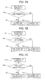
- step S1 battery information (here, voltage information) acquired by the battery information acquiring unit 35 is inputted to the abnormality detecting unit 36.
- step S2 whether the acquired voltage of the battery cell is within a predetermined voltage range (here, for example, within a range of 2.7 to 4.2 V) is determined. If the voltage is determined here as within the predetermined range, the processing goes to step S3.
- a predetermined voltage range here, for example, within a range of 2.7 to 4.2 V
- the abnormality detecting unit 36 selects communication via the normal-time communication unit 37 and a control signal with the frequency f(1) to f(n) corresponding to the battery pack control unit 230 as the main unit of the battery module control unit 31 is outputted from this battery module control unit 31. Meanwhile, if the voltage is determined as not within the predetermined range in step S2, the processing goes to step S4. Communication via the abnormal-time communication unit 38 is selected and a control signal with one of the above frequencies f(1) to f(n) and a signal with the frequency f(0) corresponding to the communication of the battery block control unit 240 are outputted. The processing is thus carried out by the battery module control unit 31.
- step S11 the current information of the current flowing through the battery cell is inputted.
- step S21 whether the current value is above a predetermined range, that is, overcurrent (here, for example, whether the current of 10A or higher is flowing) is determined. If the current has the predetermined current value or below, the processing goes to step S3. If the current has the predetermined current value or above, the processing goes to step S4. Then, similar processing to steps S3 and S4 of FIG. 7A is carried out.
- step S12 the temperature information of the battery cell is inputted.
- step S22 whether the temperature information is within a predetermined range is determined.
- the temperature range is decided by setting a temperature condition to be used. For example, in this embodiment, the temperature is set within a range of 0 to 30°C. If the battery temperature is within the predetermined range, the processing goes to step S3. If the battery temperature is outside the predetermined range, the processing goes to step S4. Then, similar processing to steps S3 and S4 of FIG. 7A is carried out.
- the abnormality detecting unit 36 Since such control is performed in the abnormality detecting unit 36, when an abnormality occurs in the battery module 30, the abnormality can securely be detected and communication delay can be restrained, thus controlling the battery system.
- a battery system in which delay in communication and processing is restrained even if the battery system is constructed with plural hierarchical structures can be provided.
Landscapes
- Engineering & Computer Science (AREA)
- Manufacturing & Machinery (AREA)
- Chemical & Material Sciences (AREA)
- Chemical Kinetics & Catalysis (AREA)
- Electrochemistry (AREA)
- General Chemical & Material Sciences (AREA)
- Computer Networks & Wireless Communication (AREA)
- Charge And Discharge Circuits For Batteries Or The Like (AREA)
- Remote Monitoring And Control Of Power-Distribution Networks (AREA)
Applications Claiming Priority (1)
| Application Number | Priority Date | Filing Date | Title |
|---|---|---|---|
| JP2012075393A JP5872354B2 (ja) | 2012-03-29 | 2012-03-29 | 電池システム |
Publications (3)
| Publication Number | Publication Date |
|---|---|
| EP2645734A2 true EP2645734A2 (de) | 2013-10-02 |
| EP2645734A3 EP2645734A3 (de) | 2017-10-18 |
| EP2645734B1 EP2645734B1 (de) | 2019-08-28 |
Family
ID=47739147
Family Applications (1)
| Application Number | Title | Priority Date | Filing Date |
|---|---|---|---|
| EP13156070.8A Active EP2645734B1 (de) | 2012-03-29 | 2013-02-21 | Batteriesystem |
Country Status (4)
| Country | Link |
|---|---|
| US (1) | US20130260198A1 (de) |
| EP (1) | EP2645734B1 (de) |
| JP (1) | JP5872354B2 (de) |
| CN (1) | CN103367819B (de) |
Families Citing this family (10)
| Publication number | Priority date | Publication date | Assignee | Title |
|---|---|---|---|---|
| WO2015121979A1 (ja) | 2014-02-14 | 2015-08-20 | 株式会社日立製作所 | 電池制御システム、電池システム |
| US10256513B2 (en) * | 2014-05-26 | 2019-04-09 | Hitachi, Ltd. | Battery system |
| US10644510B2 (en) * | 2015-08-14 | 2020-05-05 | Solarcity Corporation | Multiple energy storage devices for inverter power control systems in an energy generation system |
| TWI568122B (zh) * | 2015-11-09 | 2017-01-21 | 財團法人工業技術研究院 | 電池系統與其控制方法 |
| US11309714B2 (en) | 2016-11-02 | 2022-04-19 | Tesla, Inc. | Micro-batteries for energy generation systems |
| CN108400608A (zh) * | 2018-05-24 | 2018-08-14 | 华升智联科技(深圳)有限公司 | 一种电力储能柜智慧环境系统 |
| CN110896158B (zh) * | 2018-09-12 | 2020-11-10 | 宁德时代新能源科技股份有限公司 | 电池管理系统、电池管理单元和待管理单元 |
| JP7226244B2 (ja) * | 2019-10-29 | 2023-02-21 | 株式会社デンソー | 通信システム |
| DE102020209682A1 (de) | 2020-07-31 | 2022-02-03 | Robert Bosch Gesellschaft mit beschränkter Haftung | Verfahren zum Betreiben einer Vorrichtung und Vorrichtung |
| KR102819854B1 (ko) * | 2022-05-27 | 2025-06-12 | 주식회사 엘지에너지솔루션 | 배터리 공유 장치 |
Citations (1)
| Publication number | Priority date | Publication date | Assignee | Title |
|---|---|---|---|---|
| JP2009538112A (ja) | 2006-05-15 | 2009-10-29 | エイ 123 システムズ,インク. | マルチプルフォールトトレランスを有しマルチ構成可能なスケーラブル冗長バッテリモジュール |
Family Cites Families (8)
| Publication number | Priority date | Publication date | Assignee | Title |
|---|---|---|---|---|
| JP4343173B2 (ja) * | 2002-11-25 | 2009-10-14 | ティアックス エルエルシー | 直列接続された電気エネルギー貯蔵ユニット間の充電状態を均等化するバッテリーセル平衡化システム |
| JP2008283589A (ja) * | 2007-05-14 | 2008-11-20 | Oki Electric Ind Co Ltd | 通信データ中継方法、通信データ中継プログラム |
| WO2009020158A1 (ja) * | 2007-08-06 | 2009-02-12 | Panasonic Electric Works Co., Ltd. | 機器管理システム |
| JP2010029015A (ja) * | 2008-07-23 | 2010-02-04 | Mitsubishi Heavy Ind Ltd | 組電池システム |
| JP2010029050A (ja) * | 2008-07-24 | 2010-02-04 | Toshiba Corp | 電池システム |
| US8417472B2 (en) * | 2008-12-19 | 2013-04-09 | 02Micro Inc. | Synchronized data sampling systems and methods |
| CN101895132B (zh) * | 2009-05-20 | 2012-07-04 | 常德毅力能源有限公司 | 一种电动摩托车电池管理系统 |
| JP5562617B2 (ja) * | 2009-11-30 | 2014-07-30 | 三洋電機株式会社 | 均等化装置、バッテリシステムおよび電動車両 |
-
2012
- 2012-03-29 JP JP2012075393A patent/JP5872354B2/ja not_active Expired - Fee Related
-
2013
- 2013-02-15 US US13/768,070 patent/US20130260198A1/en not_active Abandoned
- 2013-02-20 CN CN201310054276.3A patent/CN103367819B/zh not_active Expired - Fee Related
- 2013-02-21 EP EP13156070.8A patent/EP2645734B1/de active Active
Patent Citations (1)
| Publication number | Priority date | Publication date | Assignee | Title |
|---|---|---|---|---|
| JP2009538112A (ja) | 2006-05-15 | 2009-10-29 | エイ 123 システムズ,インク. | マルチプルフォールトトレランスを有しマルチ構成可能なスケーラブル冗長バッテリモジュール |
Also Published As
| Publication number | Publication date |
|---|---|
| EP2645734A3 (de) | 2017-10-18 |
| JP2013207945A (ja) | 2013-10-07 |
| CN103367819A (zh) | 2013-10-23 |
| CN103367819B (zh) | 2016-01-06 |
| EP2645734B1 (de) | 2019-08-28 |
| US20130260198A1 (en) | 2013-10-03 |
| JP5872354B2 (ja) | 2016-03-01 |
Similar Documents
| Publication | Publication Date | Title |
|---|---|---|
| EP2645734B1 (de) | Batteriesystem | |
| US10256513B2 (en) | Battery system | |
| US9013152B2 (en) | Power stabilization system and power stabilizing method | |
| EP3183791B1 (de) | Elektrisches speichersystem | |
| US20130257440A1 (en) | Relay Welding Detector of Battery System and Battery System Which Uses the Detector | |
| EP2549581B1 (de) | Batterievorrichtung zur Steuerung mehrerer Batterien und Steuerverfahren für mehrere Batterien | |
| JP6003048B2 (ja) | 発電装置 | |
| US9885758B2 (en) | Voltage monitoring device for assembled battery | |
| EP2645448A1 (de) | Batteriepack und Batteriesystem | |
| EP2658027A1 (de) | Stromversorgungssystem | |
| US20200398696A1 (en) | Battery management system with operating envelope output for an external controller | |
| US10418826B2 (en) | Battery device and charging device | |
| JP2007174894A (ja) | 電池管理システム、電池管理方法、電池システム及び自動車 | |
| CN103311980A (zh) | 电池电压监视电路 | |
| CN119318090A (zh) | 用于能量存储系统的通信系统和同步技术 | |
| JP2011106855A (ja) | 電源装置 | |
| KR20250166979A (ko) | 배터리 관리 시스템, 배터리, 차량, 및 배터리 관리 방법 | |
| JP2014211402A (ja) | 複合セル状態監視装置、複合セル状態監視システムおよび複合セル状態監視方法 | |
| US20240250393A1 (en) | Pcba configuration for voltage/temperature sensing | |
| JP5205654B2 (ja) | 分散直流電源制御回路 | |
| JP6049603B2 (ja) | 電池制御システム及び電池制御方法 | |
| US11056724B2 (en) | Power storage system | |
| JP7606492B2 (ja) | 蓄電池制御装置、及び蓄電池接続制御装置 | |
| CN103358926A (zh) | 电池监视系统以及半导体装置 | |
| US20240014672A1 (en) | Power supply device |
Legal Events
| Date | Code | Title | Description |
|---|---|---|---|
| PUAI | Public reference made under article 153(3) epc to a published international application that has entered the european phase |
Free format text: ORIGINAL CODE: 0009012 |
|
| 17P | Request for examination filed |
Effective date: 20130412 |
|
| AK | Designated contracting states |
Kind code of ref document: A2 Designated state(s): AL AT BE BG CH CY CZ DE DK EE ES FI FR GB GR HR HU IE IS IT LI LT LU LV MC MK MT NL NO PL PT RO RS SE SI SK SM TR |
|
| AX | Request for extension of the european patent |
Extension state: BA ME |
|
| PUAL | Search report despatched |
Free format text: ORIGINAL CODE: 0009013 |
|
| AK | Designated contracting states |
Kind code of ref document: A3 Designated state(s): AL AT BE BG CH CY CZ DE DK EE ES FI FR GB GR HR HU IE IS IT LI LT LU LV MC MK MT NL NO PL PT RO RS SE SI SK SM TR |
|
| AX | Request for extension of the european patent |
Extension state: BA ME |
|
| RIC1 | Information provided on ipc code assigned before grant |
Ipc: H01M 10/00 20060101ALI20170911BHEP Ipc: H04Q 9/00 20060101AFI20170911BHEP |
|
| GRAP | Despatch of communication of intention to grant a patent |
Free format text: ORIGINAL CODE: EPIDOSNIGR1 |
|
| STAA | Information on the status of an ep patent application or granted ep patent |
Free format text: STATUS: GRANT OF PATENT IS INTENDED |
|
| RIC1 | Information provided on ipc code assigned before grant |
Ipc: H01M 10/00 20060101ALI20190227BHEP Ipc: H04Q 9/00 20060101AFI20190227BHEP |
|
| INTG | Intention to grant announced |
Effective date: 20190326 |
|
| GRAS | Grant fee paid |
Free format text: ORIGINAL CODE: EPIDOSNIGR3 |
|
| GRAA | (expected) grant |
Free format text: ORIGINAL CODE: 0009210 |
|
| STAA | Information on the status of an ep patent application or granted ep patent |
Free format text: STATUS: THE PATENT HAS BEEN GRANTED |
|
| AK | Designated contracting states |
Kind code of ref document: B1 Designated state(s): AL AT BE BG CH CY CZ DE DK EE ES FI FR GB GR HR HU IE IS IT LI LT LU LV MC MK MT NL NO PL PT RO RS SE SI SK SM TR |
|
| REG | Reference to a national code |
Ref country code: GB Ref legal event code: FG4D |
|
| REG | Reference to a national code |
Ref country code: CH Ref legal event code: EP |
|
| REG | Reference to a national code |
Ref country code: AT Ref legal event code: REF Ref document number: 1173913 Country of ref document: AT Kind code of ref document: T Effective date: 20190915 |
|
| REG | Reference to a national code |
Ref country code: IE Ref legal event code: FG4D |
|
| REG | Reference to a national code |
Ref country code: DE Ref legal event code: R096 Ref document number: 602013059646 Country of ref document: DE |
|
| REG | Reference to a national code |
Ref country code: NL Ref legal event code: MP Effective date: 20190828 |
|
| REG | Reference to a national code |
Ref country code: LT Ref legal event code: MG4D |
|
| PG25 | Lapsed in a contracting state [announced via postgrant information from national office to epo] |
Ref country code: NL Free format text: LAPSE BECAUSE OF FAILURE TO SUBMIT A TRANSLATION OF THE DESCRIPTION OR TO PAY THE FEE WITHIN THE PRESCRIBED TIME-LIMIT Effective date: 20190828 Ref country code: BG Free format text: LAPSE BECAUSE OF FAILURE TO SUBMIT A TRANSLATION OF THE DESCRIPTION OR TO PAY THE FEE WITHIN THE PRESCRIBED TIME-LIMIT Effective date: 20191128 Ref country code: SE Free format text: LAPSE BECAUSE OF FAILURE TO SUBMIT A TRANSLATION OF THE DESCRIPTION OR TO PAY THE FEE WITHIN THE PRESCRIBED TIME-LIMIT Effective date: 20190828 Ref country code: NO Free format text: LAPSE BECAUSE OF FAILURE TO SUBMIT A TRANSLATION OF THE DESCRIPTION OR TO PAY THE FEE WITHIN THE PRESCRIBED TIME-LIMIT Effective date: 20191128 Ref country code: HR Free format text: LAPSE BECAUSE OF FAILURE TO SUBMIT A TRANSLATION OF THE DESCRIPTION OR TO PAY THE FEE WITHIN THE PRESCRIBED TIME-LIMIT Effective date: 20190828 Ref country code: PT Free format text: LAPSE BECAUSE OF FAILURE TO SUBMIT A TRANSLATION OF THE DESCRIPTION OR TO PAY THE FEE WITHIN THE PRESCRIBED TIME-LIMIT Effective date: 20191230 Ref country code: FI Free format text: LAPSE BECAUSE OF FAILURE TO SUBMIT A TRANSLATION OF THE DESCRIPTION OR TO PAY THE FEE WITHIN THE PRESCRIBED TIME-LIMIT Effective date: 20190828 Ref country code: LT Free format text: LAPSE BECAUSE OF FAILURE TO SUBMIT A TRANSLATION OF THE DESCRIPTION OR TO PAY THE FEE WITHIN THE PRESCRIBED TIME-LIMIT Effective date: 20190828 |
|
| PG25 | Lapsed in a contracting state [announced via postgrant information from national office to epo] |
Ref country code: LV Free format text: LAPSE BECAUSE OF FAILURE TO SUBMIT A TRANSLATION OF THE DESCRIPTION OR TO PAY THE FEE WITHIN THE PRESCRIBED TIME-LIMIT Effective date: 20190828 Ref country code: RS Free format text: LAPSE BECAUSE OF FAILURE TO SUBMIT A TRANSLATION OF THE DESCRIPTION OR TO PAY THE FEE WITHIN THE PRESCRIBED TIME-LIMIT Effective date: 20190828 Ref country code: ES Free format text: LAPSE BECAUSE OF FAILURE TO SUBMIT A TRANSLATION OF THE DESCRIPTION OR TO PAY THE FEE WITHIN THE PRESCRIBED TIME-LIMIT Effective date: 20190828 Ref country code: IS Free format text: LAPSE BECAUSE OF FAILURE TO SUBMIT A TRANSLATION OF THE DESCRIPTION OR TO PAY THE FEE WITHIN THE PRESCRIBED TIME-LIMIT Effective date: 20191228 Ref country code: GR Free format text: LAPSE BECAUSE OF FAILURE TO SUBMIT A TRANSLATION OF THE DESCRIPTION OR TO PAY THE FEE WITHIN THE PRESCRIBED TIME-LIMIT Effective date: 20191129 Ref country code: AL Free format text: LAPSE BECAUSE OF FAILURE TO SUBMIT A TRANSLATION OF THE DESCRIPTION OR TO PAY THE FEE WITHIN THE PRESCRIBED TIME-LIMIT Effective date: 20190828 |
|
| REG | Reference to a national code |
Ref country code: AT Ref legal event code: MK05 Ref document number: 1173913 Country of ref document: AT Kind code of ref document: T Effective date: 20190828 |
|
| PG25 | Lapsed in a contracting state [announced via postgrant information from national office to epo] |
Ref country code: TR Free format text: LAPSE BECAUSE OF FAILURE TO SUBMIT A TRANSLATION OF THE DESCRIPTION OR TO PAY THE FEE WITHIN THE PRESCRIBED TIME-LIMIT Effective date: 20190828 |
|
| PG25 | Lapsed in a contracting state [announced via postgrant information from national office to epo] |
Ref country code: PL Free format text: LAPSE BECAUSE OF FAILURE TO SUBMIT A TRANSLATION OF THE DESCRIPTION OR TO PAY THE FEE WITHIN THE PRESCRIBED TIME-LIMIT Effective date: 20190828 Ref country code: RO Free format text: LAPSE BECAUSE OF FAILURE TO SUBMIT A TRANSLATION OF THE DESCRIPTION OR TO PAY THE FEE WITHIN THE PRESCRIBED TIME-LIMIT Effective date: 20190828 Ref country code: DK Free format text: LAPSE BECAUSE OF FAILURE TO SUBMIT A TRANSLATION OF THE DESCRIPTION OR TO PAY THE FEE WITHIN THE PRESCRIBED TIME-LIMIT Effective date: 20190828 Ref country code: IT Free format text: LAPSE BECAUSE OF FAILURE TO SUBMIT A TRANSLATION OF THE DESCRIPTION OR TO PAY THE FEE WITHIN THE PRESCRIBED TIME-LIMIT Effective date: 20190828 Ref country code: AT Free format text: LAPSE BECAUSE OF FAILURE TO SUBMIT A TRANSLATION OF THE DESCRIPTION OR TO PAY THE FEE WITHIN THE PRESCRIBED TIME-LIMIT Effective date: 20190828 Ref country code: EE Free format text: LAPSE BECAUSE OF FAILURE TO SUBMIT A TRANSLATION OF THE DESCRIPTION OR TO PAY THE FEE WITHIN THE PRESCRIBED TIME-LIMIT Effective date: 20190828 |
|
| PG25 | Lapsed in a contracting state [announced via postgrant information from national office to epo] |
Ref country code: IS Free format text: LAPSE BECAUSE OF FAILURE TO SUBMIT A TRANSLATION OF THE DESCRIPTION OR TO PAY THE FEE WITHIN THE PRESCRIBED TIME-LIMIT Effective date: 20200224 Ref country code: SM Free format text: LAPSE BECAUSE OF FAILURE TO SUBMIT A TRANSLATION OF THE DESCRIPTION OR TO PAY THE FEE WITHIN THE PRESCRIBED TIME-LIMIT Effective date: 20190828 Ref country code: CZ Free format text: LAPSE BECAUSE OF FAILURE TO SUBMIT A TRANSLATION OF THE DESCRIPTION OR TO PAY THE FEE WITHIN THE PRESCRIBED TIME-LIMIT Effective date: 20190828 Ref country code: SK Free format text: LAPSE BECAUSE OF FAILURE TO SUBMIT A TRANSLATION OF THE DESCRIPTION OR TO PAY THE FEE WITHIN THE PRESCRIBED TIME-LIMIT Effective date: 20190828 |
|
| REG | Reference to a national code |
Ref country code: DE Ref legal event code: R097 Ref document number: 602013059646 Country of ref document: DE |
|
| PLBE | No opposition filed within time limit |
Free format text: ORIGINAL CODE: 0009261 |
|
| STAA | Information on the status of an ep patent application or granted ep patent |
Free format text: STATUS: NO OPPOSITION FILED WITHIN TIME LIMIT |
|
| PG2D | Information on lapse in contracting state deleted |
Ref country code: IS |
|
| 26N | No opposition filed |
Effective date: 20200603 |
|
| PG25 | Lapsed in a contracting state [announced via postgrant information from national office to epo] |
Ref country code: SI Free format text: LAPSE BECAUSE OF FAILURE TO SUBMIT A TRANSLATION OF THE DESCRIPTION OR TO PAY THE FEE WITHIN THE PRESCRIBED TIME-LIMIT Effective date: 20190828 |
|
| REG | Reference to a national code |
Ref country code: CH Ref legal event code: PL |
|
| GBPC | Gb: european patent ceased through non-payment of renewal fee |
Effective date: 20200221 |
|
| REG | Reference to a national code |
Ref country code: BE Ref legal event code: MM Effective date: 20200229 |
|
| PG25 | Lapsed in a contracting state [announced via postgrant information from national office to epo] |
Ref country code: LU Free format text: LAPSE BECAUSE OF NON-PAYMENT OF DUE FEES Effective date: 20200221 Ref country code: MC Free format text: LAPSE BECAUSE OF FAILURE TO SUBMIT A TRANSLATION OF THE DESCRIPTION OR TO PAY THE FEE WITHIN THE PRESCRIBED TIME-LIMIT Effective date: 20190828 |
|
| PG25 | Lapsed in a contracting state [announced via postgrant information from national office to epo] |
Ref country code: LI Free format text: LAPSE BECAUSE OF NON-PAYMENT OF DUE FEES Effective date: 20200229 Ref country code: CH Free format text: LAPSE BECAUSE OF NON-PAYMENT OF DUE FEES Effective date: 20200229 |
|
| PG25 | Lapsed in a contracting state [announced via postgrant information from national office to epo] |
Ref country code: GB Free format text: LAPSE BECAUSE OF NON-PAYMENT OF DUE FEES Effective date: 20200221 Ref country code: FR Free format text: LAPSE BECAUSE OF NON-PAYMENT OF DUE FEES Effective date: 20200229 Ref country code: IE Free format text: LAPSE BECAUSE OF NON-PAYMENT OF DUE FEES Effective date: 20200221 |
|
| PG25 | Lapsed in a contracting state [announced via postgrant information from national office to epo] |
Ref country code: BE Free format text: LAPSE BECAUSE OF NON-PAYMENT OF DUE FEES Effective date: 20200229 |
|
| PG25 | Lapsed in a contracting state [announced via postgrant information from national office to epo] |
Ref country code: MT Free format text: LAPSE BECAUSE OF FAILURE TO SUBMIT A TRANSLATION OF THE DESCRIPTION OR TO PAY THE FEE WITHIN THE PRESCRIBED TIME-LIMIT Effective date: 20190828 Ref country code: CY Free format text: LAPSE BECAUSE OF FAILURE TO SUBMIT A TRANSLATION OF THE DESCRIPTION OR TO PAY THE FEE WITHIN THE PRESCRIBED TIME-LIMIT Effective date: 20190828 |
|
| PG25 | Lapsed in a contracting state [announced via postgrant information from national office to epo] |
Ref country code: MK Free format text: LAPSE BECAUSE OF FAILURE TO SUBMIT A TRANSLATION OF THE DESCRIPTION OR TO PAY THE FEE WITHIN THE PRESCRIBED TIME-LIMIT Effective date: 20190828 |
|
| PGFP | Annual fee paid to national office [announced via postgrant information from national office to epo] |
Ref country code: DE Payment date: 20241231 Year of fee payment: 13 |