EP2646740B1 - Projecteur à led comportant un réflecteur - Google Patents
Projecteur à led comportant un réflecteur Download PDFInfo
- Publication number
- EP2646740B1 EP2646740B1 EP11815431.9A EP11815431A EP2646740B1 EP 2646740 B1 EP2646740 B1 EP 2646740B1 EP 11815431 A EP11815431 A EP 11815431A EP 2646740 B1 EP2646740 B1 EP 2646740B1
- Authority
- EP
- European Patent Office
- Prior art keywords
- led
- scattering
- reflector
- cap
- spotlight according
- Prior art date
- Legal status (The legal status is an assumption and is not a legal conclusion. Google has not performed a legal analysis and makes no representation as to the accuracy of the status listed.)
- Active
Links
- 239000002245 particle Substances 0.000 claims description 24
- 239000000463 material Substances 0.000 claims description 13
- 238000006243 chemical reaction Methods 0.000 claims description 12
- 238000000034 method Methods 0.000 claims description 10
- 238000001816 cooling Methods 0.000 claims description 5
- 238000002347 injection Methods 0.000 claims description 2
- 239000007924 injection Substances 0.000 claims description 2
- 238000009434 installation Methods 0.000 claims description 2
- 239000011248 coating agent Substances 0.000 claims 2
- 238000000576 coating method Methods 0.000 claims 2
- 229920002994 synthetic fiber Polymers 0.000 claims 1
- 239000011159 matrix material Substances 0.000 description 8
- 229920000642 polymer Polymers 0.000 description 7
- OAICVXFJPJFONN-UHFFFAOYSA-N Phosphorus Chemical compound [P] OAICVXFJPJFONN-UHFFFAOYSA-N 0.000 description 6
- 229920003229 poly(methyl methacrylate) Polymers 0.000 description 5
- 230000005855 radiation Effects 0.000 description 5
- 239000004417 polycarbonate Substances 0.000 description 4
- 229920000515 polycarbonate Polymers 0.000 description 4
- 239000000203 mixture Substances 0.000 description 3
- 239000004033 plastic Substances 0.000 description 3
- 229920003023 plastic Polymers 0.000 description 3
- VYPSYNLAJGMNEJ-UHFFFAOYSA-N Silicium dioxide Chemical compound O=[Si]=O VYPSYNLAJGMNEJ-UHFFFAOYSA-N 0.000 description 2
- GWEVSGVZZGPLCZ-UHFFFAOYSA-N Titan oxide Chemical compound O=[Ti]=O GWEVSGVZZGPLCZ-UHFFFAOYSA-N 0.000 description 2
- 239000003086 colorant Substances 0.000 description 2
- 229920001169 thermoplastic Polymers 0.000 description 2
- 239000004416 thermosoftening plastic Substances 0.000 description 2
- 229910003564 SiAlON Inorganic materials 0.000 description 1
- JRPBQTZRNDNNOP-UHFFFAOYSA-N barium titanate Chemical compound [Ba+2].[Ba+2].[O-][Ti]([O-])([O-])[O-] JRPBQTZRNDNNOP-UHFFFAOYSA-N 0.000 description 1
- 229910002113 barium titanate Inorganic materials 0.000 description 1
- 230000005540 biological transmission Effects 0.000 description 1
- 230000001419 dependent effect Effects 0.000 description 1
- 238000000295 emission spectrum Methods 0.000 description 1
- 239000003822 epoxy resin Substances 0.000 description 1
- 239000011521 glass Substances 0.000 description 1
- 238000005286 illumination Methods 0.000 description 1
- 238000001746 injection moulding Methods 0.000 description 1
- 229910052605 nesosilicate Inorganic materials 0.000 description 1
- 150000004767 nitrides Chemical class 0.000 description 1
- 239000011146 organic particle Substances 0.000 description 1
- 150000004762 orthosilicates Chemical class 0.000 description 1
- 229920000647 polyepoxide Polymers 0.000 description 1
- 235000012239 silicon dioxide Nutrition 0.000 description 1
- 239000000377 silicon dioxide Substances 0.000 description 1
- 229920002050 silicone resin Polymers 0.000 description 1
- 239000000243 solution Substances 0.000 description 1
- 238000001228 spectrum Methods 0.000 description 1
- 239000000126 substance Substances 0.000 description 1
- 239000004408 titanium dioxide Substances 0.000 description 1
- 238000002834 transmittance Methods 0.000 description 1
Images
Classifications
-
- F—MECHANICAL ENGINEERING; LIGHTING; HEATING; WEAPONS; BLASTING
- F21—LIGHTING
- F21K—NON-ELECTRIC LIGHT SOURCES USING LUMINESCENCE; LIGHT SOURCES USING ELECTROCHEMILUMINESCENCE; LIGHT SOURCES USING CHARGES OF COMBUSTIBLE MATERIAL; LIGHT SOURCES USING SEMICONDUCTOR DEVICES AS LIGHT-GENERATING ELEMENTS; LIGHT SOURCES NOT OTHERWISE PROVIDED FOR
- F21K9/00—Light sources using semiconductor devices as light-generating elements, e.g. using light-emitting diodes [LED] or lasers
- F21K9/20—Light sources comprising attachment means
- F21K9/23—Retrofit light sources for lighting devices with a single fitting for each light source, e.g. for substitution of incandescent lamps with bayonet or threaded fittings
- F21K9/233—Retrofit light sources for lighting devices with a single fitting for each light source, e.g. for substitution of incandescent lamps with bayonet or threaded fittings specially adapted for generating a spot light distribution, e.g. for substitution of reflector lamps
-
- F—MECHANICAL ENGINEERING; LIGHTING; HEATING; WEAPONS; BLASTING
- F21—LIGHTING
- F21V—FUNCTIONAL FEATURES OR DETAILS OF LIGHTING DEVICES OR SYSTEMS THEREOF; STRUCTURAL COMBINATIONS OF LIGHTING DEVICES WITH OTHER ARTICLES, NOT OTHERWISE PROVIDED FOR
- F21V13/00—Producing particular characteristics or distribution of the light emitted by means of a combination of elements specified in two or more of main groups F21V1/00 - F21V11/00
- F21V13/02—Combinations of only two kinds of elements
- F21V13/08—Combinations of only two kinds of elements the elements being filters or photoluminescent elements and reflectors
-
- F—MECHANICAL ENGINEERING; LIGHTING; HEATING; WEAPONS; BLASTING
- F21—LIGHTING
- F21V—FUNCTIONAL FEATURES OR DETAILS OF LIGHTING DEVICES OR SYSTEMS THEREOF; STRUCTURAL COMBINATIONS OF LIGHTING DEVICES WITH OTHER ARTICLES, NOT OTHERWISE PROVIDED FOR
- F21V3/00—Globes; Bowls; Cover glasses
- F21V3/04—Globes; Bowls; Cover glasses characterised by materials, surface treatments or coatings
- F21V3/06—Globes; Bowls; Cover glasses characterised by materials, surface treatments or coatings characterised by the material
- F21V3/062—Globes; Bowls; Cover glasses characterised by materials, surface treatments or coatings characterised by the material the material being plastics
-
- F—MECHANICAL ENGINEERING; LIGHTING; HEATING; WEAPONS; BLASTING
- F21—LIGHTING
- F21V—FUNCTIONAL FEATURES OR DETAILS OF LIGHTING DEVICES OR SYSTEMS THEREOF; STRUCTURAL COMBINATIONS OF LIGHTING DEVICES WITH OTHER ARTICLES, NOT OTHERWISE PROVIDED FOR
- F21V3/00—Globes; Bowls; Cover glasses
- F21V3/04—Globes; Bowls; Cover glasses characterised by materials, surface treatments or coatings
- F21V3/10—Globes; Bowls; Cover glasses characterised by materials, surface treatments or coatings characterised by coatings
- F21V3/12—Globes; Bowls; Cover glasses characterised by materials, surface treatments or coatings characterised by coatings the coatings comprising photoluminescent substances
-
- F—MECHANICAL ENGINEERING; LIGHTING; HEATING; WEAPONS; BLASTING
- F21—LIGHTING
- F21Y—INDEXING SCHEME ASSOCIATED WITH SUBCLASSES F21K, F21L, F21S and F21V, RELATING TO THE FORM OR THE KIND OF THE LIGHT SOURCES OR OF THE COLOUR OF THE LIGHT EMITTED
- F21Y2115/00—Light-generating elements of semiconductor light sources
- F21Y2115/10—Light-emitting diodes [LED]
Definitions
- LED radiators in particular for achieving a white light illumination, are well known from the prior art. Under an LED spotlight is to be understood regularly an LED light source having one or more LEDs of the same and different color, the light of the one or more LEDs receives the desired distribution by a reflector.
- a particular problem occurs when LEDs with different emission spectra are used as the light source. It must namely be ensured that before the exit of the mixed light from the various LEDs from the radiator to a sufficient mixing of the light, so that a sufficient color homogeneity of the emitted light over the entire angular range of the emitted light can be achieved.
- the problem of color homogeneity may be exacerbated when the spectrum of at least one of the LEDs of the LED light source is partially converted to a light with other (usually longer wavelength) light by a color conversion layer applied at a distance and / or in contact with the LED Color conversion layer, so to speak represents a third light source, which must be homogeneously mixed with the light emitted by the LEDs.
- a spotlight with an LED light source and a reflector is already known from the WO 02/5047472 , There will be an LED light source arranged on the reflector bottom and a lower portion of the reflector inner volume filled. Also the pamphlets WO 2010/113098 A1 WO 2010/106504 A1 . US 2008/310158 A1 or the DE 10 2007 054206 A1 reveal spotlights with LED light sources and reflectors.
- the spreading cap and the reflector bottom can be on the same level.
- the LED spotlight may have a heat sink in thermal contact with the LED module.
- the scattering cap and the reflector can be designed separately or integrated.
- the translucent medium may comprise phosphor and / or scattering particles.
- the scattering cap can be designed similar to a hollow cylinder, which may have a wall thickness of 1 - 3 mm.
- the spreading cap can be similar to a hollow cylinder, which can have a height of 3 - 10mm and a diameter of 3 - 8mm ..
- the reflector base can have a central opening, through which the LED chips protrude from the base of the LED module, which is arranged below the reflector base, into the stray cap.
- stray cap From the reflector bottom, a preferably integrally formed with this stray cap can wegeroxyn.
- the stray cap and the reflector can be placed on the support of the LED module.
- the LED chips can be covered with a globe-top applied by a dispensing method, for example, or by another cover.
- the LED chips can be monochromatic in the same color or different colors.
- the inner circumferential surface of the reflector may have a parabolic, circular or a straight course or be formed at least partially in the form of facets.
- the inner circumferential surface of the reflector and / or the inner and / or the outer surface of the scattering cap can / can be designed to be reflective, scattering or scattering-reflecting.
- the scattering cap can consist of a plastic filled with scattering particles.
- the inner and / or the outer surface of the scattering cap can / have scattering and / or phosphor particles.
- the inner surface of the scattering cap may contain phosphor particles and the outer surface of the scattering cap may have scattering particles.
- the scattering cap according to the invention has a base on which the reflector is placed and thus the scattering cap is positioned or fixed.
- the leaflet may have a snap-in contact.
- the reflector base and / or the base of the scattering cap can be circular, elliptical or square shaped.
- the reflector may be covered or open by a scatter or color conversion disc.
- LED spotlights can be designed as ceiling spotlights for installation in suspended ceilings.
- LED spotlight can be designed as a retrofit LED reflector lamp and, for example, be equipped with a commercially available version such as. Screw thread, plug-in socket, etc.
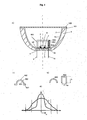
- FIG. 1 shows a cross-sectional view of an LED emitter according to the invention.
- the LED light source is preferably formed by a plurality of LEDs 7, 7 'which are arranged on a carrier 6, thus forming an LED module 5.
- the LED module 5 is in thermal contact with a heat sink 3.
- the LED module 5 and more precisely, the carrier 6 is placed in a central region of the fan-shaped cooling body 3 in the sectional view, or preferably embedded in a central depression of the heat sink bottom.
- the LEDs 7, 7 ' can be monochromatic (UV, blue, red or green) of the same color or different colors.
- a translucent (or at least partially translucent) medium 8 applied by a dispensing method is applied, which may contain color conversion material and / or scattering particles.
- the translucent medium could be prepared by injection or overmolding techniques. Scattering and / or color color version particles may be embedded in the dispensing layer 8 in a polymer matrix (plastic matrix).
- silicone resin epoxy resin or their mixtures can be used.
- color conversion material is to be understood as meaning one or more phosphors used in LEDs (for example garnets (YAG), ortho silicates (BOSE) nitrides (SiAlON)). These phosphors may, for example, green, yellow, yellow / green, red or emit any color. Their mixtures can be formed by two or more of these phosphors of the same and / or different color.
- phosphors used in LEDs for example garnets (YAG), ortho silicates (BOSE) nitrides (SiAlON)
- YAG garnets
- BOSE ortho silicates
- SiAlON ortho silicates
- These phosphors may, for example, green, yellow, yellow / green, red or emit any color. Their mixtures can be formed by two or more of these phosphors of the same and / or different color.
- scattering particles one can apply inorganic (eg silicon dioxide, titanium dioxide, barium titanate, small glass ball) and / or organic particles (eg organic scattering particles can be produced from the polymer matrix itself).
- inorganic eg silicon dioxide, titanium dioxide, barium titanate, small glass ball
- organic particles eg organic scattering particles can be produced from the polymer matrix itself.
- the refractive index difference between scattering particle and polymer matrix can be between +/- 0.0003 and +/- 3. It is preferably between +/- 0.05 and +/- 1.5.
- the LED module 5 is arranged as shown so that it is inserted from the outside through a central opening in the bottom 60 of a reflector 2, such that at least a portion of the LEDs 7, 7 'but preferably the entire side surface of the LEDs 7, 7 'a the interior of the reflector 2 protrudes.
- the LEDs 7, 7 ' are surrounded by a stray cap 900.
- the stray cap 900 and the reflector 2 are placed on the support 6 of the LED module 5.
- the bottoms of the scattering cap and the reflector lie according to the illustrated embodiment on a plane, so are aligned in the side view.
- the scattering cap can be offset to the rear. In this case, therefore, the bottom of the leaflet with respect.
- the reflector base is offset to the rear.
- the LEDs can all lie behind the plane formed by the reflector bottom.
- the outlet side of the mixing chamber located in the light emission direction can lie on the level of the reflector base, or can project slightly into the interior of the reflector.
- the lobe walls 904 may be laterally spaced from, or in contact with, the dispensing layer 8.
- the scattering cap 900 is partially unfilled, thus containing an air layer between the LEDs 7, 7 'or the optional dispensing layer 8 and the exit plane (defined by the edge of the spreading cap 900).
- this cover 900 is thus an example of color conversion material in the light emission direction but spaced from the LEDs 7, 7 '. can be arranged. Between this color conversion material and the LEDs 7,7 'may be an unfilled, so only air-containing mixing room.
- the dispensing layer 8 is only one example of how color conversion material and / or scattering material can be provided in direct contact with at least one or all of the LEDs 7, 7 '.
- the inside of the walls delimiting the scattering cap (in the example 904) is preferably designed to be reflective or scattering or to be control-reflective. In the scattering cap, there will thus be a premixing of the light from the LEDs 7, 7 'and optionally the color conversion material in dispensing layer 8, before this mixed light reaches the actual reflector internal volume limited by the inner lateral surface 70 of the reflector 2.
- the inner 903 and / or the outer surface 902 of the scattering cap 900 may be coated with scattered and / or phosphor particles.
- inner surface 903 of scattering cap 900 is coated with phosphor particles and its outer surface 902 is coated with scattering particles.
- both optimal color conversion and scattering / Lichtfärbehomogenestechnik can be achieved. Compared to the commercially available spreading discs used today, this scattering cap appears more white.
- the scattering and / or phosphor particles can be embedded in the polymer matrix (plastic) of the scattering cap 900.
- the entire surface area or volume of the scattering cap (900) may exhibit scattering and / or color-converting properties.
- the scattering cap is at least partially translucent and has a polymer matrix.
- the polymer matrix can be prepared for example from thermoplastics.
- Polycarbonates (PC) and polymethyl methacrylates (PMMA) can be used as thermoplastics.
- Polycarbonates have the advantage of retaining their physical (and chemical) properties at higher temperatures (T ⁇ 90 ° C).
- PC polycarbonates
- PMMA polymethyl methacrylates
- Polycarbonates have the advantage of retaining their physical (and chemical) properties at higher temperatures (T ⁇ 90 ° C).
- PMMA is no longer mechanically stable above 90 ° C.
- PMMA with respect to light transmission is advantageous because its light transmittance is higher.
- Approximately Half of the loss of luminous intensity is achievable with the use of PMMA (approx. 5-10%) than with the use of PC (10-20%) with the same design of the diffuser cap 900.
- the scattering cap can be produced by injection molding.
- the reflector 2 as a whole may also be terminated by a light-permeable cover 100 in the light emission direction, wherein this cover 100 may likewise contain conversion material and / or scattering material.
- Fig. 1B shows two possible designs of the scattering cap 900.
- the invention is not limited to the examples shown. All possible 3-dimensional geometric shapes are conceivable.
- the height (h), the width / diameter (d) and the wall thickness (w) are shown as basic parameters. These parameters could influence the radiation. Eg the higher the spreading cap the larger the radiation angle.
- Radiation characteristics intensity (I) vs. beam angle ( ⁇ )
- I intensity
- ⁇ beam angle
- the radiation characteristic can be influenced by the arrangement and / or spacing of the LEDs (7, 7 ') on the LED module 5.
- the scattering particle density also modifies the emission characteristic of the scattering cap 900.
- Fig. 1 C shows a possible dome-like design of the stray cap 900.
- a base or snap-in contact 901 can be used to attach the stray cap 900 on / in the LED module 5.
- the preferably cup-shaped heat sink 3 can follow the course of the outer contour of the reflector 2.
- the edge of the reflector 2 can end in a flange region 101 which covers the heat sink 3 at the top.
- the electrical supply of the LEDs 7, 7 'through the heat sink bottom by means of electrical contacts 9, 10 take place.
- the flange portion 101 of the reflector may have recesses 22 (not shown), which are preferably arranged in alignment with the chimney-like extensions 30 of the heat sink to (if the reflector is inserted in the cup-like heat sink 3) to the convection promoted by air circulation in these chimney-like recesses 30 of the heat sink 3 not to block.
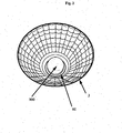
- Fig. 2 the reflector 2 is shown. In the central opening of the reflector 2 sits a cylindrical stray cap 900, which has been handled by the reflector bottom 60.
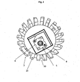
- Fig. 3 is a detailed view of the cup-shaped heat sink 3.
- the LED module 5 is added.
- the side wall of the cup-shaped heat sink 3 has cooling fins 20, which are spaced apart by chimney-like cavities 30. At least in a lower region (i.e., in the direction of the closed base), the cooling fins 20 may be connected by radially inwardly offset wall surfaces. In the upper region, the cooling ribs may be free of fingerprints, in such a way that the reflector outer wall is partially exposed to the outside in a lateral view.
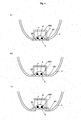
- Fig. 4 shows a cross-sectional view of the positioning possibilities of the reflector 2 / reflector base 60 and the LED module 5 / the scattering cap 900 in an LED emitter according to the invention.
- the reflector bottom 60 may be connected to the side of the carrier 6 with the LED module 5 ( Fig. 4 B).
- Fig. 4C shows a further embodiment of the solution.
- the reflector 2 is connected to the rear side of the LED module 5.
- the reflector bottom 60 may be completely or partially hidden by the LED module 5 (or LED carrier 6). Other other positioning options are also conceivable.
Landscapes
- Engineering & Computer Science (AREA)
- General Engineering & Computer Science (AREA)
- Physics & Mathematics (AREA)
- Microelectronics & Electronic Packaging (AREA)
- Optics & Photonics (AREA)
- Non-Portable Lighting Devices Or Systems Thereof (AREA)
- Led Device Packages (AREA)
Claims (25)
- Projecteur à LED, de préférence pour lumière blanche, comportant :- un module LED (5) avec plusieurs chips LED (7, 7') sur un support (6),- un milieu transparent à la lumière (8) sous lequel les chips LED (7, 7') sont logés,- un réflecteur (2) entourant latéralement les chips LED (7, 7'), dans lequel le réflecteur (2) contient une calotte de diffusion (900) entourant les chips LED (7, 7'), caractérisé en ce que la calotte de diffusion (900) présente une douille dans laquelle est fixée le réflecteur (2) et, par conséquent, la calotte de diffusion (900) est positionnée/attachée.
- Projecteur à LED selon la revendication 1, caractérisé en ce que la calotte de diffusion (900) et le fond du réflecteur (60) se situent dans le même plan.
- Projecteur à LED selon les revendications 1 ou 2, caractérisé en ce que le projecteur à LED a un corps de refroidissement (3) en contact thermique avec le module LED (5).
- Projecteur à LED selon les revendications 1 à 3, caractérisé en ce que la calotte de diffusion (900) et le réflecteur (2) sont séparés ou intégrés.
- Projecteur à LED selon l'une quelconque des revendications précédentes, caractérisé en ce que le milieu transparent à la lumière (8) a une matière luminescente et/ou des particules diffusantes.
- Projecteur à LED selon l'une quelconque des revendications précédentes, caractérisé en ce que la calotte de diffusion (900) présente une forme similaire à un cylindre creux avec une épaisseur de cloison de 1 à 3 mm.
- Projecteur à LED selon la revendication 6, caractérisé en ce que la calotte de diffusion (900) présente une forme similaire à un cylindre creux avec une hauteur de 3 à 10 mm et un diamètre de 3 à 8 mm.
- Projecteur à LED selon l'une quelconque des revendications précédentes, caractérisé en ce que le fond du réflecteur (60) a une ouverture centrale par laquelle les chips LED (7,7') s'élancent dans la calotte de diffusion (900) provenant du support (6) du module LED (5) placé sous le fond du réflecteur (60).
- Projecteur à LED selon l'une quelconque des revendications précédentes, caractérisé en ce qu'une calotte de diffusion (900), de préférence en configuration monobloc avec celui-ci, s'éloigne du fond du réflecteur (60).
- Projecteur à LED selon l'une quelconque des revendications précédentes, caractérisé en ce que la calotte de diffusion (900) et le réflecteur (2) sont fixés sur le support (6) du module LED (5).
- Projecteur à LED selon l'une quelconque des revendications précédentes, caractérisé en ce que les chips LED (7, 7') sont couverts avec ou par un dôme (8) posé par un procédé de distribution ou par un autre couvercle.
- Projecteur à LED selon l'une quelconque des revendications précédentes, caractérisé en ce que les chips LED (7, 7') sont monochromes ou de différentes couleurs.
- Projecteur à LED selon l'une quelconque des revendications précédentes, caractérisé en ce que la surface latérale interne (70) du réflecteur (2) présente un développement parabolique, circulaire ou linéaire ou est configurée, au moins partiellement, sous la forme de facettes.
- Projecteur à LED selon l'une quelconque des revendications précédentes, caractérisé en ce que la surface latérale (70) du réflecteur (2) et/ou la zone superficielle interne (903) et/ou externe (902) de la calotte de diffusion (900) sont configurées en réflexion, en dispersion ou en dispersion-réflexion.
- Projecteur à LED selon l'une quelconque des revendications précédentes, caractérisé en ce que la calotte de diffusion (900) consiste en une matière synthétique remplie de particules diffusantes.
- Projecteur à LED selon l'une quelconque des revendications précédentes, caractérisé en ce que la zone superficielle interne (903) et/ou externe (902) de la calotte de diffusion (900) ont des particules diffusantes et/ou des particules en matière luminescente.
- Projecteur à LED selon l'une quelconque des revendications précédentes, caractérisé en ce que la zone superficielle interne (903) de la calotte de diffusion (900) a des particules en matière luminescente, et la zone superficielle externe (902) de la calotte de diffusion (900) a des particules diffusantes.
- Projecteur à LED selon l'une quelconque des revendications précédentes, caractérisé en ce que la calotte de diffusion (900) a un contact à pression (901).
- Projecteur à LED selon l'une quelconque des revendications précédentes, caractérisé en ce que le fond du réflecteur (60) et/ou la zone de base (50) de la calotte de diffusion (50) ont une forme circulaire, elliptique ou carrée.
- Projecteur à LED selon l'une quelconque des revendications précédentes, caractérisé en ce que le réflecteur (2) est couvert par un disque diffusant ou à conversion de couleur (100) ou est ouvert.
- Projecteur à LED selon l'une quelconque des revendications précédentes, caractérisé en ce qu'il est configuré comme projecteur plafonnier pour une installation en faux-plafonds.
- Projecteur à LED selon l'une quelconque des revendications précédentes, caractérisé en ce qu'il est configuré comme lampe réflecteur à LED rétro-fit et est équipé, par exemple, d'un raccord disponible dans le commerce, comme un pas de vis, une fiche femelle, etc.
- Méthode pour améliorer l'homogénéité de couleur d'un projecteur à LED, comportant les étapes suivantes :- placer plusieurs chips LED (7, 7') sur un support (6),- appliquer un milieu transparent à la lumière (8) sur les chips LED (7, 7'),- faire passer le support (6) depuis l'extérieur par une ouverture centrale dans un fond (60) d'un réflecteur (2) de sorte qu'au moins une partie des chips LED (7, 7') s'élance à l'intérieur du réflecteur (2), et- fixer une calotte de diffusion (900) sur le support (6), dans laquelle la calotte de diffusion (900) présente une douille dans laquelle est fixée le réflecteur (2) et, par conséquent, la calotte de diffusion (900) est positionnée/attachée de sorte que la calotte de diffusion (900) entoure les chips LED (7, 7').
- Méthode pour améliorer l'homogénéité de couleur d'un projecteur à LED selon la revendication 23, dans laquelle le milieu transparent à la lumière (8) est appliqué sur les chips LED (7, 7') par un procédé de distribution, par un procédé d'injection ou par un procédé de surmoulage.
- Méthode pour améliorer l'homogénéité de couleur d'un projecteur à LED selon les revendications 23 ou 24, comportant les étapes complémentaires suivantes :- recouvrir une zone superficielle interne (903) de la calotte de diffusion (900) de particules en matière luminescente, et- recouvrir une zone superficielle externe (902) de la calotte de diffusion (900) de particules diffusantes.
Applications Claiming Priority (2)
| Application Number | Priority Date | Filing Date | Title |
|---|---|---|---|
| ATGM746/2010U AT12552U1 (de) | 2010-12-03 | 2010-12-03 | Led-strahler mit reflektor |
| PCT/AT2011/000484 WO2012071598A2 (fr) | 2010-12-03 | 2011-12-02 | Projecteur à led comportant un réflecteur |
Publications (2)
| Publication Number | Publication Date |
|---|---|
| EP2646740A2 EP2646740A2 (fr) | 2013-10-09 |
| EP2646740B1 true EP2646740B1 (fr) | 2015-08-26 |
Family
ID=45558442
Family Applications (1)
| Application Number | Title | Priority Date | Filing Date |
|---|---|---|---|
| EP11815431.9A Active EP2646740B1 (fr) | 2010-12-03 | 2011-12-02 | Projecteur à led comportant un réflecteur |
Country Status (3)
| Country | Link |
|---|---|
| EP (1) | EP2646740B1 (fr) |
| AT (1) | AT12552U1 (fr) |
| WO (1) | WO2012071598A2 (fr) |
Families Citing this family (5)
| Publication number | Priority date | Publication date | Assignee | Title |
|---|---|---|---|---|
| DE102015101947A1 (de) | 2015-02-11 | 2016-08-11 | Trilux Gmbh & Co. Kg | Langgestreckte Optik für LED-Module |
| US10683971B2 (en) | 2015-04-30 | 2020-06-16 | Cree, Inc. | Solid state lighting components |
| EP3317579B1 (fr) * | 2015-06-30 | 2020-08-19 | Signify Holding B.V. | Spot à del avec forme, couleur et uniformité de couleur de faisceau personnalisable |
| US11433154B2 (en) | 2020-05-18 | 2022-09-06 | Wangs Alliance Corporation | Germicidal lighting |
| US11027038B1 (en) | 2020-05-22 | 2021-06-08 | Delta T, Llc | Fan for improving air quality |
Citations (4)
| Publication number | Priority date | Publication date | Assignee | Title |
|---|---|---|---|---|
| US20080310158A1 (en) * | 2007-06-18 | 2008-12-18 | Xicato, Inc. | Solid State Illumination Device |
| DE102007054206A1 (de) * | 2007-10-15 | 2009-04-16 | Harald Hofmann | LED-Lampe mit Diffusor |
| WO2010106504A1 (fr) * | 2009-03-19 | 2010-09-23 | Koninklijke Philips Electronics N.V. | Dispositif d'éclairage avec matériau luminescent à distance |
| WO2010113098A1 (fr) * | 2009-04-02 | 2010-10-07 | Koninklijke Philips Electronics N.V. | Réflecteur à chambre de mélange |
Family Cites Families (7)
| Publication number | Priority date | Publication date | Assignee | Title |
|---|---|---|---|---|
| US6547416B2 (en) | 2000-12-21 | 2003-04-15 | Koninklijke Philips Electronics N.V. | Faceted multi-chip package to provide a beam of uniform white light from multiple monochrome LEDs |
| DE10105957A1 (de) * | 2001-02-09 | 2002-09-19 | Fraunhofer Ges Forschung | Verfahren zur Herstellung von Licht streuenden Elementen |
| CN1981157B (zh) * | 2004-05-05 | 2011-03-16 | 伦斯勒工业学院 | 使用固态发射器和降频转换材料的高效光源 |
| EP1693615A1 (fr) * | 2005-02-22 | 2006-08-23 | Moduled Inc. | Dispositif d'éclairage avec une unité de mélange |
| DE102006043402B4 (de) * | 2006-09-15 | 2019-05-09 | Osram Gmbh | Beleuchtungseinheit mit einem optischen Element |
| EP2289116A1 (fr) * | 2008-06-26 | 2011-03-02 | Osram-Sylvania Inc. | Lampe à diodes électroluminescentes avec revêtement au phosphore à distance et procédé de fabrication de la lampe |
| US8613530B2 (en) * | 2010-01-11 | 2013-12-24 | General Electric Company | Compact light-mixing LED light engine and white LED lamp with narrow beam and high CRI using same |
-
2010
- 2010-12-03 AT ATGM746/2010U patent/AT12552U1/de not_active IP Right Cessation
-
2011
- 2011-12-02 WO PCT/AT2011/000484 patent/WO2012071598A2/fr not_active Ceased
- 2011-12-02 EP EP11815431.9A patent/EP2646740B1/fr active Active
Patent Citations (4)
| Publication number | Priority date | Publication date | Assignee | Title |
|---|---|---|---|---|
| US20080310158A1 (en) * | 2007-06-18 | 2008-12-18 | Xicato, Inc. | Solid State Illumination Device |
| DE102007054206A1 (de) * | 2007-10-15 | 2009-04-16 | Harald Hofmann | LED-Lampe mit Diffusor |
| WO2010106504A1 (fr) * | 2009-03-19 | 2010-09-23 | Koninklijke Philips Electronics N.V. | Dispositif d'éclairage avec matériau luminescent à distance |
| WO2010113098A1 (fr) * | 2009-04-02 | 2010-10-07 | Koninklijke Philips Electronics N.V. | Réflecteur à chambre de mélange |
Also Published As
| Publication number | Publication date |
|---|---|
| WO2012071598A2 (fr) | 2012-06-07 |
| AT12552U1 (de) | 2012-07-15 |
| WO2012071598A3 (fr) | 2012-08-30 |
| EP2646740A2 (fr) | 2013-10-09 |
Similar Documents
| Publication | Publication Date | Title |
|---|---|---|
| DE102010043921B4 (de) | Leuchtvorrichtung und Verfahren zum Herstellen einer Leuchtvorrichtung | |
| WO2011067093A1 (fr) | Dispositif d'éclairage et élément rapporté à fixer au dispositif d'éclairage | |
| EP2646740B1 (fr) | Projecteur à led comportant un réflecteur | |
| WO2012123233A2 (fr) | Dispositif d'éclairage | |
| EP2264796A2 (fr) | DEL blanche avec un réflecteur conique et facettes planes | |
| EP1843081B1 (fr) | Eclairage, en particulier éclairage d'intérieur | |
| DE102010029515A1 (de) | Halbleiterlampe, Verfahren zum Herstellen eines Kolbens für eine Halbleiterlampe und Verfahren zum Herstellen einer Halbleiterlampe | |
| DE102009047487A1 (de) | Leuchtmodul | |
| EP2556286B1 (fr) | Module à del à double diffuseur | |
| EP2627942B1 (fr) | Projecteur à diodes électroluminescentes doté d'un réflecteur | |
| DE102009047481A1 (de) | Leuchtmodul | |
| DE102012209354A1 (de) | LED-Modul | |
| DE102011007214B4 (de) | Kolben für Halbleiter - Leuchtvorrichtung sowie Halbleiter - Leuchtvorrichtung | |
| DE102011076300A1 (de) | Leuchtvorrichtung mit aufsatzelement | |
| AT15662U1 (de) | Rahmenlose Pendelleuchte | |
| WO2012062643A1 (fr) | Dispositif d'éclairage et procédé de fabrication d'un tel dispositif | |
| DE102017222649A1 (de) | Lichtmodul, anordnung, scheinwerfer und verfahren | |
| DE202010007032U1 (de) | LED-Modul für Strahler | |
| AT13039U1 (de) | Reflektoreinheit für leds, led lichtquelle, poster-box sowie verfahren zur montage der led lichtquelle | |
| EP2250433B1 (fr) | Lampe, en particulier à éclairage dirigé vers le bas | |
| EP2816275B1 (fr) | Module à DEL pour montage sans outil d'éléments optiques | |
| DE102016203668A1 (de) | Retrofitlampe | |
| DE102014205153B4 (de) | Halbleiterlampe | |
| DE102019102056B4 (de) | Reflektorlampe mit dreidimensionaler Lightengine | |
| EP3022481A1 (fr) | Unité d'éclairage pourvue d'un composant électroluminescent |
Legal Events
| Date | Code | Title | Description |
|---|---|---|---|
| PUAI | Public reference made under article 153(3) epc to a published international application that has entered the european phase |
Free format text: ORIGINAL CODE: 0009012 |
|
| 17P | Request for examination filed |
Effective date: 20130603 |
|
| AK | Designated contracting states |
Kind code of ref document: A2 Designated state(s): AL AT BE BG CH CY CZ DE DK EE ES FI FR GB GR HR HU IE IS IT LI LT LU LV MC MK MT NL NO PL PT RO RS SE SI SK SM TR |
|
| DAX | Request for extension of the european patent (deleted) | ||
| 17Q | First examination report despatched |
Effective date: 20140313 |
|
| RAP1 | Party data changed (applicant data changed or rights of an application transferred) |
Owner name: LUMITECH PRODUKTION UND ENTWICKLUNG GMBH Owner name: TRIDONIC JENNERSDORF GMBH |
|
| GRAP | Despatch of communication of intention to grant a patent |
Free format text: ORIGINAL CODE: EPIDOSNIGR1 |
|
| RIC1 | Information provided on ipc code assigned before grant |
Ipc: F21K 99/00 20100101AFI20150306BHEP Ipc: F21V 3/04 20060101ALI20150306BHEP Ipc: F21Y 101/02 20060101ALN20150306BHEP Ipc: F21V 13/02 20060101ALN20150306BHEP Ipc: F21Y 113/00 20060101ALN20150306BHEP |
|
| INTG | Intention to grant announced |
Effective date: 20150401 |
|
| GRAS | Grant fee paid |
Free format text: ORIGINAL CODE: EPIDOSNIGR3 |
|
| GRAA | (expected) grant |
Free format text: ORIGINAL CODE: 0009210 |
|
| AK | Designated contracting states |
Kind code of ref document: B1 Designated state(s): AL AT BE BG CH CY CZ DE DK EE ES FI FR GB GR HR HU IE IS IT LI LT LU LV MC MK MT NL NO PL PT RO RS SE SI SK SM TR |
|
| REG | Reference to a national code |
Ref country code: GB Ref legal event code: FG4D Free format text: NOT ENGLISH |
|
| REG | Reference to a national code |
Ref country code: CH Ref legal event code: EP |
|
| REG | Reference to a national code |
Ref country code: AT Ref legal event code: REF Ref document number: 745401 Country of ref document: AT Kind code of ref document: T Effective date: 20150915 |
|
| REG | Reference to a national code |
Ref country code: IE Ref legal event code: FG4D Free format text: LANGUAGE OF EP DOCUMENT: GERMAN |
|
| REG | Reference to a national code |
Ref country code: DE Ref legal event code: R096 Ref document number: 502011007728 Country of ref document: DE |
|
| REG | Reference to a national code |
Ref country code: CH Ref legal event code: NV Representative=s name: WEINMANN ZIMMERLI, CH |
|
| REG | Reference to a national code |
Ref country code: FR Ref legal event code: PLFP Year of fee payment: 5 |
|
| REG | Reference to a national code |
Ref country code: LT Ref legal event code: MG4D |
|
| PG25 | Lapsed in a contracting state [announced via postgrant information from national office to epo] |
Ref country code: FI Free format text: LAPSE BECAUSE OF FAILURE TO SUBMIT A TRANSLATION OF THE DESCRIPTION OR TO PAY THE FEE WITHIN THE PRESCRIBED TIME-LIMIT Effective date: 20150826 Ref country code: GR Free format text: LAPSE BECAUSE OF FAILURE TO SUBMIT A TRANSLATION OF THE DESCRIPTION OR TO PAY THE FEE WITHIN THE PRESCRIBED TIME-LIMIT Effective date: 20151127 Ref country code: NO Free format text: LAPSE BECAUSE OF FAILURE TO SUBMIT A TRANSLATION OF THE DESCRIPTION OR TO PAY THE FEE WITHIN THE PRESCRIBED TIME-LIMIT Effective date: 20151126 Ref country code: LT Free format text: LAPSE BECAUSE OF FAILURE TO SUBMIT A TRANSLATION OF THE DESCRIPTION OR TO PAY THE FEE WITHIN THE PRESCRIBED TIME-LIMIT Effective date: 20150826 Ref country code: LV Free format text: LAPSE BECAUSE OF FAILURE TO SUBMIT A TRANSLATION OF THE DESCRIPTION OR TO PAY THE FEE WITHIN THE PRESCRIBED TIME-LIMIT Effective date: 20150826 |
|
| REG | Reference to a national code |
Ref country code: NL Ref legal event code: MP Effective date: 20150826 |
|
| PG25 | Lapsed in a contracting state [announced via postgrant information from national office to epo] |
Ref country code: SE Free format text: LAPSE BECAUSE OF FAILURE TO SUBMIT A TRANSLATION OF THE DESCRIPTION OR TO PAY THE FEE WITHIN THE PRESCRIBED TIME-LIMIT Effective date: 20150826 Ref country code: PL Free format text: LAPSE BECAUSE OF FAILURE TO SUBMIT A TRANSLATION OF THE DESCRIPTION OR TO PAY THE FEE WITHIN THE PRESCRIBED TIME-LIMIT Effective date: 20150826 Ref country code: RS Free format text: LAPSE BECAUSE OF FAILURE TO SUBMIT A TRANSLATION OF THE DESCRIPTION OR TO PAY THE FEE WITHIN THE PRESCRIBED TIME-LIMIT Effective date: 20150826 Ref country code: ES Free format text: LAPSE BECAUSE OF FAILURE TO SUBMIT A TRANSLATION OF THE DESCRIPTION OR TO PAY THE FEE WITHIN THE PRESCRIBED TIME-LIMIT Effective date: 20150826 Ref country code: PT Free format text: LAPSE BECAUSE OF FAILURE TO SUBMIT A TRANSLATION OF THE DESCRIPTION OR TO PAY THE FEE WITHIN THE PRESCRIBED TIME-LIMIT Effective date: 20151228 Ref country code: IS Free format text: LAPSE BECAUSE OF FAILURE TO SUBMIT A TRANSLATION OF THE DESCRIPTION OR TO PAY THE FEE WITHIN THE PRESCRIBED TIME-LIMIT Effective date: 20151226 Ref country code: HR Free format text: LAPSE BECAUSE OF FAILURE TO SUBMIT A TRANSLATION OF THE DESCRIPTION OR TO PAY THE FEE WITHIN THE PRESCRIBED TIME-LIMIT Effective date: 20150826 |
|
| PG25 | Lapsed in a contracting state [announced via postgrant information from national office to epo] |
Ref country code: NL Free format text: LAPSE BECAUSE OF FAILURE TO SUBMIT A TRANSLATION OF THE DESCRIPTION OR TO PAY THE FEE WITHIN THE PRESCRIBED TIME-LIMIT Effective date: 20150826 |
|
| PG25 | Lapsed in a contracting state [announced via postgrant information from national office to epo] |
Ref country code: SK Free format text: LAPSE BECAUSE OF FAILURE TO SUBMIT A TRANSLATION OF THE DESCRIPTION OR TO PAY THE FEE WITHIN THE PRESCRIBED TIME-LIMIT Effective date: 20150826 Ref country code: CZ Free format text: LAPSE BECAUSE OF FAILURE TO SUBMIT A TRANSLATION OF THE DESCRIPTION OR TO PAY THE FEE WITHIN THE PRESCRIBED TIME-LIMIT Effective date: 20150826 Ref country code: DK Free format text: LAPSE BECAUSE OF FAILURE TO SUBMIT A TRANSLATION OF THE DESCRIPTION OR TO PAY THE FEE WITHIN THE PRESCRIBED TIME-LIMIT Effective date: 20150826 Ref country code: EE Free format text: LAPSE BECAUSE OF FAILURE TO SUBMIT A TRANSLATION OF THE DESCRIPTION OR TO PAY THE FEE WITHIN THE PRESCRIBED TIME-LIMIT Effective date: 20150826 Ref country code: IT Free format text: LAPSE BECAUSE OF FAILURE TO SUBMIT A TRANSLATION OF THE DESCRIPTION OR TO PAY THE FEE WITHIN THE PRESCRIBED TIME-LIMIT Effective date: 20150826 |
|
| REG | Reference to a national code |
Ref country code: DE Ref legal event code: R097 Ref document number: 502011007728 Country of ref document: DE |
|
| PG25 | Lapsed in a contracting state [announced via postgrant information from national office to epo] |
Ref country code: BE Free format text: LAPSE BECAUSE OF NON-PAYMENT OF DUE FEES Effective date: 20151231 Ref country code: RO Free format text: LAPSE BECAUSE OF FAILURE TO SUBMIT A TRANSLATION OF THE DESCRIPTION OR TO PAY THE FEE WITHIN THE PRESCRIBED TIME-LIMIT Effective date: 20150826 |
|
| PLBE | No opposition filed within time limit |
Free format text: ORIGINAL CODE: 0009261 |
|
| STAA | Information on the status of an ep patent application or granted ep patent |
Free format text: STATUS: NO OPPOSITION FILED WITHIN TIME LIMIT |
|
| PG25 | Lapsed in a contracting state [announced via postgrant information from national office to epo] |
Ref country code: MC Free format text: LAPSE BECAUSE OF FAILURE TO SUBMIT A TRANSLATION OF THE DESCRIPTION OR TO PAY THE FEE WITHIN THE PRESCRIBED TIME-LIMIT Effective date: 20150826 Ref country code: LU Free format text: LAPSE BECAUSE OF FAILURE TO SUBMIT A TRANSLATION OF THE DESCRIPTION OR TO PAY THE FEE WITHIN THE PRESCRIBED TIME-LIMIT Effective date: 20151202 |
|
| 26N | No opposition filed |
Effective date: 20160530 |
|
| PG25 | Lapsed in a contracting state [announced via postgrant information from national office to epo] |
Ref country code: SI Free format text: LAPSE BECAUSE OF FAILURE TO SUBMIT A TRANSLATION OF THE DESCRIPTION OR TO PAY THE FEE WITHIN THE PRESCRIBED TIME-LIMIT Effective date: 20150826 |
|
| REG | Reference to a national code |
Ref country code: IE Ref legal event code: MM4A |
|
| PG25 | Lapsed in a contracting state [announced via postgrant information from national office to epo] |
Ref country code: IE Free format text: LAPSE BECAUSE OF NON-PAYMENT OF DUE FEES Effective date: 20151202 |
|
| REG | Reference to a national code |
Ref country code: FR Ref legal event code: PLFP Year of fee payment: 6 |
|
| PG25 | Lapsed in a contracting state [announced via postgrant information from national office to epo] |
Ref country code: SM Free format text: LAPSE BECAUSE OF FAILURE TO SUBMIT A TRANSLATION OF THE DESCRIPTION OR TO PAY THE FEE WITHIN THE PRESCRIBED TIME-LIMIT Effective date: 20150826 Ref country code: BG Free format text: LAPSE BECAUSE OF FAILURE TO SUBMIT A TRANSLATION OF THE DESCRIPTION OR TO PAY THE FEE WITHIN THE PRESCRIBED TIME-LIMIT Effective date: 20150826 Ref country code: HU Free format text: LAPSE BECAUSE OF FAILURE TO SUBMIT A TRANSLATION OF THE DESCRIPTION OR TO PAY THE FEE WITHIN THE PRESCRIBED TIME-LIMIT; INVALID AB INITIO Effective date: 20111202 |
|
| PG25 | Lapsed in a contracting state [announced via postgrant information from national office to epo] |
Ref country code: CY Free format text: LAPSE BECAUSE OF FAILURE TO SUBMIT A TRANSLATION OF THE DESCRIPTION OR TO PAY THE FEE WITHIN THE PRESCRIBED TIME-LIMIT Effective date: 20150826 |
|
| PG25 | Lapsed in a contracting state [announced via postgrant information from national office to epo] |
Ref country code: MT Free format text: LAPSE BECAUSE OF FAILURE TO SUBMIT A TRANSLATION OF THE DESCRIPTION OR TO PAY THE FEE WITHIN THE PRESCRIBED TIME-LIMIT Effective date: 20150826 |
|
| REG | Reference to a national code |
Ref country code: FR Ref legal event code: PLFP Year of fee payment: 7 |
|
| PG25 | Lapsed in a contracting state [announced via postgrant information from national office to epo] |
Ref country code: TR Free format text: LAPSE BECAUSE OF FAILURE TO SUBMIT A TRANSLATION OF THE DESCRIPTION OR TO PAY THE FEE WITHIN THE PRESCRIBED TIME-LIMIT Effective date: 20150826 Ref country code: MK Free format text: LAPSE BECAUSE OF FAILURE TO SUBMIT A TRANSLATION OF THE DESCRIPTION OR TO PAY THE FEE WITHIN THE PRESCRIBED TIME-LIMIT Effective date: 20150826 |
|
| PG25 | Lapsed in a contracting state [announced via postgrant information from national office to epo] |
Ref country code: AL Free format text: LAPSE BECAUSE OF FAILURE TO SUBMIT A TRANSLATION OF THE DESCRIPTION OR TO PAY THE FEE WITHIN THE PRESCRIBED TIME-LIMIT Effective date: 20150826 |
|
| REG | Reference to a national code |
Ref country code: CH Ref legal event code: PK Free format text: BERICHTIGUNGEN |
|
| RIC2 | Information provided on ipc code assigned after grant |
Ipc: F21V 3/04 20180101ALI20150306BHEP Ipc: F21Y 101/02 20000101ALN20150306BHEP Ipc: F21Y 113/00 20160101ALN20150306BHEP Ipc: F21K 99/00 20160101AFI20150306BHEP Ipc: F21V 13/02 20060101ALN20150306BHEP |
|
| REG | Reference to a national code |
Ref country code: DE Ref legal event code: R081 Ref document number: 502011007728 Country of ref document: DE Owner name: TRIDONIC GMBH & CO KG, AT Free format text: FORMER OWNERS: LUMITECH PRODUKTION UND ENTWICKLUNG GMBH, JENNERSDORF, AT; TRIDONIC JENNERSDORF GMBH, JENNERSDORF, AT Ref country code: DE Ref legal event code: R082 Ref document number: 502011007728 Country of ref document: DE Representative=s name: MITSCHERLICH, PATENT- UND RECHTSANWAELTE PARTM, DE Ref country code: DE Ref legal event code: R081 Ref document number: 502011007728 Country of ref document: DE Owner name: LUMITECH PATENTVERWERTUNG GMBH, AT Free format text: FORMER OWNERS: LUMITECH PRODUKTION UND ENTWICKLUNG GMBH, JENNERSDORF, AT; TRIDONIC JENNERSDORF GMBH, JENNERSDORF, AT Ref country code: DE Ref legal event code: R081 Ref document number: 502011007728 Country of ref document: DE Owner name: TRIDONIC JENNERSDORF GMBH, AT Free format text: FORMER OWNERS: LUMITECH PRODUKTION UND ENTWICKLUNG GMBH, JENNERSDORF, AT; TRIDONIC JENNERSDORF GMBH, JENNERSDORF, AT |
|
| REG | Reference to a national code |
Ref country code: DE Ref legal event code: R084 Ref document number: 502011007728 Country of ref document: DE |
|
| PGFP | Annual fee paid to national office [announced via postgrant information from national office to epo] |
Ref country code: FR Payment date: 20191224 Year of fee payment: 9 |
|
| PGFP | Annual fee paid to national office [announced via postgrant information from national office to epo] |
Ref country code: AT Payment date: 20191220 Year of fee payment: 9 |
|
| REG | Reference to a national code |
Ref country code: AT Ref legal event code: PC Ref document number: 745401 Country of ref document: AT Kind code of ref document: T Owner name: TRIDONIC JENNERSDORF GMBH, AT Effective date: 20200305 Ref country code: AT Ref legal event code: PC Ref document number: 745401 Country of ref document: AT Kind code of ref document: T Owner name: LUMITECH PATENTVERWERTUNG GMBH, AT Effective date: 20200305 |
|
| PGFP | Annual fee paid to national office [announced via postgrant information from national office to epo] |
Ref country code: CH Payment date: 20200113 Year of fee payment: 9 |
|
| REG | Reference to a national code |
Ref country code: CH Ref legal event code: PL |
|
| REG | Reference to a national code |
Ref country code: AT Ref legal event code: MM01 Ref document number: 745401 Country of ref document: AT Kind code of ref document: T Effective date: 20201202 |
|
| PG25 | Lapsed in a contracting state [announced via postgrant information from national office to epo] |
Ref country code: AT Free format text: LAPSE BECAUSE OF NON-PAYMENT OF DUE FEES Effective date: 20201202 Ref country code: FR Free format text: LAPSE BECAUSE OF NON-PAYMENT OF DUE FEES Effective date: 20201231 |
|
| PG25 | Lapsed in a contracting state [announced via postgrant information from national office to epo] |
Ref country code: CH Free format text: LAPSE BECAUSE OF NON-PAYMENT OF DUE FEES Effective date: 20201231 Ref country code: LI Free format text: LAPSE BECAUSE OF NON-PAYMENT OF DUE FEES Effective date: 20201231 |
|
| REG | Reference to a national code |
Ref country code: DE Ref legal event code: R081 Ref document number: 502011007728 Country of ref document: DE Owner name: TRIDONIC GMBH & CO KG, AT Free format text: FORMER OWNERS: LUMITECH PATENTVERWERTUNG GMBH, JENNERSDORF, AT; TRIDONIC JENNERSDORF GMBH, JENNERSDORF, AT Ref country code: DE Ref legal event code: R081 Ref document number: 502011007728 Country of ref document: DE Owner name: LUMITECH PATENTVERWERTUNG GMBH, AT Free format text: FORMER OWNERS: LUMITECH PATENTVERWERTUNG GMBH, JENNERSDORF, AT; TRIDONIC JENNERSDORF GMBH, JENNERSDORF, AT |
|
| PGFP | Annual fee paid to national office [announced via postgrant information from national office to epo] |
Ref country code: GB Payment date: 20221220 Year of fee payment: 12 |
|
| P01 | Opt-out of the competence of the unified patent court (upc) registered |
Effective date: 20231130 |
|
| GBPC | Gb: european patent ceased through non-payment of renewal fee |
Effective date: 20231202 |
|
| PG25 | Lapsed in a contracting state [announced via postgrant information from national office to epo] |
Ref country code: GB Free format text: LAPSE BECAUSE OF NON-PAYMENT OF DUE FEES Effective date: 20231202 |
|
| PG25 | Lapsed in a contracting state [announced via postgrant information from national office to epo] |
Ref country code: GB Free format text: LAPSE BECAUSE OF NON-PAYMENT OF DUE FEES Effective date: 20231202 |
|
| PGFP | Annual fee paid to national office [announced via postgrant information from national office to epo] |
Ref country code: DE Payment date: 20241227 Year of fee payment: 14 |