EP2646775B1 - Verfahren und system zur schätzung des weges eines mobilen elements oder körpers - Google Patents
Verfahren und system zur schätzung des weges eines mobilen elements oder körpers Download PDFInfo
- Publication number
- EP2646775B1 EP2646775B1 EP11805078.0A EP11805078A EP2646775B1 EP 2646775 B1 EP2646775 B1 EP 2646775B1 EP 11805078 A EP11805078 A EP 11805078A EP 2646775 B1 EP2646775 B1 EP 2646775B1
- Authority
- EP
- European Patent Office
- Prior art keywords
- estimating
- path
- accelerometer
- trajectory
- correction
- Prior art date
- Legal status (The legal status is an assumption and is not a legal conclusion. Google has not performed a legal analysis and makes no representation as to the accuracy of the status listed.)
- Active
Links
Images


Classifications
-
- G—PHYSICS
- G01—MEASURING; TESTING
- G01C—MEASURING DISTANCES, LEVELS OR BEARINGS; SURVEYING; NAVIGATION; GYROSCOPIC INSTRUMENTS; PHOTOGRAMMETRY OR VIDEOGRAMMETRY
- G01C21/00—Navigation; Navigational instruments not provided for in groups G01C1/00 - G01C19/00
- G01C21/005—Navigation; Navigational instruments not provided for in groups G01C1/00 - G01C19/00 with correlation of navigation data from several sources, e.g. map or contour matching
-
- G—PHYSICS
- G01—MEASURING; TESTING
- G01C—MEASURING DISTANCES, LEVELS OR BEARINGS; SURVEYING; NAVIGATION; GYROSCOPIC INSTRUMENTS; PHOTOGRAMMETRY OR VIDEOGRAMMETRY
- G01C21/00—Navigation; Navigational instruments not provided for in groups G01C1/00 - G01C19/00
- G01C21/20—Instruments for performing navigational calculations
- G01C21/206—Instruments for performing navigational calculations specially adapted for indoor navigation
-
- G—PHYSICS
- G01—MEASURING; TESTING
- G01P—MEASURING LINEAR OR ANGULAR SPEED, ACCELERATION, DECELERATION, OR SHOCK; INDICATING PRESENCE, ABSENCE, OR DIRECTION, OF MOVEMENT
- G01P15/00—Measuring acceleration; Measuring deceleration; Measuring shock, i.e. sudden change of acceleration
- G01P15/02—Measuring acceleration; Measuring deceleration; Measuring shock, i.e. sudden change of acceleration by making use of inertia forces using solid seismic masses
- G01P15/08—Measuring acceleration; Measuring deceleration; Measuring shock, i.e. sudden change of acceleration by making use of inertia forces using solid seismic masses with conversion into electric or magnetic values
- G01P15/0891—Measuring acceleration; Measuring deceleration; Measuring shock, i.e. sudden change of acceleration by making use of inertia forces using solid seismic masses with conversion into electric or magnetic values with indication of predetermined acceleration values
Definitions
- the invention relates to a system for estimating a trajectory of a mobile element or body comprising a sensor assembly comprising an accelerometer and a gyrometer bound together.
- the trajectory of an element is a set of successive Cartesian positions Position_C of the element.
- the invention particularly relates to the estimation of this trajectory or orientation in the context of pedestrian navigation.
- This field is in full expansion, with at least one international conference fully dedicated to the field of navigation and location within buildings (International Conference on Indoor Positioning and Indoor Navigation - IPIN, articles published in IEEE Xplore).
- the invention lies in a context with two measurement modes, namely accelerometers and gyrometers (AG).
- the reference mark is the North mark for "North Frame” in English, which is a fixed landmark in the land referential. This marker is used throughout the movement (walk or run). It is considered as the reference mark: the orientations (angular position) and positions (Cartesian position) are measured with respect to this reference.
- the North coordinate system is defined by its origin O NF and its axes ( x NF , Y NF , Z NF ) which merge with the axes of the terrestrial reference, from east, north and vertical ascending. Its origin O NF may correspond to the place where the movement begins or to any other place.
- the NF navigation mark which is linked to the North mark by a constant rotation around the vertical axis.
- the NF navigation mark is used as a reference mark, and the measurements given in this NF navigation mark have an exponent n.
- the trajectory traversed by the EC sensor assembly can be recovered by a dual integration of the own acceleration at p not in three dimensions or 3D in the NF navigation mark.
- BF be a reference linked to the sensor.
- the vectors expressed in this frame have an exponent b.
- the measurements of the accelerometer are given in the reference BF and gravity (or gravity) is superimposed on the acceleration proper. at p boy Wut .
- the orientation drift is generally expressed as an orientation error of the local coordinate system BF with respect to the NF mark. It can then be considered that an error or drift of the estimated orientation turns the data of the local coordinate system BF, not to the navigation mark NF, but to another navigation mark NF 'affected by the drift and defined in the following of the description.
- the reference NF 'affected by the drift is defined by its orientation relative to the navigation mark or fixed global reference linked to the terrestrial reference NF. This orientation of NF 'with respect to NF is related to the drift of the estimated orientation by integrating the gyrometer. Thus, the orientation of the reference NF 'relative to the NF mark drift slowly over time.
- the measurements given in this reference NF ' have an exponent n'.
- orientation of the NF mark in the NF 'mark is represented by a quaternion qn
- the orientation of the NF mark in the mark BF by a quaternion q bn the orientation of the mark NF' in the mark BF by a quaternion q bn '
- q bn t q bn' t ⁇ q n'n t
- the sign ⁇ being the sign of the product associated with the quaternions.
- the walking cycle can be separated into two phases: the flight phase during which the foot moves (called SW for "SWing phase” in English), and that during which the foot is on the ground or support phase (called ST for "STance phase” in English).
- a step is composed of the succession of the two phases ST and SW and the walk is characterized by a succession of steps.
- R nb l is the rotation matrix associated with the quaternion q nb i as defined by:
- R bn 2 ⁇ q bn , 0 2 - 1 + 2 ⁇ q bn , 1 2 2 ⁇ q bn , 1 ⁇ q bn , 2 - 2 ⁇ q bn , 0 q bn , 3 2 ⁇ q bn , 1 ⁇ q bn , 3 + 2 ⁇ q bn , 0 q bn , 2 2 ⁇ q bn , 1 ⁇ q bn , 2 + 2 ⁇ q bn , 0 q bn , 3 2 ⁇ q bn ,
- the angular positition quaternion q bn l drift with respect to its "true" value due to the drift and noise of gyrometer G measurements.
- the clean acceleration is corrupted due to the drift due to the integration of the gyrometer to obtain the orientation.
- the system implements a procedure for detecting the phase of support or "stance phase” based on fuzzy logic.
- An indirect Kalman filter IKF is implemented (the state is not directly estimated, but an error on the state, as in a fifth article, " Pedestrian Inertial Navigation with Gait Phase Detection Assisted Zero Velocity Updating Young Soo Suh, Sangkyung Park ", 4th International Conference on Autonomous Robots and Agents, Feb 10-12, 2009, Wellington, New Zeal and, where the indirect Kalman filter IKF is implanted in the context of pedestrian navigation, this article using inertial / magnetic sensors and force sensors positioned respectively on the tip of the shoe and under the shoe).
- the constitution of the inertial system is not explicitly described, and a Kalman filter is implemented.
- SLAM algorithm - Simultaneous Location And Mapping is exploited, even if locally, the sensors that make it possible to build the map may be unavailable.
- a ninth article " Pedestrian Indoor Navigation by aiding a Foot-mounted IMU with RFID Signal Strength Measurements ", by Antonio R. Jiménez, Fernando Seco, J. Carlos Prieto and Jorge Guevara, IPIN Conference, Zurich, 2010 , implements an inertial measurement unit attached to a pedestrian's foot and RFID tags.
- the detection of the phases at zero speed is exploited and an inverse Kalman filter is implanted to compensate for the errors of position, speed and attitude or angular position.
- the implanted technique is valid for different types of movement (lateral, backward, walk, run) and does not require an off-line calibration phase or the attenuation of radio signals in the environment. Cape drift is reduced through the use of magnetometers.
- the document FR 2 918 745 proposes a navigation assistance device for a person comprising at least one computer including in memory a digitized map of the place in which the path of the person is provided, a human-machine interface, a set of sensors worn by the person and delivering the information on the movements of the person.
- the set of sensors comprises for example an inertial unit.
- the sensors carried by the user are for example accelerometers, magnetometers, gyrometers, and barometers.
- a computation of the path to be traveled is for example updated according to intermediate objectives identified of the path reached, these objectives being identified on the digitized map. In this case, there is a resetting of the drift to the intermediate objectives.
- the device of the present invention does not require a map of the place. Neither does it require "manual registration" with respect to identified intermediate crossing points.
- the document US20070018890 offers an internal and external navigation device.
- the portable version merges the information provided by several sensors, GPS, pedometers and / or made from accelerometers to two measurement axes, and digital compass. Sensors are placed on the back of an accompanying dog.
- Internal localization is achieved by exploiting the wireless connections already available in many environments due to the existence of WiFi networks. The fusion is performed as part of the Dempster-Shafer theory. The system does not use gyrometers.
- the document EP1488197 combines a GPS device and a Dead Reckoning Unit in the English language, the navigation system being intended for visually impaired people.
- the system also contains a digital camera for capturing images. A scanned map of the environment is also used.
- the Dead Reckoning Unit's Dead Reckoning Unit contains an accelerometer, a gyrometer and a microcontroller; it takes over when the GPS signal is lost or to improve the accuracy of the location obtained by the GPS.
- the DRU makes it possible to estimate the distance traveled and the change of direction, by coupling this information to a digitized map even in the event of loss of the GPS signal. It is possible to locate the user. The distance is estimated from the number of steps taken and the average length of a step.
- the relative direction of the user is estimated using a gyroscope because it is insensitive to magnetic disturbances and is accurate.
- the authors note that other sensors for estimating the distance traveled and the relative change of direction can be exploited and that their device is not limited to the use of an accelerometer and a magnetometer.
- the output of the gyroscope is integrated to give the angle which is coded, for the example presented on four bits, which gives 16 possible values of the angle, and a resolution of 22.5 °.
- the problem of the drift introduced by the integration of the gyrometer is not addressed, probably due to the use of a device incorporating a gyro of high accuracy.
- the patent US6323807 presents an indoor or indoor navigation system with "passive" sensors.
- a first statistical model is constructed from measurements made in known places.
- a second statistical model is obtained from measurements at unknown points.
- the calculator determines the probability that an unknown Cartesian position actually corresponds to a known position.
- the sensors include a triaxial accelerometer, a triaxial magnetometer, a brightness detector, and a temperature sensor. It is also possible to add a low resolution camera, a hygrometry sensor, a gyroscope to measure inclination, a gas detector, and an altimeter. The system requires a learning phase, with extraction of characteristics. It is then akin to a classification system.
- the authors take into account the existing bias in gyro measurements.
- the angle of the tibia relative to the horizontal when the foot is fixed is obtained directly from the measurements provided by the bi-axial accelerometer. From the measurements available at the level of the tibia, the corresponding measurements which should be measured at the level of the ankle are calculated.
- the estimate of the angle bias introduced into the angle calculation by the integration of the measurement provided by the gyroscope implements a low pass filtering by a second order Butterworth filter which is applied to the angle obtained by integration at times when we do not know precisely this angle.
- a single-axis gyroscope is placed on a user's shin near the ankle.
- the inclination of the tibia is obtained by integrating the measurements provided by the gyroscope.
- the initial bias of the gyrometer is obtained by calculating the average value of the signal delivered by the gyrometer when the user is at rest, over a five-second time window.
- the Cartesian position and the orientation or angular position of the foot are estimated from triaxial accelerometric and magnetometric measurements.
- the measurements provided by the gyrometers are integrated to determine the orientation, and the position is obtained by the double integration of the accelerations brought back into the inertial reference frame.
- the angular velocity measurement is integrated and the drift is compensated using the conditions on the angle at the beginning and the end of the pitch.
- the orientation obtained, as a function of time, is then used to express the acceleration in the inertial frame.
- the gravity field is then subtracted, which provides the proper acceleration.
- the latter is integrated twice to determine the position, and the conditions on the beginning and the end of the step are used to eliminate the position drift. This approach of correction of the drift, illustrated by the figure 1 of the seventeenth article, is totally different from that of the present invention.
- the passage of the movable marker to the fixed marker is achieved by using the attitude (given in the form of a quaternion) provided directly by the sensor module, the latter integrating a Kalman filter. The description does not give precise information on the sensors used to calculate this orentation.
- a system for estimating the trajectory of a mobile element or body comprising a sensor assembly comprising an accelerometer and a gyrometer linked together.
- the system comprises means for retroactively correcting an angular position obtained from the gyro measurements at least one of a plurality of successive instants of a time interval from Cartesian positions of the accelerometer to at least one two of said successive instants and predetermined information representative of the trajectory of the accelerometer during said time interval, and from a rotation adapted to minimize a difference between said predetermined information and their equivalent on the trajectory obtained after rotation.
- the predetermined information may relate to the orientation of the trajectory. This orientation can be calculated from the estimated trajectory. For example, if the predetermined information is the orientation of the direction of pitch relative to the North (or heading of the march), then its equivalent on the trajectory is calculated for example by taking the angle between the North-South direction and the projection on the horizontal plane of the vector connecting the first and the last point of the path of the step.
- Such a system makes it possible to compensate the drift by acting on the estimated angles by integrating the measurements of the gyrometer from the trajectory obtained. This makes it possible to manage the problem of drift in a global way.
- the object of the present invention is to obtain a trajectory correction without using measurement data from the magnetometer.
- the correction is based solely on the measurements from the accelerometer and the gyrometer.
- the attitude of the moving marker is obtained via the numerical integration of the gyrometric measurements, and the drift is compensated not on the accelerometric measurements, but on the estimated attitude, taking into account hypotheses on the trajectory, such as, for example, the movement of the pedestrian in a horizontal plane.
- the time interval may correspond to a flight phase of a foot.
- the trajectory can be obtained and the drift in position can be corrected.
- said correction means are adapted to iteratively correct said angular position.
- said predetermined information representative of the trajectory of the accelerometer comprises a substantially planar trajectory of the accelerometer between a first instant and a second instant, among said successive instants of said time interval.
- the movement of an ankle during walking is substantially planar.
- the orientation of the plane of the trajectory is known relative to the vertical or to the north.
- the trajectory between said first and second instants comprises a known heading and / or a known slope.
- said first and second instants are the boundaries of said time interval.
- the time interval corresponds to a cycle or part of the cycle (for example, in the case of walking, the time interval corresponds to the phase separating two successive instants of speed zero of one foot).
- the motion hypothesis planar concerns all the movement during a step.
- said predetermined information representative of the path of the accelerometer comprises possible Cartesian positions stored.
- said retroactive correction means are adapted to distribute the correction in a predetermined manner on all or part of said plurality of successive instants.
- the correction is linear, even equidistributed.
- the correction is not the same at every moment and one can take into account the possible temporal evolution of the drift.
- said correction means are adapted to linearly increase the correction on all or part of said plurality of successive instants.
- a linear distribution of the correction makes it possible not to have a priori on the instants to which the correction must be made, but to take into account the fact that this correction increases over time which is the case when the gyrometer has a bias .
- the system is adapted to be attached to a user, a mobile terminal, or a land, air or sea vehicle.
- a user can be alive (human or animal), or artificial.
- the system comprises fastening means near a peg of a user.
- the retroactive correction step further comprises a retroactive correction of the Cartesian position values using the acceleration values and said at least one corrected angular position value.
- the retroactive correction step is performed in a plurality of iterations, for an iterative correction of said at least one estimated angular position value.
- the rotation parameters are those of a quaternion.
- the a priori knowledge of the trajectory comprises angular orientation parameters, particularly with respect to the vertical or north, of a plane considered to contain the trajectory.
- the a priori knowledge of the trajectory comprises the Cartesian coordinates of at least two points considered to be part of the trajectory.
- the prior knowledge of the trajectory includes heading parameters or slope of the trajectory.
- the retroactive correction step is designed so that the correction performed using the estimated rotation parameters is distributed in a predetermined manner on all or part of said plurality of successive instants.
- the predetermined distribution of the retroactive correction is defined so as to linearly increase correction parameters calculated using the rotation parameters estimated on all or part of said plurality of successive instants.
- the invention also relates to a computer program downloadable from a communication network and / or recorded on a computer readable medium and / or executable by a processor, comprising instructions for performing the steps of a method of estimation of a trajectory according to the invention, when said program is executed on a computer.
- such a trajectory estimation system may comprise means for securing the accelerometer and the gyrometer to a user, for example at the user's ankle, at a mobile terminal or at a land vehicle. , air or sea.
- the present invention proposes, as soon as a step is detected (thanks to a step detection algorithm which makes it possible to determine the beginning and the end of a step), to integrate the measurements of the gyrometer to determine an estimate of the orientation, to reduce the accelerometer measurements in the inertial frame, to compensate for the gravity field and to integrate twice the actual acceleration obtained at each moment of sampling to obtain an estimated trajectory over the duration of the step.
- Prior knowledge on a step is used and combined with the trajectory, that is to say, expressed in the form of predetermined parameters of this trajectory which represent predetermined information, to come to determine a correction of orientation (which minimizes the difference between the predetermined information and their equivalent on the estimated trajectory) applied to the angles initially estimated.
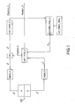
- a trajectory estimation system comprises an EC sensor assembly provided with an accelerometer A with at least one measuring axis and a gyrometer G with at least one measuring axis integrally linked.
- the system comprises a retroactivation module CORR_POS_A of an angular position Position_A of the gyrometer G among a plurality of successive instants, corresponding to the sampling instants on a time interval, from the Cartesian positions Position_C of the accelerometer A to at least two of said successive instants and predetermined information INF _PRED_TRAJ representative of the trajectory of the accelerometer A during the time interval [ t 1 ; t 2 ] by a rotation, which, applied to the trajectory, allows it to better check said predetermined information, ie to minimize a difference between said predetermined information INF_PRED_TRAJ and their equivalent on the trajectory obtained after rotation.
- a model of rotary registration of the trajectory obtained using the measurements of the accelerometer A so that it corresponds as best as possible to the predetermined information (ie the prior knowledge expressed in the form of parameters predetermined) of this trajectory) is inverted to find the rotation parameters of this rotary registration, these rotation parameters being then used to correct the angular position Position_A above.
- the time interval is delimited by a first terminal t 1 and a second terminal later t 2 .
- Samples over the time interval [ t 1 ; t 2 ] are indexed t l so that l varies between 1 and N, and t 1 is t 1 , and t N is t 2 .
- We define the trajectory as the set of Cartesian positions Position_C successive.
- the terminals t 1 and t 2 may correspond to two successive instants of zero velocity of one foot delimiting a phase between two instants of zero velocity of a foot or "MidStance" in English language.
- the system further comprises a memory module MEM_A of first measurements a b delivered by the accelerometer A, and a memory module MEM_G of second measurements ⁇ b delivered by the gyrometer G to said plurality of successive instants of said interval of time, in a movable reference BF linked to the EC sensor assembly.
- a first determination module DET_POS_A determines the angular position Position_A of the gyrometer G defined by angles or a quaternion representing the rotation making it possible to go from the NF mark to the BF mark successive instant audits t 1 , t 2 , ... t N-1 t N , from the second measurements ⁇ b .
- a second determination module DET_POS_C determines the Cartesian position Position_C of the accelerometer A, in the fixed overall reference NF, at said successive instants t 1 , t 2 , ... t N-1 , t N , from the first measurements a b and the angular position Position_A provided by the first determination module DET_POS_A, after a reference change made by a reference change module CR to go from the local reference BF to the NF mark (because after iterations, NF 'tends to confuse with NF, as described later in the description).
- the retroactive correction module CORR_POS_A is adapted to iteratively correct the angular position Position_A.
- the correction can be applied either at angular velocities (ie before an integration of the measurements of the gyrometer G, or applied at angles (ie after an integration of the measurements of the gyrometer G)
- the retroactive correction module CORR_POS_A is, furthermore, adapted to correct the Cartesian position Position_C to at least one of said successive instants t 1 , t 2 , ... t N-1 , t N.
- the predetermined information INF_PRED_TRAJ may comprise a substantially planar trajectory information of the accelerometer between a first instant and a second different instant, among said successive instants t 1 , t 2 , ... t N-1 , t N of said time interval [ t 1 ; t 2 ].
- the orientation of the plane around which the points of the trajectory are located can be known relative to the vertical or to the north.
- the path between said first and second instants may comprise a known heading and / or a known slope.
- the first and second instants may be the limits of the time interval.
- the predetermined information INF_PRED_TRAJ can include possible Cartesian positions stored, that is to say the Cartesian coordinates of points considered a priori as being part of the trajectory.
- the system can be adapted to be attached to a user, a mobile terminal, or a land, air or sea vehicle.
- a mobile terminal or a land, air or sea vehicle.
- fastening means near a user's ankle.
- An originality of the present invention comes from the fact that from knowledge on the trajectory (the trajectory is defined by the set of Cartesian positions between two given instants), the rotation is determined which, by turning the trajectory, makes it possible to satisfy the knowledge on the trajectory, to come correct the orientation or angular position Position_A by making use of this rotation then to recalculate the trajectory.
- correction is applied on a given time window.
- correction approach can be iterative.
- This correction Pos_A_C is distributed, in a predetermined way to define, for example linearly, by a division equirepart of the correction by dividing by the number of samples N, on attitudes or positions Position_A angular positions determined from the gyro measurements. Then the trajectory is recalculated.
- IMUs inertial measurement units
- the EC sensor assembly is attached to the movable body.
- the measurement of the instantaneous rotation vector is a necessity because of changes in attitude or angular position of the EC sensor assembly over time.
- the North reference or fixed global reference, or NF for "North Frame” in English is a fixed reference with respect to the terrestrial reference. It is used throughout the movement (walk or run).
- the North NF mark can be considered as the reference mark: the orientations or angular positions and the positions or positions Cartesian are measured in this reference.
- the fixed global coordinate system NF is defined by its origin O NF and its axes ( x NF , y NF , z NF ).
- the axes refer to the terrestrial landmark by the directions East, North, and High.
- Its origin O NF may be where the movement begins or at any other location.
- the data expressed in this frame are noted with an exponent n.
- the local or sensor-related benchmark or BF for "Body Frame” in English is the repository of the EC sensor assembly in which the raw data is measured. Its center is O BF . The data in this frame are noted with an exponent b. Its axes ( x BF , y BF , z BF ) correspond to the axes of the sensors (in the case of triaxial sensors) at each instant. The coordinates of its origin O BF in the fixed overall reference NF correspond to the location of the sensor in the fixed overall reference NF.
- an intermediate marker or SF for "Step Frame” in English is defined.
- the intermediate marker SF is a reference linked to the Earth, but only during a time interval [ t 1 , t 2 ] (for example during a step).
- This marker is used for movements with less than six degrees of freedom or six DOFs for "Degrees of Freedom” in English. For example, it is used when the sensor assembly EC has an invariant axis of rotation and / or a plane movement during the time interval [ t 1 , t 2 ] .
- the NF mark is a reference close to the NF mark which takes into account the drift due to the integration of the gyrometer. Assuming this zero drift NF and NF 'are merged. Otherwise, the NF 'mark is defined by the axes ( x NF' , y BF , z BF ) and the center O BF .
- the reference NF ' is the reference relative to which are expressed before correction the position_A angular position obtained by integrating the gyro and the cartesian position Position_C estimated double integrating the own acceleration.
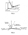
- the figure 3 represents the fixed global NF and local BF benchmarks.
- the local coordinate system BF is linked to the fixed global coordinate system NF by a translation and a rotation.
- all quaternions are, for example, unit quaternions.
- the accelerometer measures the sum of the accelerations applied to the sensor.
- the accelerometer measures, in addition to Earth's gravity, the proper acceleration experienced by the sensor.
- the proper acceleration at p is defined as the external acceleration experienced by the sensor, which is equal to the time derivative of the sensor speed.
- the gyro provides measurements for determining a quaternion of orientation.
- q bn ( t ) [ q bn , 0 ( t ) q bn, 1 ( t ) q bn, 2 ( t ) q bn , 3 ( t )] T the time-varying quaternion describing the orientation of the benchmark local BF relative to the fixed global reference NF.
- the first determination module DET_POS_A of the angular position Position_A of the gyrometer G integrates the differential equation (6) from q bn (0), where q bn (0) . corresponds to the initial orientation.
- equation (6) (or its discretized version) leads to a corrupt estimate of the attitude quaternion, and thus of the attitude or angular position.
- the orientation drift is generally expressed as an erroneous orientation of the local coordinate system BF. Since the main orientation problem is to make a reference change to express the acceleration data of the local coordinate system BF to the fixed global coordinate system NF, it is considered that an erroneous quaternion q nb does not allow a reference change of the local coordinate system. BF at the NF fixed global coordinate system, but at the NF 'mark having drifted, ie turned progressively. Consequently, NF 'is defined as a reference deviated from the fixed overall reference NF; it is described by its orientation relative to the fixed overall reference NF given by the quaternion q n'n .
- Is t 1 ⁇ t 2 the time interval of the SW phase of movement or flight of the foot (foot in the air) of the stride of the detection step number ⁇ (corresponding to the number ⁇ step ). It is assumed that q n'n ( t ) is invariant in time during each flight phase SW for t ⁇ t 1 ⁇ t 2 ⁇ .
- Another problem is the drift of the position because of the double temporal integration of the acceleration measurements.
- the acceleration is integrated only during the flight phase SW, while during the remaining time, the speed is set to zero.
- step detection methods it is possible to determine whether the foot is moving or not.
- the speed of a pedestrian's ankle is calculated step by step, while the orientation is determined continuously at the index of time I with the quaternion q bn' l
- This step is performed by the CR index change module.
- the main problem is that the vertical direction of the NF mark is different from that of the fixed overall mark NF.
- the acceleration is integrated twice, separately for each step, in order to calculate, after all, the complete trajectory of the ankle.
- v I not t v I not t 1 ⁇ + ⁇ t 1 ⁇ t ⁇ at p not t d t
- the calculated position may still be subject to drift because of qn ( t ).
- trajectory of the ankle is included in a plane (plane movement). Assuming that the plane of the trajectory of the true step (plane of the march) is vertical, then any orientation drift would incline the vertical plane.
- the figure 4 illustrates the case of a trajectory drift (for a step) and the corresponding trajectory that we suppose to be the "real trajectory” or "true".
- the quaternion q ⁇ vs corrects the trajectory of the step. It is thus strictly speaking the application of a model of rotary registration of the trajectory as calculated during the steps corresponding to the relations (14) to (17) under the constraint of a priori knowledge on this trajectory constituted by the hypotheses preceding.
- the orientation drift can be represented by the rotation matrix R c or equivalently, with the quaternion q ⁇ vs .
- the rotation matrix R c or equivalently, with the quaternion q ⁇ vs .
- the calculated trajectory can be rotated so as to have a predefined inclination displacement, for example horizontal.
- a predefined inclination displacement for example horizontal.
- qn ( t ) is invariant in time for short durations, more precisely during the flight phase of each step.
- An object of the invention is to calculate the corrected orientation q bn + l by applying a correction q l
- the ⁇ ⁇ vs linearly varying over time at the calculated orientation (in this case the correction increases linearly over time), so as to compensate for the drift of q bn' l by applying the following relation: q b not + l q b not ' l ⁇ q - l
- the ⁇ ⁇ vs for l ⁇ l 2 ⁇ - 1 : l 2 ⁇ in which : q b not ' l q - ⁇ b l ⁇ ...
- The q ⁇ vs ⁇ q bn' The , which is equivalent to q bn +
- The q bn' The ⁇ q - ⁇ vs .
- the trajectory is recalculated from the corrected orientation q bn + .
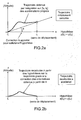
- the Figures 7a, 7b, and 7c represent the three-dimensional or 3D trajectory of the pedestrian's ankle.
- the correction is made with the first assumption of constant angle between NF and NF '(by equation (24) and the previous ones) and on the Figure 7c , the correction is made with the second hypothesis of linear variation of the angle between NF and NF '.
- the proposed corrections guarantee the constraints, as illustrated by the Figures 7b and 7c .
- Figures 8a and 8b respectively show the same trajectories as those of Figures 6b and 6c in the horizontal plane. In this case, the directions of displacement with respect to North ⁇ b and ⁇ b are biased, but we can notice on that the correction of orientation with the second hypothesis clearly reduces this drift .
Landscapes
- Engineering & Computer Science (AREA)
- Radar, Positioning & Navigation (AREA)
- Remote Sensing (AREA)
- Physics & Mathematics (AREA)
- General Physics & Mathematics (AREA)
- Automation & Control Theory (AREA)
- Navigation (AREA)
- Instructional Devices (AREA)
Claims (13)
- Verfahren zur Schätzung eines Wegs eines mobilen Elements oder Körpers mit Hilfe einer Sensoreinheit, wobei diese Sensoreinheit an dem mobilen Element oder Körper befestigt ist und einen Beschleunigungsmesser und ein Gyroskop, die fest verbunden sind, umfasst, das die folgenden Schritte umfasst:- Empfang von Beschleunigungswerten, die von dem Beschleunigungsmesser geliefert werden, die in mindestens zwei Augenblicken aus einer Mehrzahl aufeinanderfolgender Augenblicke eines Zeitintervalls gemessen werden,- Empfang von Winkelgeschwindigkeitswerten, die von dem Gyroskop geliefert werden, die in mindestens zwei Augenblicken aus der Mehrzahl aufeinanderfolgender Augenblicke dieses Zeitintervalls gemessen werden,- Verarbeitung der gemessenen Werte zur Schätzung, einerseits, von mindestens einem Winkelpositionswert mit Hilfe der Winkelgeschwindigkeitswerte und, andererseits, von mindestens zwei kartesischen Positionswerten, die einen Weg des mobilen Elements oder Körpers mit Hilfe der Beschleunigungswerte und dem mindestens einen Winkelpositionswert, der zuvor geschätzt wurde, definieren,dadurch gekennzeichnet, dass es außerdem die folgenden Schritte umfasst:- Schätzung von Rotationsparametern durch Umkehren eines Rotations-Neueinstellmodells des geschätzten Wegs, unter der Auflage einer Apriorikenntnis des Wegs, wobei diese Apriorikenntnis aus vorbestimmten Parametern dieses Wegs gebildet ist, und- retroaktive Korrektur des mindestens einen geschätzten Winkelpositionswerts durch Anwenden einer Drehung auf diesen Wert mit Hilfe der geschätzten Rotationsparameter derart, dass mindestens ein korrigierter Winkelpositionswert geliefert wird.
- Schätzungsverfahren eines Wegs nach Anspruch 1, wobei der retroaktive Korrekturschritt außerdem eine retroaktive Korrektur der kartesischen Positionswerte mit Hilfe der Beschleunigungswerte und des mindestens einen korrigierten Winkelpositionswerts umfasst.
- Schätzungsverfahren eines Wegs nach Anspruch 1 oder 2, wobei:- die von dem Beschleunigungsmesser gelieferten Beschleunigungswerte und die von dem Gyroskop gelieferten Winkelgeschwindigkeitswerte in einem mobilen Bezugssystem, das mit der Sensoreinheit verbunden ist, ausgedrückt sind, und- bei dem Verarbeitungsschritt der gelieferten Werte, die Schätzung des mindestens einen Winkelpositionswerts in der Form von Rotationswinkelparametern in Bezug auf Achsen eines globalen stationären Bezugssystems, das mit dem terrestrischen Bezugssystem verbunden ist, ausgedrückt wird, und die Schätzung der kartesischen Positionswerte in der Form kartesischer Koordinaten in demselben globalen stationären Bezugssystem ausgedrückt wird.
- Schätzungsverfahren eines Wegs nach einem der Ansprüche 1 bis 3, wobei der retroaktive Korrekturschritt in mehreren Iterationen für eine iterative Korrektur des mindestens einen geschätzten Winkelpositionswerts ausgeführt wird.
- Schätzungsverfahren eines Wegs nach einem der Ansprüche 1 bis 4, wobei die Rotationsparameter diejenigen eines Quaternion sind.
- Schätzungsverfahren eines Wegs nach einem der Ansprüche 1 bis 5, wobei die Apriorikenntnis des Wegs Winkelausrichtungsparameter insbesondere bezüglich der Senkrechten oder des Nordens eines Plans umfasst, der als den Weg enthalten müssend betrachtet wird.
- Schätzungsverfahren eines Wegs nach einem der Ansprüche 1 bis 6, wobei die Apriorikenntnis des Wegs die kartesischen Koordinaten von mindestens zwei Punkten, die als zu dem Weg gehören müssend betrachtet werden.
- Schätzungsverfahren eines Wegs nach einem der Ansprüche 1 bis 7, wobei die Apriorikenntnis des Wegs Kurs- oder Neigungsparameter des Wegs umfasst.
- Schätzungsverfahren eines Wegs nach einem der Ansprüche 1 bis 8, wobei der retroaktive Korrekturschritt so konzipiert ist, dass die mit Hilfe der geschätzten Rotationsparameter ausgeführte Korrektur vorbestimmt auf einem Teil oder allen der gesamten Vielzahl aufeinanderfolgender Augenblicke verteilt wird.
- Schätzungsverfahren eines Wegs nach Anspruch 9, wobei die vorbestimmte Verteilung der retroaktiven Korrektur derart definiert ist, dass die mit Hilfe der geschätzten Rotationsparameter berechneten Korrekturparameter auf einem Teil oder allen der gesamten Vielzahl aufeinanderfolgender Augenblicke linear steigen.
- Computerprogramm, das von einem Kommunikationsnetzwerk ausgehend heruntergeladen und/oder auf einem von einem Computer lesbaren Träger aufgezeichnet werden kann und/oder von einem Prozessor ausführbar ist, dadurch gekennzeichnet, dass es Anweisungen für die Ausführung der Schritte eines Schätzungsverfahrens eines Wegs nach einem der Ansprüche 1 bis 10 umfasst, wenn das Programm auf einem Computer ausgeführt wird.
- Schätzungssystem eines Wegs eines mobilen Elements oder Körpers, das umfasst:- einen Beschleunigungsmesser, der geeignet ist, Beschleunigungswerte zu liefern, die in aufeinanderfolgenden Augenblicken eines gegebenen Zeitintervalls gemessen werden,- ein Gyroskop, das fest mit dem Beschleunigungsmesser verbunden ist, das geeignet ist, Winkelgeschwindigkeitswerte zu liefern, die in aufeinanderfolgenden Augenblicken dieses Zeitintervalls gemessen werden, und- Verarbeitungsmittel der von dem Beschleunigungsmesser und dem Gyroskop gelieferten Werte, die zur Umsetzung eines Schätzungsverfahrens eines Wegs nach einem der Ansprüche 1 bis 10 konzipiert sind.
- Schätzungssystem eines Wegs nach Anspruch 12, das Mittel zum festen Befestigen des Beschleunigungsmessers und/oder des Gyroskops an einem Benutzer, zum Beispiel an dem Knöchel dieses Benutzers, an einem mobilen Endgerät oder an einem Land-, Luft- oder Seefahrzeug umfasst.
Applications Claiming Priority (3)
| Application Number | Priority Date | Filing Date | Title |
|---|---|---|---|
| FR1059966A FR2968395B1 (fr) | 2010-12-01 | 2010-12-01 | Systeme d'estimation d'une trajectoire |
| FR1059965 | 2010-12-01 | ||
| PCT/FR2011/052840 WO2012072957A1 (fr) | 2010-12-01 | 2011-12-01 | Procede et systeme d'estimation d'une trajectoire d'un element ou corps mobile |
Publications (2)
| Publication Number | Publication Date |
|---|---|
| EP2646775A1 EP2646775A1 (de) | 2013-10-09 |
| EP2646775B1 true EP2646775B1 (de) | 2015-10-14 |
Family
ID=45446071
Family Applications (1)
| Application Number | Title | Priority Date | Filing Date |
|---|---|---|---|
| EP11805078.0A Active EP2646775B1 (de) | 2010-12-01 | 2011-12-01 | Verfahren und system zur schätzung des weges eines mobilen elements oder körpers |
Country Status (6)
| Country | Link |
|---|---|
| US (1) | US10352959B2 (de) |
| EP (1) | EP2646775B1 (de) |
| JP (1) | JP6015664B2 (de) |
| KR (1) | KR20130127991A (de) |
| CN (1) | CN103314274B (de) |
| WO (1) | WO2012072957A1 (de) |
Families Citing this family (36)
| Publication number | Priority date | Publication date | Assignee | Title |
|---|---|---|---|---|
| US9395190B1 (en) | 2007-05-31 | 2016-07-19 | Trx Systems, Inc. | Crowd sourced mapping with robust structural features |
| WO2013188598A2 (en) | 2012-06-12 | 2013-12-19 | Trx Systems, Inc. | Fusion of sensor and map data using constraint based optimization |
| US20140236529A1 (en) * | 2013-02-18 | 2014-08-21 | Motorola Mobility Llc | Method and Apparatus for Determining Displacement from Acceleration Data |
| US11268818B2 (en) | 2013-03-14 | 2022-03-08 | Trx Systems, Inc. | Crowd sourced mapping with robust structural features |
| US11156464B2 (en) | 2013-03-14 | 2021-10-26 | Trx Systems, Inc. | Crowd sourced mapping with robust structural features |
| CN103813446B (zh) * | 2014-02-17 | 2017-06-23 | 百度在线网络技术(北京)有限公司 | 一种估算停留区域范围的方法及装置 |
| WO2017184478A1 (en) * | 2016-04-17 | 2017-10-26 | President And Fellows Of Harvard College | Magnetic receptive sensor and optimized drawing and erasing for vertically driving robot |
| WO2015164403A1 (en) * | 2014-04-22 | 2015-10-29 | Blast Motion, Inc. | Initializing an inertial sensor using soft constraints and penalty functions |
| US10518879B1 (en) * | 2014-07-10 | 2019-12-31 | Hrl Laboratories, Llc | System and method for drift-free global trajectory estimation of a mobile platform |
| CN104197975B (zh) * | 2014-08-13 | 2016-06-01 | 电子科技大学 | 一种基于测量值微分约束的传感器测量精度提高方法 |
| EP3180675B1 (de) | 2014-08-16 | 2021-05-26 | Google LLC | Identifizierung von gesten anhand von bewegungsdaten |
| GB201500411D0 (en) * | 2014-09-15 | 2015-02-25 | Isis Innovation | Determining the position of a mobile device in a geographical area |
| TWI525304B (zh) * | 2014-11-26 | 2016-03-11 | 財團法人資訊工業策進會 | 行人導航系統以及方法 |
| US9759561B2 (en) | 2015-01-06 | 2017-09-12 | Trx Systems, Inc. | Heading constraints in a particle filter |
| KR102280780B1 (ko) * | 2015-03-06 | 2021-07-22 | 삼성전자주식회사 | 모션 센서의 측정 정확도를 향상시키기 위한 전자 장치 및 그 방법 |
| US9846040B2 (en) * | 2015-05-08 | 2017-12-19 | Sharp Laboratories Of America, Inc. | System and method for determining the orientation of an inertial measurement unit (IMU) |
| US9844481B2 (en) * | 2015-07-13 | 2017-12-19 | Panasonic Intellectual Property Management Co., Ltd. | Standing/sitting motion assist system, standing/sitting motion assist method, standing/sitting motion assist robot, and non-transitory computer-readable recording medium |
| JP6352877B2 (ja) * | 2015-09-18 | 2018-07-04 | ヤフー株式会社 | マップ生成装置、マップ生成方法及びマップ生成プログラム |
| US20180236352A1 (en) * | 2015-12-04 | 2018-08-23 | Uti Limited Partnership | Wearable inertial electronic device |
| US10156907B2 (en) * | 2015-12-14 | 2018-12-18 | Invensense, Inc. | Device for analyzing the movement of a moving element and associated method |
| WO2017104646A1 (ja) * | 2015-12-18 | 2017-06-22 | 株式会社リコー | 情報処理システム、情報処理装置、情報処理方法、プログラム、および記録媒体 |
| EP3211370A1 (de) * | 2016-02-29 | 2017-08-30 | Movea | Filterverfahren für signale, die von einer sensoreinheit ausgehen, die mindestens einen messfühler eines vektoriellen physikalischen feldes umfasst, das im wesentlichen in bezug auf zeit und raum in einem referenzrahmen konstant ist |
| CN105865452B (zh) * | 2016-04-29 | 2018-10-02 | 浙江国自机器人技术有限公司 | 一种基于间接卡尔曼滤波的移动平台位姿估计方法 |
| FR3051952B1 (fr) * | 2016-05-24 | 2019-06-14 | Thales | Procede et dispositif de localisation d'objets ou de personnes mobiles |
| CN107255795B (zh) * | 2017-06-13 | 2020-01-07 | 山东大学 | 基于ekf/efir混合滤波的室内移动机器人定位方法和装置 |
| CN113218395B (zh) * | 2017-06-23 | 2024-06-11 | 北京方位捷讯科技有限公司 | 行人步行轨迹检测方法、装置及系统 |
| JP7162063B2 (ja) * | 2017-12-29 | 2022-10-27 | フラウンホーファー-ゲゼルシャフト・ツール・フェルデルング・デル・アンゲヴァンテン・フォルシュング・アインゲトラーゲネル・フェライン | オブジェクトの動きを予測する方法、運動モデルを調整する方法、所定量を導出する方法、及び仮想現実ビューを生成する方法 |
| ES2969876T3 (es) * | 2019-01-18 | 2024-05-23 | Szipka Karoly | Sistema de medición, y un procedimiento en relación con el sistema de medición |
| CN111256695B (zh) * | 2020-01-14 | 2022-09-09 | 电子科技大学 | 基于粒子滤波算法的uwb/ins组合室内定位方法 |
| EP4018928A1 (de) * | 2020-12-23 | 2022-06-29 | Feetme | Schuhwerk und verfahren zur schätzung der fussgeschwindigkeit |
| CN113074739B (zh) * | 2021-04-09 | 2022-09-02 | 重庆邮电大学 | 基于动态鲁棒容积卡尔曼的uwb/ins融合定位方法 |
| KR102537028B1 (ko) * | 2021-06-11 | 2023-05-30 | 국방과학연구소 | 비행체의 캐롯 추종(Carrot Chasing) 유도 제어 방법, 캐롯 추종(Carrot Chasing) 유도 제어 장치 및 그 유도 제어 장치를 탑재한 비행체 |
| US12517260B2 (en) | 2021-08-24 | 2026-01-06 | Trx Systems, Inc. | Systems and methods for redundant integrity monitoring |
| JP2023066278A (ja) * | 2021-10-28 | 2023-05-15 | 株式会社ビットキー | 回転検出装置、方法及びプログラム |
| CN114808754A (zh) * | 2022-05-18 | 2022-07-29 | 中铁二十四局集团有限公司 | 一种大型转体桥梁空间位置高精度实时预测方法 |
| KR20250007212A (ko) | 2023-07-05 | 2025-01-14 | 윤우람 | 지중탐사장비용 방위각 측정장치 및 이를 이용한 지중관로 위치정보 획득방법 |
Family Cites Families (17)
| Publication number | Priority date | Publication date | Assignee | Title |
|---|---|---|---|---|
| AU3888699A (en) * | 1998-05-07 | 1999-11-23 | University Of South Florida | Bone marrow cells as a source of neurons for brain and spinal cord repair |
| US6323807B1 (en) | 2000-02-17 | 2001-11-27 | Mitsubishi Electric Research Laboratories, Inc. | Indoor navigation with wearable passive sensors |
| US6609052B2 (en) * | 2001-03-16 | 2003-08-19 | Visteon Global Technologies, Inc. | Torque sensor backup in a steer-by-wire system |
| EP1488197A1 (de) | 2002-03-20 | 2004-12-22 | Visuaide Inc. | Drahtloses in der hand gehaltenes navigationssystem für sehbehinderte fussgänger |
| US7409290B2 (en) * | 2004-04-17 | 2008-08-05 | American Gnc Corporation | Positioning and navigation method and system thereof |
| US20070018890A1 (en) * | 2005-07-22 | 2007-01-25 | Kulyukin Vladimir A | Multi-sensor wayfinding device |
| EP1930693B1 (de) * | 2005-09-30 | 2013-02-13 | Pioneer Corporation | Einrichtung, verfahren und programm zur positionsschätzung und computerlesbares aufzeichnungsmedium |
| JP2007163297A (ja) * | 2005-12-14 | 2007-06-28 | Hitachi Ltd | 測位端末 |
| FR2895500B1 (fr) * | 2005-12-23 | 2008-03-28 | Commissariat Energie Atomique | Procede d'estimation d'un mouvement d'un solide. |
| US7860676B2 (en) * | 2007-06-28 | 2010-12-28 | Hillcrest Laboratories, Inc. | Real-time dynamic tracking of bias |
| US8797214B2 (en) * | 2007-07-06 | 2014-08-05 | Qualcomm Incorporated | Tracking implementing geopositioning and local modes |
| FR2918745B1 (fr) | 2007-07-12 | 2009-09-18 | Commissariat Energie Atomique | Dispositif d'assistance a la navigation d'une personne |
| JP2009156721A (ja) * | 2007-12-27 | 2009-07-16 | Hitachi Ltd | 物体の位置検知方法及びその装置 |
| JP5142801B2 (ja) * | 2008-04-22 | 2013-02-13 | アルパイン株式会社 | オフセット補正装置およびオフセット補正方法 |
| JP2009276094A (ja) * | 2008-05-12 | 2009-11-26 | Sumitomo Electric Ind Ltd | 姿勢特定装置、移動方位特定装置、位置特定装置、コンピュータプログラム及び姿勢特定方法 |
| CN101750060A (zh) * | 2008-12-22 | 2010-06-23 | 财团法人工业技术研究院 | 利用感测元件的定位与检测的系统与方法 |
| TWI407102B (zh) * | 2010-01-26 | 2013-09-01 | Prolific Technology Inc | 三維空間運動感測方法 |
-
2011
- 2011-12-01 KR KR1020137017216A patent/KR20130127991A/ko not_active Withdrawn
- 2011-12-01 WO PCT/FR2011/052840 patent/WO2012072957A1/fr not_active Ceased
- 2011-12-01 JP JP2013541411A patent/JP6015664B2/ja not_active Expired - Fee Related
- 2011-12-01 EP EP11805078.0A patent/EP2646775B1/de active Active
- 2011-12-01 CN CN201180065180.6A patent/CN103314274B/zh not_active Expired - Fee Related
- 2011-12-01 US US13/991,018 patent/US10352959B2/en active Active
Also Published As
| Publication number | Publication date |
|---|---|
| US10352959B2 (en) | 2019-07-16 |
| WO2012072957A1 (fr) | 2012-06-07 |
| KR20130127991A (ko) | 2013-11-25 |
| JP2014506318A (ja) | 2014-03-13 |
| JP6015664B2 (ja) | 2016-10-26 |
| CN103314274A (zh) | 2013-09-18 |
| CN103314274B (zh) | 2016-05-11 |
| EP2646775A1 (de) | 2013-10-09 |
| US20130338961A1 (en) | 2013-12-19 |
Similar Documents
| Publication | Publication Date | Title |
|---|---|---|
| EP2646775B1 (de) | Verfahren und system zur schätzung des weges eines mobilen elements oder körpers | |
| EP2646776B1 (de) | Verfahren und system zur bestimmung der werte der charakteristischen parameter einer bewegung von mindestens zwei gliedmassen einer einheit in form einer gelenkigen leitung | |
| EP3359915B1 (de) | Verfahren zur schätzung der bewegung eines fussgängers | |
| FR3012597B1 (fr) | Procede de localisation en interieur et exterieur et dispositif portatif mettant en œuvre un tel procede | |
| EP2434256B1 (de) | Kamera- und Trägheitsmessgeräteintegration mit Navigationsdatenrückmeldung zur Funktionsverfolgung | |
| EP2350565B1 (de) | Einrichtung und verfahren zum bestimmen eines charakteristikums eines durch aufeinanderfolgende positionen eines starr mit einem mobilen element verbundenen triaxialbeschleunigungsmessers gebildeten pfads | |
| EP2428934B1 (de) | Verfahren zur Schätzung der Bewegung eines Trägers im Verhältnis zu einer Umgebung, und Berechnungsvorrichtung für ein Navigationssystem | |
| US10757333B2 (en) | Method for determining bias in an inertial measurement unit of an image acquisition device | |
| WO2014090878A1 (fr) | Procede de geo localisation precise d'un capteur d'images embarque a bord d'un aeronef | |
| EP3447654B1 (de) | Bestimmungsverfahren der bewegungsbahn eines beweglichen objekts, programm und vorrichtung zur umsetzung dieses verfahrens | |
| CN115127554B (zh) | 一种基于多源视觉辅助的无人机自主导航方法与系统 | |
| WO2018085689A1 (en) | Camera-based heading-hold navigation | |
| EP3227860A1 (de) | Verfahren zur schätzung der bewegung eines trägers in bezug auf eine umgebung und berechnungsvorrichtung für navigationssystem | |
| Benzerrouk et al. | Mems imu/zupt based cubature kalman filter applied to pedestrian navigation system | |
| FR2968395A1 (fr) | Systeme d'estimation d'une trajectoire | |
| CN114279439A (zh) | 一种惯导数据的修正方法、装置和系统 | |
| Andrés López et al. | VCIT-Visually Corrected inertial Tracking | |
| CN117804442A (zh) | 飞行器的位姿确定方法、装置、电子设备及存储介质 | |
| CN119546924A (zh) | 用于借助于相对定位系统校正航位推算导航系统提供的姿态的方法 | |
| WO2015086587A1 (fr) | Procédé et dispositif d'alignement d'une centrale inertielle | |
| CN116026319A (zh) | 融合定位方法、装置、处理器、存储介质及电子装置 | |
| Hun et al. | An Experimental Study of UAV Motion Sensing using GPS Aided MEMS Inertial Sensor |
Legal Events
| Date | Code | Title | Description |
|---|---|---|---|
| PUAI | Public reference made under article 153(3) epc to a published international application that has entered the european phase |
Free format text: ORIGINAL CODE: 0009012 |
|
| 17P | Request for examination filed |
Effective date: 20130531 |
|
| AK | Designated contracting states |
Kind code of ref document: A1 Designated state(s): AL AT BE BG CH CY CZ DE DK EE ES FI FR GB GR HR HU IE IS IT LI LT LU LV MC MK MT NL NO PL PT RO RS SE SI SK SM TR |
|
| DAX | Request for extension of the european patent (deleted) | ||
| GRAP | Despatch of communication of intention to grant a patent |
Free format text: ORIGINAL CODE: EPIDOSNIGR1 |
|
| INTG | Intention to grant announced |
Effective date: 20150512 |
|
| GRAS | Grant fee paid |
Free format text: ORIGINAL CODE: EPIDOSNIGR3 |
|
| GRAA | (expected) grant |
Free format text: ORIGINAL CODE: 0009210 |
|
| AK | Designated contracting states |
Kind code of ref document: B1 Designated state(s): AL AT BE BG CH CY CZ DE DK EE ES FI FR GB GR HR HU IE IS IT LI LT LU LV MC MK MT NL NO PL PT RO RS SE SI SK SM TR |
|
| REG | Reference to a national code |
Ref country code: GB Ref legal event code: FG4D Free format text: NOT ENGLISH |
|
| REG | Reference to a national code |
Ref country code: AT Ref legal event code: REF Ref document number: 755478 Country of ref document: AT Kind code of ref document: T Effective date: 20151015 Ref country code: CH Ref legal event code: EP |
|
| REG | Reference to a national code |
Ref country code: IE Ref legal event code: FG4D Free format text: LANGUAGE OF EP DOCUMENT: FRENCH |
|
| REG | Reference to a national code |
Ref country code: DE Ref legal event code: R096 Ref document number: 602011020666 Country of ref document: DE |
|
| REG | Reference to a national code |
Ref country code: FR Ref legal event code: PLFP Year of fee payment: 5 |
|
| REG | Reference to a national code |
Ref country code: NL Ref legal event code: MP Effective date: 20151014 |
|
| REG | Reference to a national code |
Ref country code: LT Ref legal event code: MG4D |
|
| REG | Reference to a national code |
Ref country code: AT Ref legal event code: MK05 Ref document number: 755478 Country of ref document: AT Kind code of ref document: T Effective date: 20151014 |
|
| PG25 | Lapsed in a contracting state [announced via postgrant information from national office to epo] |
Ref country code: HR Free format text: LAPSE BECAUSE OF FAILURE TO SUBMIT A TRANSLATION OF THE DESCRIPTION OR TO PAY THE FEE WITHIN THE PRESCRIBED TIME-LIMIT Effective date: 20151014 Ref country code: ES Free format text: LAPSE BECAUSE OF FAILURE TO SUBMIT A TRANSLATION OF THE DESCRIPTION OR TO PAY THE FEE WITHIN THE PRESCRIBED TIME-LIMIT Effective date: 20151014 Ref country code: NO Free format text: LAPSE BECAUSE OF FAILURE TO SUBMIT A TRANSLATION OF THE DESCRIPTION OR TO PAY THE FEE WITHIN THE PRESCRIBED TIME-LIMIT Effective date: 20160114 Ref country code: NL Free format text: LAPSE BECAUSE OF FAILURE TO SUBMIT A TRANSLATION OF THE DESCRIPTION OR TO PAY THE FEE WITHIN THE PRESCRIBED TIME-LIMIT Effective date: 20151014 Ref country code: IS Free format text: LAPSE BECAUSE OF FAILURE TO SUBMIT A TRANSLATION OF THE DESCRIPTION OR TO PAY THE FEE WITHIN THE PRESCRIBED TIME-LIMIT Effective date: 20160214 Ref country code: IT Free format text: LAPSE BECAUSE OF FAILURE TO SUBMIT A TRANSLATION OF THE DESCRIPTION OR TO PAY THE FEE WITHIN THE PRESCRIBED TIME-LIMIT Effective date: 20151014 Ref country code: LT Free format text: LAPSE BECAUSE OF FAILURE TO SUBMIT A TRANSLATION OF THE DESCRIPTION OR TO PAY THE FEE WITHIN THE PRESCRIBED TIME-LIMIT Effective date: 20151014 |
|
| PG25 | Lapsed in a contracting state [announced via postgrant information from national office to epo] |
Ref country code: LV Free format text: LAPSE BECAUSE OF FAILURE TO SUBMIT A TRANSLATION OF THE DESCRIPTION OR TO PAY THE FEE WITHIN THE PRESCRIBED TIME-LIMIT Effective date: 20151014 Ref country code: FI Free format text: LAPSE BECAUSE OF FAILURE TO SUBMIT A TRANSLATION OF THE DESCRIPTION OR TO PAY THE FEE WITHIN THE PRESCRIBED TIME-LIMIT Effective date: 20151014 Ref country code: PL Free format text: LAPSE BECAUSE OF FAILURE TO SUBMIT A TRANSLATION OF THE DESCRIPTION OR TO PAY THE FEE WITHIN THE PRESCRIBED TIME-LIMIT Effective date: 20151014 Ref country code: AT Free format text: LAPSE BECAUSE OF FAILURE TO SUBMIT A TRANSLATION OF THE DESCRIPTION OR TO PAY THE FEE WITHIN THE PRESCRIBED TIME-LIMIT Effective date: 20151014 Ref country code: GR Free format text: LAPSE BECAUSE OF FAILURE TO SUBMIT A TRANSLATION OF THE DESCRIPTION OR TO PAY THE FEE WITHIN THE PRESCRIBED TIME-LIMIT Effective date: 20160115 Ref country code: SE Free format text: LAPSE BECAUSE OF FAILURE TO SUBMIT A TRANSLATION OF THE DESCRIPTION OR TO PAY THE FEE WITHIN THE PRESCRIBED TIME-LIMIT Effective date: 20151014 Ref country code: BE Free format text: LAPSE BECAUSE OF NON-PAYMENT OF DUE FEES Effective date: 20151231 Ref country code: RS Free format text: LAPSE BECAUSE OF FAILURE TO SUBMIT A TRANSLATION OF THE DESCRIPTION OR TO PAY THE FEE WITHIN THE PRESCRIBED TIME-LIMIT Effective date: 20151014 Ref country code: PT Free format text: LAPSE BECAUSE OF FAILURE TO SUBMIT A TRANSLATION OF THE DESCRIPTION OR TO PAY THE FEE WITHIN THE PRESCRIBED TIME-LIMIT Effective date: 20160215 |
|
| REG | Reference to a national code |
Ref country code: DE Ref legal event code: R097 Ref document number: 602011020666 Country of ref document: DE |
|
| PG25 | Lapsed in a contracting state [announced via postgrant information from national office to epo] |
Ref country code: CZ Free format text: LAPSE BECAUSE OF FAILURE TO SUBMIT A TRANSLATION OF THE DESCRIPTION OR TO PAY THE FEE WITHIN THE PRESCRIBED TIME-LIMIT Effective date: 20151014 Ref country code: LU Free format text: LAPSE BECAUSE OF FAILURE TO SUBMIT A TRANSLATION OF THE DESCRIPTION OR TO PAY THE FEE WITHIN THE PRESCRIBED TIME-LIMIT Effective date: 20151201 Ref country code: MC Free format text: LAPSE BECAUSE OF FAILURE TO SUBMIT A TRANSLATION OF THE DESCRIPTION OR TO PAY THE FEE WITHIN THE PRESCRIBED TIME-LIMIT Effective date: 20151014 |
|
| REG | Reference to a national code |
Ref country code: CH Ref legal event code: PL |
|
| PLBE | No opposition filed within time limit |
Free format text: ORIGINAL CODE: 0009261 |
|
| STAA | Information on the status of an ep patent application or granted ep patent |
Free format text: STATUS: NO OPPOSITION FILED WITHIN TIME LIMIT |
|
| PG25 | Lapsed in a contracting state [announced via postgrant information from national office to epo] |
Ref country code: DK Free format text: LAPSE BECAUSE OF FAILURE TO SUBMIT A TRANSLATION OF THE DESCRIPTION OR TO PAY THE FEE WITHIN THE PRESCRIBED TIME-LIMIT Effective date: 20151014 Ref country code: RO Free format text: LAPSE BECAUSE OF FAILURE TO SUBMIT A TRANSLATION OF THE DESCRIPTION OR TO PAY THE FEE WITHIN THE PRESCRIBED TIME-LIMIT Effective date: 20151014 Ref country code: SM Free format text: LAPSE BECAUSE OF FAILURE TO SUBMIT A TRANSLATION OF THE DESCRIPTION OR TO PAY THE FEE WITHIN THE PRESCRIBED TIME-LIMIT Effective date: 20151014 Ref country code: SK Free format text: LAPSE BECAUSE OF FAILURE TO SUBMIT A TRANSLATION OF THE DESCRIPTION OR TO PAY THE FEE WITHIN THE PRESCRIBED TIME-LIMIT Effective date: 20151014 Ref country code: EE Free format text: LAPSE BECAUSE OF FAILURE TO SUBMIT A TRANSLATION OF THE DESCRIPTION OR TO PAY THE FEE WITHIN THE PRESCRIBED TIME-LIMIT Effective date: 20151014 |
|
| 26N | No opposition filed |
Effective date: 20160715 |
|
| REG | Reference to a national code |
Ref country code: IE Ref legal event code: MM4A |
|
| PG25 | Lapsed in a contracting state [announced via postgrant information from national office to epo] |
Ref country code: LI Free format text: LAPSE BECAUSE OF NON-PAYMENT OF DUE FEES Effective date: 20151231 Ref country code: CH Free format text: LAPSE BECAUSE OF NON-PAYMENT OF DUE FEES Effective date: 20151231 Ref country code: IE Free format text: LAPSE BECAUSE OF NON-PAYMENT OF DUE FEES Effective date: 20151201 |
|
| PG25 | Lapsed in a contracting state [announced via postgrant information from national office to epo] |
Ref country code: SI Free format text: LAPSE BECAUSE OF FAILURE TO SUBMIT A TRANSLATION OF THE DESCRIPTION OR TO PAY THE FEE WITHIN THE PRESCRIBED TIME-LIMIT Effective date: 20151014 |
|
| REG | Reference to a national code |
Ref country code: FR Ref legal event code: PLFP Year of fee payment: 6 |
|
| PG25 | Lapsed in a contracting state [announced via postgrant information from national office to epo] |
Ref country code: BG Free format text: LAPSE BECAUSE OF FAILURE TO SUBMIT A TRANSLATION OF THE DESCRIPTION OR TO PAY THE FEE WITHIN THE PRESCRIBED TIME-LIMIT Effective date: 20151014 Ref country code: HU Free format text: LAPSE BECAUSE OF FAILURE TO SUBMIT A TRANSLATION OF THE DESCRIPTION OR TO PAY THE FEE WITHIN THE PRESCRIBED TIME-LIMIT; INVALID AB INITIO Effective date: 20111201 |
|
| PG25 | Lapsed in a contracting state [announced via postgrant information from national office to epo] |
Ref country code: CY Free format text: LAPSE BECAUSE OF FAILURE TO SUBMIT A TRANSLATION OF THE DESCRIPTION OR TO PAY THE FEE WITHIN THE PRESCRIBED TIME-LIMIT Effective date: 20151014 |
|
| PG25 | Lapsed in a contracting state [announced via postgrant information from national office to epo] |
Ref country code: MT Free format text: LAPSE BECAUSE OF FAILURE TO SUBMIT A TRANSLATION OF THE DESCRIPTION OR TO PAY THE FEE WITHIN THE PRESCRIBED TIME-LIMIT Effective date: 20151014 |
|
| REG | Reference to a national code |
Ref country code: FR Ref legal event code: PLFP Year of fee payment: 7 |
|
| PG25 | Lapsed in a contracting state [announced via postgrant information from national office to epo] |
Ref country code: TR Free format text: LAPSE BECAUSE OF FAILURE TO SUBMIT A TRANSLATION OF THE DESCRIPTION OR TO PAY THE FEE WITHIN THE PRESCRIBED TIME-LIMIT Effective date: 20151014 Ref country code: MK Free format text: LAPSE BECAUSE OF FAILURE TO SUBMIT A TRANSLATION OF THE DESCRIPTION OR TO PAY THE FEE WITHIN THE PRESCRIBED TIME-LIMIT Effective date: 20151014 |
|
| PG25 | Lapsed in a contracting state [announced via postgrant information from national office to epo] |
Ref country code: AL Free format text: LAPSE BECAUSE OF FAILURE TO SUBMIT A TRANSLATION OF THE DESCRIPTION OR TO PAY THE FEE WITHIN THE PRESCRIBED TIME-LIMIT Effective date: 20151014 |
|
| PGFP | Annual fee paid to national office [announced via postgrant information from national office to epo] |
Ref country code: DE Payment date: 20251119 Year of fee payment: 15 |
|
| PGFP | Annual fee paid to national office [announced via postgrant information from national office to epo] |
Ref country code: GB Payment date: 20251113 Year of fee payment: 15 |
|
| PGFP | Annual fee paid to national office [announced via postgrant information from national office to epo] |
Ref country code: FR Payment date: 20251124 Year of fee payment: 15 |