EP2647273B1 - Refroidissement d'éléments électroniques thermogènes - Google Patents
Refroidissement d'éléments électroniques thermogènes Download PDFInfo
- Publication number
- EP2647273B1 EP2647273B1 EP11799544.9A EP11799544A EP2647273B1 EP 2647273 B1 EP2647273 B1 EP 2647273B1 EP 11799544 A EP11799544 A EP 11799544A EP 2647273 B1 EP2647273 B1 EP 2647273B1
- Authority
- EP
- European Patent Office
- Prior art keywords
- heat
- motherboard
- server rack
- brackets
- assembly
- Prior art date
- Legal status (The legal status is an assumption and is not a legal conclusion. Google has not performed a legal analysis and makes no representation as to the accuracy of the status listed.)
- Active
Links
Images



Classifications
-
- H—ELECTRICITY
- H05—ELECTRIC TECHNIQUES NOT OTHERWISE PROVIDED FOR
- H05K—PRINTED CIRCUITS; CASINGS OR CONSTRUCTIONAL DETAILS OF ELECTRIC APPARATUS; MANUFACTURE OF ASSEMBLAGES OF ELECTRICAL COMPONENTS
- H05K7/00—Constructional details common to different types of electric apparatus
- H05K7/20—Modifications to facilitate cooling, ventilating, or heating
- H05K7/20709—Modifications to facilitate cooling, ventilating, or heating for server racks or cabinets; for data centers, e.g. 19-inch computer racks
- H05K7/20718—Forced ventilation of a gaseous coolant
-
- H—ELECTRICITY
- H05—ELECTRIC TECHNIQUES NOT OTHERWISE PROVIDED FOR
- H05K—PRINTED CIRCUITS; CASINGS OR CONSTRUCTIONAL DETAILS OF ELECTRIC APPARATUS; MANUFACTURE OF ASSEMBLAGES OF ELECTRICAL COMPONENTS
- H05K7/00—Constructional details common to different types of electric apparatus
- H05K7/20—Modifications to facilitate cooling, ventilating, or heating
- H05K7/2029—Modifications to facilitate cooling, ventilating, or heating using a liquid coolant with phase change in electronic enclosures
- H05K7/20336—Heat pipes, e.g. wicks or capillary pumps
-
- H—ELECTRICITY
- H05—ELECTRIC TECHNIQUES NOT OTHERWISE PROVIDED FOR
- H05K—PRINTED CIRCUITS; CASINGS OR CONSTRUCTIONAL DETAILS OF ELECTRIC APPARATUS; MANUFACTURE OF ASSEMBLAGES OF ELECTRICAL COMPONENTS
- H05K7/00—Constructional details common to different types of electric apparatus
- H05K7/20—Modifications to facilitate cooling, ventilating, or heating
- H05K7/2039—Modifications to facilitate cooling, ventilating, or heating characterised by the heat transfer by conduction from the heat generating element to a dissipating body
- H05K7/20436—Inner thermal coupling elements in heat dissipating housings, e.g. protrusions or depressions integrally formed in the housing
- H05K7/20445—Inner thermal coupling elements in heat dissipating housings, e.g. protrusions or depressions integrally formed in the housing the coupling element being an additional piece, e.g. thermal standoff
-
- H—ELECTRICITY
- H05—ELECTRIC TECHNIQUES NOT OTHERWISE PROVIDED FOR
- H05K—PRINTED CIRCUITS; CASINGS OR CONSTRUCTIONAL DETAILS OF ELECTRIC APPARATUS; MANUFACTURE OF ASSEMBLAGES OF ELECTRICAL COMPONENTS
- H05K7/00—Constructional details common to different types of electric apparatus
- H05K7/20—Modifications to facilitate cooling, ventilating, or heating
- H05K7/20709—Modifications to facilitate cooling, ventilating, or heating for server racks or cabinets; for data centers, e.g. 19-inch computer racks
- H05K7/20718—Forced ventilation of a gaseous coolant
- H05K7/20727—Forced ventilation of a gaseous coolant within server blades for removing heat from heat source
-
- H—ELECTRICITY
- H05—ELECTRIC TECHNIQUES NOT OTHERWISE PROVIDED FOR
- H05K—PRINTED CIRCUITS; CASINGS OR CONSTRUCTIONAL DETAILS OF ELECTRIC APPARATUS; MANUFACTURE OF ASSEMBLAGES OF ELECTRICAL COMPONENTS
- H05K7/00—Constructional details common to different types of electric apparatus
- H05K7/20—Modifications to facilitate cooling, ventilating, or heating
- H05K7/20709—Modifications to facilitate cooling, ventilating, or heating for server racks or cabinets; for data centers, e.g. 19-inch computer racks
- H05K7/208—Liquid cooling with phase change
- H05K7/20809—Liquid cooling with phase change within server blades for removing heat from heat source
-
- H—ELECTRICITY
- H10—SEMICONDUCTOR DEVICES; ELECTRIC SOLID-STATE DEVICES NOT OTHERWISE PROVIDED FOR
- H10W—GENERIC PACKAGES, INTERCONNECTIONS, CONNECTORS OR OTHER CONSTRUCTIONAL DETAILS OF DEVICES COVERED BY CLASS H10
- H10W40/00—Arrangements for thermal protection or thermal control
- H10W40/70—Fillings or auxiliary members in containers or in encapsulations for thermal protection or control
- H10W40/73—Fillings or auxiliary members in containers or in encapsulations for thermal protection or control for cooling by change of state
-
- H—ELECTRICITY
- H05—ELECTRIC TECHNIQUES NOT OTHERWISE PROVIDED FOR
- H05K—PRINTED CIRCUITS; CASINGS OR CONSTRUCTIONAL DETAILS OF ELECTRIC APPARATUS; MANUFACTURE OF ASSEMBLAGES OF ELECTRICAL COMPONENTS
- H05K7/00—Constructional details common to different types of electric apparatus
- H05K7/20—Modifications to facilitate cooling, ventilating, or heating
- H05K7/20009—Modifications to facilitate cooling, ventilating, or heating using a gaseous coolant in electronic enclosures
- H05K7/20136—Forced ventilation, e.g. by fans
- H05K7/20154—Heat dissipaters coupled to components
- H05K7/20163—Heat dissipaters coupled to components the components being isolated from air flow, e.g. hollow heat sinks, wind tunnels or funnels
-
- H—ELECTRICITY
- H10—SEMICONDUCTOR DEVICES; ELECTRIC SOLID-STATE DEVICES NOT OTHERWISE PROVIDED FOR
- H10W—GENERIC PACKAGES, INTERCONNECTIONS, CONNECTORS OR OTHER CONSTRUCTIONAL DETAILS OF DEVICES COVERED BY CLASS H10
- H10W40/00—Arrangements for thermal protection or thermal control
- H10W40/40—Arrangements for thermal protection or thermal control involving heat exchange by flowing fluids
- H10W40/43—Arrangements for thermal protection or thermal control involving heat exchange by flowing fluids by flowing gases, e.g. forced air cooling
Definitions
- This disclosure relates to systems and methods for providing cooling for electronic equipment and, more particularly, to systems and methods for cooling electronic devices on server racks in computer data centers.
- Power consumption and electronics operation may also generate heat. That is because, by simple laws of physics, all the power has to go somewhere, and that somewhere is, in the end, conversion into heat.
- a pair of microprocessors mounted on a single motherboard can draw hundreds of watts or more of power. Multiply that figure by several thousand (or tens of thousands) to account for the many computers in a large data center, and one can readily appreciate the amount of heat that can be generated.
- the effects of power consumed by the critical load in the data center are often compounded when one incorporates all of the ancillary equipment required to support the critical load.
- the consequence of inadequate and/or insufficient cooling may be the failure of one or more electronic devices on the tray due to a temperature of the device exceeding a maximum rated temperature. While certain redundancies may be built into a computer data center, a server rack, and even individual trays, the failure of devices due to overheating can come at a great cost in terms of speed, efficiency, and expense.
- US 2007/042514 (A1 ) describes a method and apparatus adapted to cool a circuit board in a rack-mountable housing includes transferring heat from a heat source on the board to a primary heat storage medium positioned at an edge of the board or within a rack-mountable housing using at least one heat pipe, transferring heat from the primary heat storage medium to a secondary heat storage medium positioned in the rack-mountable housing through contacting surfaces of the primary and secondary heat storage mediums, transferring heat from the secondary heat storage medium to a heat exchanger, which may be positioned within the rack-mountable housing, using at least one heat pipe, and cooling the heat exchanger.
- a method and apparatus adapted to cool a printed circuit board includes transferring heat from a heat source on the board to a heat exchanger positioned in the rack-mountable housing using at least one heat pipe, and cooling the heat exchanger.
- US 2006/005980 (A1 ) describes a thermal energy management system having a heat spreading device that is operatively engaged with at least one semiconductor chip and a thermal bus operatively engaged with the heat spreading device so as to transport thermal energy from the heat spreading device to a heat sink.
- the heat spreading device includes a heat pipe and the thermal bus includes a loop thermosyphon.
- a second thermal bus may be operatively engaged with the first-thermal bus so as to transport thermal energy from the first thermal bus to a heat sink.
- the second thermal bus may also include a loop thermosyphon.
- a method of managing thermal energy in an electronic system includes spreading thermal energy generated by one or more devices over a surface that is relatively larger than the devices, thermally coupling an evaporator portion of a loop thermosyphon to the surface, and thermally coupling a condensing portion of the loop thermosyphon to a thermal energy sink, e.g., a second loop thermosyphon, convection fin, or cold plate.
- a thermal energy sink e.g., a second loop thermosyphon, convection fin, or cold plate.
- US 2003/128516 (A1 ) describes a computer system is described of the kind having a frame and a plurality of server unit subassemblies that are insertable into the frame.
- Each server unit subassembly has a chassis component which engages with a frame component on the frame. Heat can transfer from the chassis component to the frame component, but the server unit subassembly can still be moved out of the frame.
- an air duct is located over a plurality of the frame components. Heat transfers from the frame components to air flowing through the duct.
- a modified capillary pumped loop is used to transfer heat from a processor of the server unit subassembly to thermal components on the frame.
- EP 2170030 (A2 ) describes an electronic apparatus, such as a blade server or the like, has a cooling system for efficiently cooling a plurality of heat generating semiconductor devices (63), such as a CPU, mounted on blades which is freely put on and taken off.
- a cooling system for efficiently cooling a plurality of heat generating semiconductor devices (63), such as a CPU, mounted on blades which is freely put on and taken off.
- the cooling system includes a thermosiphon (64) which transfers heat from devices having relatively high heat generation, such as CPU or the like, to the outside of the apparatus, heat pipes (65) which transfer heat of devices having relatively low heat generation to the thermosiphon, a thermal highway (51) which is thermally coupled to the thermosiphon by the mounting of blades into a housing (2) and collects and transfers the heat from the thermosiphon and the heat pipes, and a condenser (55) which transfers the heat collected and transferred by the thermal highway outside a housing.
- a thermosiphon which transfers heat from devices having relatively high heat generation, such as CPU or the like, to the outside of the apparatus
- heat pipes which transfer heat of devices having relatively low heat generation to the thermosiphon
- a thermal highway (51) which is thermally coupled to the thermosiphon by the mounting of blades into a housing (2) and collects and transfers the heat from the thermosiphon and the heat pipes
- a condenser which transfers the heat collected and transferred by the thermal highway outside a housing.
- a server rack sub-assembly includes: at least one motherboard having a perimeter; a plurality of heat-generating electronic devices mounted on the motherboard in an area of the motherboard thermally decoupled from the motherboard perimeter; one or more brackets including heat transfer surfaces and attached to the motherboard along at least a portion of the motherboard perimeter; and a heat transfer device thermally coupled to the area of the motherboard that is thermally decoupled from the motherboard perimeter and the one or more brackets.
- the one or more brackets are adapted to receive a cooling airflow circulated over the bracket and to convectively transfer heat into the cooling airflow and are further adapted to couple the motherboard to a server rack assembly.
- the heat transfer device is arranged to conductively transfer heat from the one or more electronic devices to the brackets.
- a method for cooling electronic equipment includes: providing at least one server rack sub-assembly having at least one motherboard and one or more brackets coupled to the motherboard along at least a portion of a perimeter of the motherboard, where the one or more brackets are adapted to couple the motherboard to a server rack assembly and the motherboard includes a plurality of heat-generating computing devices mounted on the motherboard in an area thermally decoupled from the perimeter; circulating a cooling airflow directed over the one or more brackets adjacent the perimeter; conductively transferring heat generated by the plurality of computing devices mounted on the thermally decoupled area to the one or more brackets; and convectively transferring the generated heat from the one or more brackets to the cooling airflow.
- a system in another general implementation, includes a server rack assembly including two or more server rack sub-assemblies and one or more fans. At least one of the server rack sub-assemblies includes at least one motherboard having of the server rack sub-assembly; a plurality of heat-generating electronic devices mounted on the motherboard in an area of the motherboard thermally decoupled from the motherboard perimeter; one or more brackets coupling the server rack sub-assembly to the server rack assembly, where the one or more brackets include heat transfer surfaces and attached to the motherboard along at least a portion of the motherboard perimeter; and a heat pipe thermally coupled to the area of the motherboard that is thermally decoupled from the motherboard perimeter, where the heat pipe is arranged to conductively transfer heat from the one or more electronic devices to the one or more brackets.
- the fans are adapted to circulate cooling air over the heat transfer surfaces to convect heat away from the area of the motherboard that is thermally decoupled from the motherboard perimeter and the one or more brackets.
- a server rack sub-assembly may further include a heat sink mounted on the motherboard in the area of the motherboard thermally decoupled from the motherboard perimeter, the heat sink thermally coupled to the area of the motherboard and the heat transfer device.
- At least a portion of the heat sink may include the one or more brackets.
- a heat sink may include a thermal interface between at least a portion of the plurality of heat-generating electronic devices and a planar portion of the heat sink, where the thermal interface is adapted to increase contact between the portion of the plurality of heat-generating electronic devices and heat sink as a temperature of the heat sink increases.
- the thermal interface may include a phase-change material enclosed against the planar portion of the heat sink by a film, where the phase-change material is adapted to change from a substantially solid material to a semi-solid or liquid material as the temperature of the heat sink increases.
- the changed phase-change material may substantially fill an air gap between the portion of the plurality of heat-generating electronic devices and the heat sink.
- the changed phase-change material may substantially fill an air gap between the motherboard and the heat sink.
- a heat transfer device may include a heat pipe enclosing a working material.
- the heat pipe may further include an evaporator and at least one condenser, where the evaporator is thermally coupled to the area of the motherboard thermally decoupled from the perimeter, the condenser thermally coupled to one or more of the brackets.
- the working material may be adapted to receive the heat generated by the electronic devices and transfer the heat to the one or more brackets.
- the heat transfer device may include a mesh thermally coupled to the area of the motherboard that is thermally decoupled from the perimeter and at least one of the brackets.
- the heat sink may further include one or more fins extending from a planar portion of the heat sink, where the mesh is coupled to the heat sink over the fins such that the mesh and the heat sink are in thermal contact.
- the mesh may include one or more wings extending from a substantially planar portion of the mesh, where the wings are adapted to thermally communicate heat from the planar portion of the mesh to at least one of the brackets.
- the one or more brackets may be adapted to couple at least three motherboards to the server rack assembly.
- One or more specific aspects of one or more of the general implementations may also include conductively transferring heat generated by the plurality of computing devices mounted on the thermally decoupled area to a heat sink mounted on the motherboard in the area thermally decoupled from the perimeter; and conductively transferring the heat from the heat sink to the brackets.
- One or more specific aspects of one or more of the general implementations may also include conductively transferring heat generated by the plurality of computing devices mounted on the thermally decoupled area to the heat sink through a thermal interface between the heat sink and the motherboard, where the thermal interface includes a phase-change material.
- conductively transferring heat generated by the plurality of computing devices mounted on the thermally decoupled area to the one or more brackets may include conductively transferring heat generated by the plurality of computing devices mounted on the thermally decoupled area to the one or more brackets with a heat pipe thermally coupled to the motherboard and the one or more brackets, where the heat pipe includes a working material enclosed in an evaporator in fluid communication with a condenser.
- One or more specific aspects of one or more of the general implementations may also include transferring the generated heat from the plurality of computing devices mounted on the thermally decoupled area to the working material within the evaporator; and transferring the generated heat from the working material to the one or more brackets.
- conductively transferring heat generated by the plurality of computing devices mounted on the thermally decoupled area to the perimeter may include conductively transferring heat generated by the plurality of computing devices mounted on the thermally decoupled area to the perimeter with a mesh thermally coupled to the motherboard and the perimeter, where the mesh includes a plurality of apertures and one or more wings.
- One or more specific aspects of one or more of the general implementations may also include coupling the mesh to the heat sink by sliding the plurality of apertures over corresponding fins mounted on the heat sink; and coupling each wing to a corresponding bracket adjacent the perimeter.
- One or more specific aspects of one or more of the general implementations may also include conductively transferring the generated heat from the plurality of computing devices mounted on the thermally decoupled area through the wing and to the corresponding bracket.
- a system may further include a heat sink thermally coupled between the area of the motherboard thermally decoupled from the motherboard perimeter and the heat pipe.
- At least one of the one or more fans is mounted on the server rack assembly.
- the one or more fans may not circulate air over the area of the motherboard thermally decoupled from the motherboard perimeter.
- the tray assembly may allow for more effective convection cooling by relocating heat generated by electronics devices to an area with a cooling airflow over or by the tray assembly.
- the tray assembly may also provide for cooling of heat generating devices on the tray through conductive transfer away from a hard-to-cool area of the tray.
- the tray assembly may also mix conductive and convective cooling techniques to whisk heat away from hard-to-cool areas of the tray.
- the tray assembly may help prevent failures, and even catastrophic failures, of one or more electronic devices due to overheating even with little to no significant airflow around the devices.
- the tray assembly may use conductive and convective heat transfer techniques in series and/or parallel heat transfer operations to cool devices that are provided with little to no airflow.
- the tray assembly may also use radiative heat transfer techniques to dissipate heat generated by devices that are provided with little to no airflow.
- the tray assembly may provide for a plug-in thermal solution (or thermal transfer system) that communicates some or all of the heat generated by one or more heat-generating components from a vicinity with limited or no forced convection to a vicinity with substantial forced convection.
- the heat may be communicated to a more favorable location on the tray assembly if forced convection is not available or limited in the vicinity of the one or more components.
- the tray assembly may communicate heat to the vicinity that experiences forced air convection depending on the degree to which the components experience air convection.
- the plug-in thermal solution may function similar to a traditional heat sink device, in which the heat generated by the components is transferred to the air ( e.g ., by one or more fins of the thermal solution).
- the majority of the heat may be transported to a more favorable location (e.g ., brackets or tray sides) where forced convection is available.
- the majority of the heat may be transported to a more favorable location (e.g., brackets or tray sides) where natural convection is available.
- a thermal transfer system may be mounted on, or integrated with, a server rack assembly for a server rack.
- the thermal transfer system may be mounted on circuit card assemblies, daughter cards, and/or other electronic circuit supporting devices.
- a server rack sub-assembly may contain or support a number of heat-generating electronic devices used to facilitate data communication, storage, processing, or otherwise. Some devices of this type may be located on a motherboard (e.g. printed circuit board (PCB)) in a first area in that does not receive circulation of cooling airflow.
- PCB printed circuit board
- a heat transfer device may be thermally coupled to the first and/or second areas and to the third area such that heat generated by the electronic devices is conductively and/or convectively transferred from the first and second areas to the third area.
- heat generated by devices on the motherboard over which minimal or no cooling airflow is circulated may be transferred to a location over which cooling airflow is circulated.
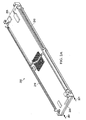
- FIG. 1 illustrates an example system 100 that includes a server rack 105 and an example server rack assembly 110 configured to mount within the rack 105, where the server rack assembly 110 houses one or more heat generating devices.
- the server rack assembly 110 may simply be a flat structure onto which a motherboard may be placed and mounted, so that the assembly 110 may be grasped by technicians for moving the motherboard into place and holding it in position within the rack 105.
- the server rack sub-assembly 110 may be modified (e.g., by implementing it as a peripheral frame around the motherboard) or may be eliminated so that the motherboard itself is located in the rack 105.
- the server rack assembly 110 may be a variety of server structures.
- the server rack assembly 110 may be a "tray" or tray assembly that can be slidingly inserted into the server rack 105.
- a tray can be a flat component with or without a lip or raised edge on one or more edges of the tray.
- the server rack assembly 110 may include multiple sub-assemblies (such as server rack sub-assemblies 200 and 300 described below) on a single tray.
- the server rack assembly 110 may be a hard drive cage.
- the server rack assembly 110 may be a server chassis, or server container ( e.g. , server box).
- the term "tray” is not limited to any particular arrangement, but instead applies to motherboard or other relatively flat structures appurtenant to a motherboard for supporting the motherboard in position in a rack structure. Trays may be generally mounted parallel to other trays in a horizontal or vertical stack, so as to permit denser packing than would otherwise be possible with computers having free-standing housings and other components.
- the term “blade” may also be employed to refer to such apparatuses, though that term too should not be limited to a particular arrangement. Trays may be implemented in particular configurations, including as support for computer servers, switches ( e.g ., electrical and optical), routers, drives or groups of drives, and other computing-related devices. In general, the trays in a system take a standardized physical and electrical form so that they will be easily interchangeable from one location in the system to another, but the trays may take other appropriate forms.
- server rack 105 may be one of a number of server racks within the system 100, which may include a server farm or a co-location facility that contains various rack mounted computer systems.
- the server rack 105 defines multiple slots 107 that are arranged in an orderly and repeating fashion within the server rack 105, such as the illustrated horizontal arrangement, and may each receive one or more server rack assemblies 110 therein.
- Each slot 107 is a space in the rack into which a correspond tray or trays may be placed and removed.
- the slots 107 may be formed, for example, by attaching angle iron pieces (or sheetmetal forms of the rack skin) on opposed lateral sides of the inner part of a rack frame at matched heights on each side, so as to create small shelves over which the trays may be slid and supported.
- the slots 107 may be vertically stacked and receive one or more server rack assemblies 110 mounted in the server rack 105 via mounting rails or other suitable mechanisms.
- Each slot 107 may contain or include any number of server rack assemblies 110 and, typically, may enclose a number of computer components such as central processing units (CPUs), memory, disk drives, power supplies, input/output cards and interfaces, cooling hardware, and other computing devices.
- CPUs central processing units
- memory disk drives
- power supplies input/output cards and interfaces
- cooling hardware and other computing devices.
- Server rack 105 may provide data processing and storage capacity.
- a data center may be connected to a network, and may receive and respond to various requests from the network to retrieve, process, and/or store data.
- the server rack 105 typically facilitates the communication of information over a network with user interfaces generated by web browser applications of users who request services provided by applications running on computers in the datacenter.
- the server rack 105 may provide or help provide a user who is using a web browser to access web sites on the Internet or the World Wide Web.
- Each server rack 105 may house one or more server rack assemblies 110.
- An example implementation of a server rack assembly 110 is illustrated in FIG. 1 .
- the server rack assembly 110 may be mounted flat horizontally in the server rack 105 such as by sliding server rack assembly 110 into a slot 107 of the server rack 105 from the rack front. A technician would be standing in a aisle that runs across the front of a long row of racks.
- the server rack assembly 110 can rest on a pair of rails in the rack 105 located on opposed sides of the server rack assembly 110 - much like sliding a lunch tray into a cafeteria rack, or a tray into a bread rack.
- Server assembly 110 may alternatively be mounted vertically, such as in a bank of trays mounted at one level in the server rack 105.
- the front of the server rack 105 may be kept open to an aisle or workspace during its normal operation (where cooling air may be drawn from the aisle during operation) to permit easy access to, and replacement of, trays and to permit for air to flow over the server rack assembly 110 from the workspace where technicians or other professionals operating a data center may be located.
- the term workspace refers to areas in which technicians or others may normally be located to work on computers in a data center.
- the server rack assembly 110 may include a sub-assembly mounted on the server rack assembly 110.
- the sub-assembly may include a circuit board containing one or more heat generating devices.
- different or additional sub-assemblies may replace or be added to the server rack assembly 110 as, for example, the operation of the server rack 105 may dictate.
- a particular server rack assembly 110 may be retrofit with a sub-assembly including a thermal transfer system (as described below for instance), replacing an existing sub-assembly that did not include the thermal transfer system.
- the retrofitted server rack assembly 110 may be able to address problems associated with heat generated by the computing devices on the sub-assembly better than a more conventional server rack assembly 110 / sub-assembly combination.
- the illustrated server rack assembly 110 houses a motherboard 115 on which a variety of components are mounted. Although one motherboard 115 is illustrated as mounted on server rack assembly 110, multiple motherboards may be mounted on each server rack assembly 110 according to the particular application. In some aspects, the motherboard 115 may be arranged so that air enters at its front edge (at the bottom in the illustrated board 115), is routed over a number of heat generating components on the board 115, and is exhausted from the server rack assembly 110.
- At least one processor 120 and one or more memories 125 may be mounted on the motherboard 115.
- the motherboard 115 may include two, three, four, or any other practicable number of processors 120.
- the motherboard 115 may be replaced with a tray of data storage devices (e.g ., hard disc drives, flash memory, RAM, or any of these or other types of memory in combination).
- the processor 120 may include any combination of analog and/or digital logic circuits, which may be integrated or discrete, and may further include programmable and/or programmed devices that may execute instructions stored in a memory, such as the memory 125.
- the memory or memories 125 may include volatile and/or non-volatile memory that may be read and/or written to by the processor 120.
- the memory 125 may be in the form of a number of single in-line memory modules (SIMMs), dual in-line memory module (DIMMs), or other appropriate form.
- Other components of the computer system such as chip sets and other chips, have been omitted for clarity in the figure, and may be selected and arranged in any appropriate manner.
- the board 115 may also be provided with connections to other devices, such as a network jack in the form of an RJ-45 jack or an optical networking connection.
- Other connections e.g ., besides power connections or other heat generating connections
- a fan 130 may also be arranged to push or pull cooling air over or past one or more of the processor 120, memory 125, and/or other computing devices mounted on the motherboard 115.
- the fan 130 may be mounted on a front side of the board 115 or may be mounted to the server rack assembly 110, and may push cooling air over such components.
- the fan 130 may be mounted at a back edge of the motherboard 115 (or server rack assembly 110) and exhaust air warmed by the illustrated components and other computing devices out of the server rack assembly 110 and/or out of the server rack 105.
- the fan 130 or multiple fans may be arranged to facilitate a cross-flow of cooling air across the motherboard 115 ( e.g ., from left-to-right, or right-to-left, as opposed to front-to-back or back-to-front) to dissipate heat generated by the processor 120, memory 125, and/or other heat-generating components.
- the cooling air may include ambient air drawn from a human-occupiable workspace that is then routed over the motherboard 115 by the fan 130 or other air moving device.
- the cooling air may be ambient air that has been mechanically cooled ( e.g ., through a cooling coil, by evaporative cooling, or other cooling techniques) before being drawn over the motherboard 115.
- cooling fluid such as cold or ambient air, may be provided over the motherboard 115 by the fan 130, other air moving device, natural convective airflows through the server rack 105, and/or a combination thereof.
- the motherboard 115 and/or server rack assembly 110 may not include fan 130 or any air moving device mounted thereon.
- one or more fans located elsewhere in system 100 such as exhaust fans located in ductwork, supply fans located in computer-room air conditioners (CRACs), fan coil units, warm-air plenums, or other air handling equipment, may circulate cooling air over at least a portion of the board 115 (and may in certain implementations supplement fans mounted on the boards or trays).
- the board 115 may include one or more portions or areas in which air movement (such as by fan 130 or another air moving device) is minimal or substantially non-existent.
- these areas that experience minimal or no airflow may experience minimal or no convective heat transfer of heat generated by the processor 120, the memory 125, and/or other computing devices via a cooling airflow.
- all or substantially all of the board 115 and/or server rack assembly 110 may experience minimal or substantially no convective heat transfer via a cooling airflow over a middle portion of the board 115.
- cooling airflow may be circulated over or past one or more edges of the motherboard 115, minimal or no airflow may be circulated over heat-generating devices mounted at or towards the middle area of the board 115.
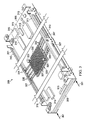
- FIGs. 2A-2C illustrate top and bottom views of one example implementation of a server rack sub-assembly 200 including a thermal transfer system.
- the server rack sub-assembly 200 may be one of several sub-assemblies, or alternatively the only sub-assembly, mounted on the server rack assembly 110 illustrated in FIG. 1 and configured to slide into one of the slots 107 in the server rack 105.
- server rack sub-assembly 200 may itself be configured to slide into one of the slots 107 in the server rack 105 adjacent one or more other server rack sub-assemblies 200 and/or server rack assemblies 110.
- the server rack sub-assembly 200 houses one or more electronic devices 215 mounted on a motherboard 205 that facilitate data processing, data storage, network communication, or any other computing functionality and/or environment. Such devices 215 may generate heat during their operation, such as heat generated due to electrical inefficiencies of the devices 215. Electronic devices 215 may be mounted to the motherboard 205 (e.g ., circuit card or PCB, field programmable gate array (FPGA)) through any appropriate techniques. Although FIG. 2B illustrates a single motherboard 205, multiple motherboards 205 may be mounted together with electronic devices 215 mounted thereon. In some implementations, one or more structural components of the server rack sub-assembly 200 may function as a heat sink and, for example, may work in conjunction with heat sink 220 thermally coupled to the sub-assembly 200.
- a heat sink e.g a heat sink
- heat sink 220 thermally coupled to the sub-assembly 200.
- Server rack sub-assembly 200 also includes brackets 210 that are mounted on one or more edges of the motherboard 205.
- the brackets 210 may be configured to couple two or more motherboards 205 together.
- the brackets 210 may include space for three motherboards 205 to be coupled thereto, thereby providing a supporting structure for mounting the motherboards 205 to, for example, the server rack assembly 110.
- the brackets 210 may facilitate or help facilitate installation of the server rack sub-assembly 200 into the server rack 105.
- additional components such as one or more rails (not shown) may be mounted to the brackets to help facilitate installation of the server rack sub-assembly 200 onto the server rack assembly 110 and/or into the server rack 105.
- the brackets 210 may provide structural stability or rigidity to the server rack sub-assembly 200.
- the brackets 210 may provide the structural components to physically couple the heat sink 220, the motherboards 205, a heat pipe 230 and/or combinations of some of these components of the server rack sub-assembly 200.
- the brackets 210 may provide the structural components to physically couple the server rack sub-assembly 200 to, for example, the server rack assembly 110 and/or corresponding structures in the server rack 105.
- the brackets 210 may be a heat sink component or a portion of a heat sink component that conducts heat from one or more of the electronic devices 215.
- the brackets 210 may be integral with all or a portion of the a heat sink component that is in direct contact with a motherboard and/or electronic components on a motherboard.
- the brackets 210 may be made of aluminum, copper, or other material which has good thermal conductivity.
- one or more of the brackets 210 when installed as part of the server rack sub-assembly 200 and installed in the server rack 105, may be located within a cooling airflow circulated within the server rack 105.
- the cooling airflow (such as cooling airflow 201 illustrated in FIG. 2B ) may be circulated over the brackets 210 only without being circulated over other portions of the server rack sub-assembly 200.
- the heat sink 220 may be mounted to the motherboard 205 via one or more retainers 225.
- the retainers 225 may be inserted through one or more apertures of the heat sink 220 aligned with one or more apertures through the board 205.
- the heat sink 220 may be mounted to the board 205 by depressing the retainers 225 through the corresponding apertures aligned through the board 205 and the heat sink 220.
- installation of the heat sink 220 to the board 205 may provide for a small or slight air gap between a bottom portion of the heat sink 220 (shown in FIG. 2C ) and the board 205.
- This air gap may be filled in to create contact between the heat sink 220 and the board 205 and/or devices 215 through, for example, a thermal interface as shown in FIG 2C and discussed in more detail below.
- the motherboard 205 is mounted to the brackets 210 at four separate locations via mechanical fasteners.
- motherboard 205 may be mounted to the brackets 210 at any number of locations, at locations different than those shown in FIGS. 2A-2C , and by mounting techniques different or in addition to those illustrated.
- the motherboard 205 is illustrated as being mounted to the brackets 210 at or near the four corners of the board 205, the motherboard 205 may extend past the brackets 210 lengthwise, such that the brackets 210 are coupled to the board 205 at or near a middle portion of the board 205, but do not extend to an end of the board 205.
- the motherboard 205 may be part of a sub-assembly (like the server rack sub-assembly 200) in which the board 205 is not mounted to any brackets. Instead, in these alternative implementations, the motherboard 205 may be mechanically coupled to the server rack sub-assembly 200 (or a tray such as the server rack assembly 110, or a server rack structure such as the server rack 105).
- One or more brackets 210 may include one or more apertures 207.
- Apertures 207 may help facilitate attachment and/or coupling of the server rack sub-assembly 200 to a server rack assembly 110 and/or one or more rails (not shown) used to facilitate installation of the server rack sub-assembly 200 into the server rack 105 and/or into a server tray. Additionally, in some implementations, apertures 207 may serve to increase a heat transfer area of the bracket 210 as cooling air 201 is passed over the bracket 210.
- bracket 210 As convective heat transfer between the bracket 210 and the cooling airflow is directly related to a surface area of the bracket 210 exposed to the cooling airflow, increasing such area of the bracket 210 by forming one or more apertures 207 in the bracket 210 may increase the convective heat transfer from the bracket 210 to the airflow (such as airflow 201).
- the server rack sub-assembly 200 also includes a heat sink 220 mounted to the motherboard 205 via one or more retainers 225.
- Heat sink 220 includes a planar portion 223 on which multiple fins 227 are integrally mounted thereon.
- heat sink 220 is in physical contact with at least a portion of the board 205 and/or at least some of the electronic devices 215 (as described further herein).
- a bottom side of the heat sink 220 is illustrated, including the planar portion 223 and a thermal interface 235.
- the planar portion 223 may be substantially planar with a recessed area or cutout on a bottom side of the portion 223.
- a top side of the planar portion 223 (shown in FIG. 2B ) may be substantially flat.
- portion 223 of the heat sink 220 is substantially planar, at least some of the portion 223 may be recessed.
- Thermal interface 235 generally, facilitates or helps facilitate physical contact between the heat sink 220 and the motherboard 205 and/or one or more heat generating components on the motherboard 205.
- the thermal interface 235 includes a film 237 covering a thermal material 240.
- the thermal material 240 may, in some implementations, be a phase-change material such that as a temperature of the material 240 increases, the material 240 changes phase (e.g., solid to liquid, solid to near liquid, solid to semi-solid, and otherwise).
- the thermal material 240 may flow towards the board 205 and/or electronic devices 215 in order to increase a contact area between the film 237 and the board 205 ( e.g ., by filling in an air gap between the board 205 and the heat sink 220 and/or filling in an irregular surfaces of the board 205 (or devices 215) and/ the heat sink 220).
- the thermal material 240 may flow to fill in small imperfections (e.g ., irregularities and/or roughened surfaces) between a base of the heat sink 220 and an outer covering ( i.e. , outer surface of one or more electronic devices 215).
- small imperfections e.g ., irregularities and/or roughened surfaces
- an outer covering i.e. , outer surface of one or more electronic devices 215.
- the air gap between the board 205 and electronic devices 215, or one of the board 205 or a portion of the electronic device 215, may be microscopic.
- the air gap may be due to surface imperfections on the heat sink 220 and the board 205 and/or the electronic devices 215.
- the thermal interface 235 may not include the film 237.
- the thermal material 240 may flow to directly contact the board 205.
- the thermal material 240 as it changes phase to a liquid and/or a semi-solid material, may create an adhesive interface between the heat sink 220 and the board 205.
- heat generated by the electronic devices 215 may be conductively transferred to the heat sink 220 via the thermal interface 235.
- heat generated by the electronic devices 215, which may or may not have a cooling airflow 201 circulated over such devices 215, may be removed or partially removed from the devices 215 to the heat sink 220.
- the server rack sub-assembly 200 includes a heat pipe 230 mounted to the heat sink 220 and the brackets 210. Heat generated by the electronic devices 215 transferred to the heat sink 220 may be transferred to the heat pipe 230. Heat pipe 230, for example, may utilize heat transfer via conduction and phase transition of a working material (e.g ., a fluid like a liquid or gas, or a gel, or other material) within the heat pipe 230 to transfer heat from the heat sink 220 to one or more of the brackets 210.
- a working material e.g ., a fluid like a liquid or gas, or a gel, or other material
- a working material within the pipe 230 e.g ., water, liquid helium, mercury, sodium, indium, ammonia, alcohol, or otherwise
- a working material within the pipe 230 e.g ., water, liquid helium, mercury, sodium, indium, ammonia, alcohol, or otherwise
- the portion of the heat pipe 230 in which the working material evaporates may be an evaporator section.
- the evaporated working material of the heat pipe 230 may travel ( e.g ., via pressure and/or thermal gradients) from a middle portion of the heat pipe 230 to ends of the heat pipe 230 mounted to the brackets 210. As the evaporated working material nears such ends of the heat pipe 230 in contact with the brackets 210 (which are at a lower temperature than the evaporated working material due to, for example, the cooling airflow 201), it condenses back into a liquid, thereby releasing the heat transferred from the heat sink 220 to the brackets 210.
- the portion of the heat pipe 230 in which the working material condenses may be an condenser section.
- the working material may then move back towards the middle portion of the heat pipe 230 (e.g ., by pressure gradients, temperature gradients, and or by gravitational force) and the above-described heat transfer cycle may be repeated.
- the heat pipe 230 may be a thermosiphon.
- a thermal circuit may exist such that heat energy travels from the electronic devices 215 and/or motherboard 205 to the thermal interface 235 of the heat sink 220, from the thermal interface 235 to the planar portion 223 of the heat sink 220, from the planar portion 223 to the heat pipe 230 and thus to the working material of the heat pipe 230, and from the working material to the brackets 210.
- heat generated by components on the server rack sub-assembly 200 that may experience minimal or no cooling airflow convection heat transfer may be transferred to one or more components, such as brackets 210, that experience convection heat transfer due to cooling airflow 201.
- the components of the server rack sub-assembly 200 within the thermal circuit may define a thermal transfer system for use with the server rack sub-assembly 200.
- a heat transfer device may be utilized in place of the heat pipe 230 in order to transfer heat generated by the electronic devices 215, and conductively transferred to the heat sink 220, to the brackets 210.
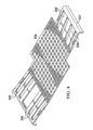
- FIG. 3 illustrates a top view of another example implementation of a server rack sub-assembly 300 including a thermal transfer system.
- the server rack sub-assembly 300 may be substantially similar to the server rack assembly 110 illustrated in FIG. 1 and configured to slide into one of the slots 107 in the server rack 105.
- the server rack sub-assembly 300 may be coupled and/or attached to one or more server rack assemblies 110 illustrated in FIG. 1 .
- server rack sub-assembly 300 may itself be configured to slide into one of the slots 107 in the server rack 105 adjacent one or more other server rack sub-assemblies 300, server rack sub-assemblies 200, and/or server rack assemblies 110.
- server rack sub-assembly 300 may be used in place of, or in addition to, server rack sub-assembly 200 in server rack 105.
- the server rack sub-assembly 300 has one or more electronic devices 315 mounted on a motherboard 305 that facilitate data processing, data storage, network communication, or any other computing functionality and/or environment. Such devices 315 may generate heat during their operation, such as heat generated due to electrical inefficiencies of the devices 315. Electronic devices 315 may be mounted to the motherboard 305 (e.g ., circuit card or PCB, field programmable gate array (FPGA)) through any appropriate techniques. Although FIG. 3 illustrates a single motherboard 305, multiple motherboards 305 may be mounted together with electronic devices 315 mounted thereon.
- the motherboard 305 e.g ., circuit card or PCB, field programmable gate array (FPGA)
- Server rack sub-assembly 300 also has brackets 310 mounted on one or more edges of the motherboard 305.
- the brackets 310 may be configured to couple two or more motherboards 305 together.
- the brackets 310 may facilitate or help facilitate mounting of the server rack sub-assembly 300 to a server rack assembly 110 (shown in FIG 1 ) and/or installation of the server rack sub-assembly 300 into the server rack 105.
- additional components such as one or more rails (not shown) may be mounted to the brackets to help facilitate installation of the server rack sub-assembly 300 onto the server rack assembly 110 and/or into the server rack 105.
- the brackets 310 may be made of aluminum, copper, or other material which has good thermal conductivity.
- one or more of the brackets 310 when installed as part of the server rack sub-assembly 300 and installed in the server rack 105, may be located within a cooling airflow circulated within the server rack 105.
- the cooling airflow (such as cooling airflow 301 illustrated in FIG. 3 ) may be circulated over the brackets 310 only without being circulated over other portions of the server rack sub-assembly 300.
- the heat sink 320 may be mounted to the motherboard 305 via one or more retainers 325.
- the retainers 325 may be inserted through one or more apertures of the heat sink 320 aligned with one or more apertures through the board 305.
- the heat sink 320 may be mounted to the board 305 by depressing the retainers 325 through the corresponding apertures aligned through the board 305 and the heat sink 320. By mounting the heat sink 320 to the motherboard 305, physical contact between the heat sink 320 and board 305 (and/or heat sink 320 and electronic devices 315) may be created.
- installation of the heat sink 320 to the board 305 may provide for a small or slight air gap between a bottom portion of the heat sink 320 and the board 305 (or devices 315).
- This air gap may be filled in to create contact between the heat sink 320 and the board 305 (or devices 315) through, for example, a thermal interface 235 as shown in FIG. 2C .
- the motherboard 305 is mounted to the brackets 310 at four separate locations via mechanical fasteners.
- motherboard 305 may be mounted to the brackets 310 at any number of locations, at locations different than those shown in FIG. 3 , and by mounting techniques different or in addition to those illustrated.
- the motherboard 305 is illustrated as being mounted to the brackets 310 at or near the four corners of the board 305, the motherboard 305 may extend past the brackets 310 lengthwise, such that the brackets 310 are coupled to the board 305 at or near a middle portion of the board 305.
- Brackets 310 may include one or more apertures 307.
- Apertures 307 may help facilitate attachment and/or coupling of the server rack sub-assembly 300 to a server rack assembly 110 and/or one or more rails (not shown) used to facilitate installation of the server rack sub-assembly 300 into the server rack 105. Additionally, in some implementations, apertures 307 may serve to increase a heat transfer area of the bracket 310 as cooling air is passed over the bracket 310.
- the bracket 310 may increase the convective heat transfer from the bracket 310 to the airflow 301.
- the one or more apertures 307 may facilitate or help facilitate airflow to certain portions of the server rack sub-assembly 300, such as a middle portion of the motherboard 305.
- the server rack sub-assembly 300 has a heat sink 320 mounted to the motherboard 305 via one or more retainers 325.
- Heat sink 320 as illustrated, includes a planar portion 323 on which multiple fins 327 are integrally mounted thereon.
- heat sink 320 is in physical contact with at least a portion of the board 305 (described with reference to FIGs. 2A-2C above).
- heat generated by the electronic devices 315 may be conductively transferred to the heat sink 320 via a thermal interface, such as a thermal interface similar to thermal interface 235, as shown in FIG. 2C .
- a thermal interface such as a thermal interface similar to thermal interface 235, as shown in FIG. 2C .
- heat generated by the electronic devices 315 which may or may not have a cooling airflow 301 circulated over such devices 315, may be removed or partially removed from the devices 315 to the heat sink 320.
- the server rack sub-assembly 300 may provide for a thermal mesh 330 mounted to the heat sink 220 and the brackets 210.
- the thermal mesh 330 is installed over one or more of the fins 327 of the heat sink 320 such that the mesh 330 is in at least thermal communication with the heat sink 320 via the planar portion 323 and/or the fins 327.
- the thermal mesh 330 may be configured and installed to rest on the planar portion 323 of the heat sink 320.
- the thermal mesh 330 includes one or more wings 335 extending from a grid portion of the mesh 330 and configured to be coupled to the brackets 310.
- the wings 335 may be formed with an edge 337 to fit under, and be held in place by, a lip 311 on each bracket 310.
- the lips 311 may constrain the wings 335 and thus constrain the thermal mesh 330 onto the heat sink 320 even without mechanical or adhesive fastening techniques applied between the wings 335 and the lips 311.
- the wings 335 may be in the form of thermally conductive strips of material (e.g ., aluminum and/or copper) that are adhered to or integral with the thermal mesh 330. In the forms of strips, the wings 335 may have greater flexibility and thus, a greater spring force.
- the thermal mesh 330 may include a curvature such that edges of the mesh 330 from which the wings 335 extend curve upward. In such implementations, when the wings 335 are constrained by the lips 311 of the brackets 310, a downwardly directed force may be applied to the wings 335.
- the thermal mesh 330 When such force, F, is applied, the thermal mesh 330 may be urged downward to create more physical contact between the mesh 330 and the planar portion 323 of the heat sink 320. Further, in some implementations, the thermal mesh 330 may also have a slight interference fit with the heat sink 220 in order to increase a contact force between the fins 327 and the mesh 330.
- Thermal mesh 330 may conduct such heat through the wings 335 and to the brackets 310 that are in thermal contact with the wings 335.
- a thermal circuit may exist such that heat energy travels from the electronic devices 315 and/or motherboard 305 to a thermal interface (if provided) of the heat sink 320, from the thermal interface to the planar portion 323 of the heat sink 320, from the planar portion 323 to the outer thermal mesh 330, from the thermal mesh 330 through the wings 335, and from the wings 335 to the brackets 310.
- heat that may be generated by components on the server rack sub-assembly 300 that may experience minimal or no cooling airflow convection heat transfer may be transferred to one or more components, such as brackets 310, that experience convection heat transfer due to cooling airflow 301.
- the components of the server rack sub-assembly 300 within the thermal circuit may define a thermal transfer system for use with the server rack sub-assembly 300.
- the wings 335 may facilitate convective heat transfer from the thermal mesh 330 as cooling airflow 301 is circulated over the brackets 310 and at least portions of the wings 335.
- fins 227 and/or fins 327 may facilitate convective heat transfer from heat sinks 220 and 320, respectively, to cooling airflow 301. Fins 227 and/or fins 327 may also facilitate conductive heat transfer from heat sinks 220 and 320, respectively, air that is stationary around and adjacent the fins. Accordingly, other implementations are within the scope of the following claims.
Landscapes
- Engineering & Computer Science (AREA)
- Microelectronics & Electronic Packaging (AREA)
- Physics & Mathematics (AREA)
- Thermal Sciences (AREA)
- Computer Hardware Design (AREA)
- General Engineering & Computer Science (AREA)
- Cooling Or The Like Of Electrical Apparatus (AREA)
Claims (19)
- Sous-ensemble (110) de bâti de serveur, comportant :au moins une carte-mère (115, 205, 305) présentant un périmètre ;une pluralité de dispositifs électroniques thermogènes (120, 125, 215, 315) montés sur la carte-mère dans une zone de la carte-mère découplée thermiquement du périmètre de la carte-mère ;un ou plusieurs supports (210, 310) comportant des surfaces de transfert de chaleur et fixés à la carte-mère le long d'au moins une partie du périmètre de la carte-mère, le ou les supports étant prévus pour recevoir un flux (201, 301) d'air de refroidissement mis en circulation au-dessus du support et pour transférer par convection de la chaleur dans le flux d'air de refroidissement, le ou les supports étant prévus pour coupler la carte-mère à un ensemble de bâti de serveur ; etun dispositif (230, 335) de transfert de chaleur couplé thermiquement à la zone de la carte-mère qui est découplée thermiquement du périmètre de la carte-mère et du ou des supports, le dispositif de transfert de chaleur étant agencé de façon à transférer par convection de la chaleur du ou des dispositifs électroniques aux supports.
- Sous-ensemble de bâti de serveur selon la revendication 1, comportant en outre un dissipateur thermique (220, 320) monté sur la carte-mère dans la zone de la carte-mère découplée thermiquement du périmètre de la carte-mère, le dissipateur thermique étant couplé thermiquement à la zone de la carte-mère et au dispositif de transfert de chaleur.
- Sous-ensemble de bâti de serveur selon la revendication 1, au moins une partie du dissipateur thermique comprenant le ou les supports.
- Sous-ensemble de bâti de serveur selon la revendication 2, le dissipateur thermique comportant une interface thermique (235) entre au moins une partie de la pluralité de dispositifs électroniques thermogènes et une partie planaire du dissipateur thermique, l'interface thermique étant prévue pour accroître le contact entre la partie de la pluralité de dispositifs électroniques thermogènes et le dissipateur thermique à mesure qu'une température du dissipateur thermique augmente.
- Sous-ensemble de bâti de serveur selon la revendication 4, l'interface thermique comportant un matériau à changement de phase enveloppé contre la partie planaire du dissipateur thermique par un film, le matériau à changement de phase étant prévu pour se transformer d'un matériau sensiblement solide en un matériau semi-solide ou liquide à mesure que la température du dissipateur thermique augmente.
- Sous-ensemble de bâti de serveur selon la revendication 5, le matériau à changement de phase transformé remplissant sensiblement un interstice entre la partie de la pluralité de dispositifs électroniques thermogènes et le dissipateur thermique, ou le matériau à changement de phase transformé remplissant sensiblement un interstice entre la carte-mère et le dissipateur thermique.
- Sous-ensemble de bâti de serveur selon la revendication 1, le dispositif de transfert de chaleur comportant un caloduc (220) renfermant un matériau de travail.
- Sous-ensemble de bâti de serveur selon la revendication 7, le caloduc comportant en outre un évaporateur et au moins un condenseur, l'évaporateur étant couplé thermiquement à la zone de la carte-mère découplée thermiquement du périmètre, le condenseur étant couplé thermiquement à un ou plusieurs des supports ou le matériau de travail étant prévu pour recevoir la chaleur générée par les dispositifs électroniques et transférer la chaleur au(x) support(s).
- Sous-ensemble de bâti de serveur selon la revendication 2, le dispositif de transfert de chaleur comportant une grille (330) couplée thermiquement à la zone de la carte-mère qui est découplée thermiquement du périmètre et d'au moins un des supports.
- Sous-ensemble de bâti de serveur selon la revendication 9, le dissipateur thermique comportant en outre une ou plusieurs ailettes (327) s'étendant à partir d'une partie planaire du dissipateur thermique,
et
la grille étant couplée au dissipateur thermique par-dessus les ailettes de telle façon que la grille et le dissipateur thermique soient en contact thermique, ou la grille comportant une ou plusieurs ailes (335) s'étendant à partir d'une partie sensiblement planaire de la grille, les ailes étant prévues pour communiquer thermiquement de la chaleur de la partie planaire de la grille à au moins un des supports. - Procédé de refroidissement d'équipement électronique, comportant les étapes consistant à :mettre en place au moins un sous-ensemble (110) de bâti de serveur comportant au moins une carte-mère (115, 205, 305) et un ou plusieurs supports (210, 310) couplés à la carte-mère le long d'au moins une partie d'un périmètre de la carte-mère, le ou les supports étant prévus pour coupler la carte-mère à un ensemble de bâti de serveur, la carte-mère comportant une pluralité de dispositifs informatiques thermogènes (120, 215, 315) montés sur la carte-mère dans une zone découplée thermiquement du périmètre ;faire circuler un flux (201, 301) d'air de refroidissement dirigé par-dessus le ou les supports au voisinage du périmètre ;transférer par conduction de la chaleur générée par la pluralité de dispositifs informatiques montés sur the découplée thermiquement area to le ou les supports ; ettransférer par convection la chaleur générée du ou des supports au flux d'air de refroidissement.
- Procédé selon la revendication 11, comportant en outre les étapes consistant à :transférer par conduction de la chaleur générée par la pluralité de dispositifs informatiques montés sur la zone découplée thermiquement à un dissipateur thermique (220, 320) monté sur la carte-mère dans la zone découplée thermiquement du périmètre ; ettransférer par conduction la chaleur du dissipateur thermique aux supports.
- Procédé selon la revendication 12, comportant en outre l'étape consistant à :transférer par conduction de la chaleur générée par la pluralité de dispositifs informatiques montés sur la zone découplée thermiquement au dissipateur thermique par l'intermédiaire d'une interface thermique (235) entre le dissipateur thermique et la carte-mère,l'interface thermique comportant un matériau à changement de phase.
- Procédé selon la revendication 11, le transfert par conduction de la chaleur générée par la pluralité de dispositifs informatiques montés sur la zone découplée thermiquement au(x) support(s) comportant l'étape consistant à transférer par conduction de la chaleur générée par la pluralité de dispositifs informatiques montés sur la zone découplée thermiquement au(x) support(s) à l'aide d'un caloduc (230) couplé thermiquement à la carte-mère et au(x) support(s), le caloduc comportant un matériau de travail confiné dans un évaporateur en communication fluidique avec un condenseur.
- Procédé selon la revendication 14, comportant en outre les étapes consistant à :transférer la chaleur générée de la pluralité de dispositifs informatiques montés sur la zone découplée thermiquement au matériau de travail situé à l'intérieur de l'évaporateur ; ettransférer la chaleur générée du matériau de travail au (x) support(s).
- Procédé selon la revendication 12, le transfert par conduction de la chaleur générée par la pluralité de dispositifs informatiques montés sur la zone découplée thermiquement au périmètre comportant l'étape consistant à transférer par conduction de la chaleur générée par la pluralité de dispositifs informatiques montés sur la zone découplée thermiquement au périmètre à l'aide d'une grille (330) couplée thermiquement à la carte-mère et au périmètre, la grille comportant une pluralité d'ouvertures et une ou plusieurs ailes (335).
- Procédé selon la revendication 16, comportant en outre les étapes consistant à :coupler la grille au dissipateur thermique en faisant coulisser la pluralité d'ouvertures par-dessus des ailettes (327) correspondantes montées sur le dissipateur thermique ; coupler chaque aile à un support correspondant au voisinage du périmètre ; ettransférer par conduction la chaleur générée à partir de la pluralité de dispositifs informatiques montés sur la zone découplée thermiquement, à travers l'aile et jusqu'au support correspondant.
- Système comportant :un ensemble (100) de bâti de serveur comportant au moins deux sous-ensembles de bâti de serveur, au moins un des sous-ensembles de bâti de serveur étant le sous-ensemble (110) de bâti de serveur selon la revendication 1 ou 2 et comportant en outre :un ou plusieurs ventilateurs (130) prévus pour faire circuler de l'air de refroidissement par-dessus les surfaces de transfert de chaleur pour évacuer par convection de la chaleur à partir de la zone de la carte-mère qui est découplée thermiquement du périmètre de la carte-mère et du ou des supports, le ou les supports (210, 310) couplant le sous-ensemble (110) de bâti de serveur à l'ensemble (100) de bâti de serveur.
- Système selon la revendication 18, le ou au moins un des ventilateurs étant montés sur l'ensemble de bâti de serveur, ou le ou les ventilateurs ne faisant pas circuler l'air par-dessus la zone de la carte-mère découplée thermiquement du périmètre de la carte-mère.
Priority Applications (1)
| Application Number | Priority Date | Filing Date | Title |
|---|---|---|---|
| EP14160571.7A EP2750493B1 (fr) | 2010-12-01 | 2011-12-01 | Refroidissement de dispositifs électroniques thermogènes |
Applications Claiming Priority (2)
| Application Number | Priority Date | Filing Date | Title |
|---|---|---|---|
| US12/957,855 US8644020B2 (en) | 2010-12-01 | 2010-12-01 | Cooling heat-generating electronics |
| PCT/US2011/062907 WO2012075300A1 (fr) | 2010-12-01 | 2011-12-01 | Refroidissement d'éléments électroniques thermogènes |
Related Child Applications (1)
| Application Number | Title | Priority Date | Filing Date |
|---|---|---|---|
| EP14160571.7A Division EP2750493B1 (fr) | 2010-12-01 | 2011-12-01 | Refroidissement de dispositifs électroniques thermogènes |
Publications (2)
| Publication Number | Publication Date |
|---|---|
| EP2647273A1 EP2647273A1 (fr) | 2013-10-09 |
| EP2647273B1 true EP2647273B1 (fr) | 2014-04-02 |
Family
ID=45390185
Family Applications (2)
| Application Number | Title | Priority Date | Filing Date |
|---|---|---|---|
| EP14160571.7A Active EP2750493B1 (fr) | 2010-12-01 | 2011-12-01 | Refroidissement de dispositifs électroniques thermogènes |
| EP11799544.9A Active EP2647273B1 (fr) | 2010-12-01 | 2011-12-01 | Refroidissement d'éléments électroniques thermogènes |
Family Applications Before (1)
| Application Number | Title | Priority Date | Filing Date |
|---|---|---|---|
| EP14160571.7A Active EP2750493B1 (fr) | 2010-12-01 | 2011-12-01 | Refroidissement de dispositifs électroniques thermogènes |
Country Status (6)
| Country | Link |
|---|---|
| US (2) | US8644020B2 (fr) |
| EP (2) | EP2750493B1 (fr) |
| CN (1) | CN103329641B (fr) |
| SG (1) | SG190896A1 (fr) |
| TW (1) | TWI559844B (fr) |
| WO (1) | WO2012075300A1 (fr) |
Families Citing this family (53)
| Publication number | Priority date | Publication date | Assignee | Title |
|---|---|---|---|---|
| US8850816B2 (en) * | 2010-05-11 | 2014-10-07 | Dell Products L.P. | Power regeneration for an information handling system |
| US8644020B2 (en) * | 2010-12-01 | 2014-02-04 | Google Inc. | Cooling heat-generating electronics |
| DE112011105205B4 (de) * | 2011-06-27 | 2016-05-12 | Hewlett-Packard Development Company, L.P. | Wärmesenke, System und Verfahren zum Kühlen von Komponenten |
| AU2012232967B2 (en) | 2011-10-31 | 2015-01-15 | Abb Technology Ag | Cabinet with modules having a thermosiphon cooler arrangement |
| AU2012232968B2 (en) * | 2011-10-31 | 2014-11-13 | Abb Technology Ag | Thermosiphon cooler arrangement in modules with electric and/or electronic components |
| US8617927B1 (en) | 2011-11-29 | 2013-12-31 | Hrl Laboratories, Llc | Method of mounting electronic chips |
| JP5797329B2 (ja) * | 2012-04-19 | 2015-10-21 | 株式会社日立製作所 | 冷却システムを備えた電子計算機 |
| CN104509220B (zh) | 2012-05-07 | 2018-05-29 | 弗诺尼克设备公司 | 包括保护性热密封盖和最优化界面热阻的热电热交换器组件 |
| US20130291555A1 (en) | 2012-05-07 | 2013-11-07 | Phononic Devices, Inc. | Thermoelectric refrigeration system control scheme for high efficiency performance |
| FR2995172B1 (fr) * | 2012-09-06 | 2015-11-20 | Sagemcom Broadband Sas | Equipement electronique a refroidissement par air et dispositif de refroidissement d'un composant electronique |
| CN104508592B (zh) | 2012-09-28 | 2018-10-30 | 慧与发展有限责任合伙企业 | 用于可移除模块的送气室 |
| US9229497B2 (en) | 2012-11-08 | 2016-01-05 | Silicon Graphics International Corp. | On-blade cold sink for high-density clustered computer system |
| US20140188283A1 (en) * | 2012-12-28 | 2014-07-03 | Prosenjit Ghosh | Adjusting performance range of computing device |
| CN103237412B (zh) * | 2013-03-27 | 2016-03-23 | 苏州远创达科技有限公司 | 一种电子件安装结构及制作方法、电子件产品 |
| US10079160B1 (en) | 2013-06-21 | 2018-09-18 | Hrl Laboratories, Llc | Surface mount package for semiconductor devices with embedded heat spreaders |
| CN104613556A (zh) * | 2013-11-04 | 2015-05-13 | 珠海格力电器股份有限公司 | 电器元件的散热装置及具有其的空调器 |
| US9405335B1 (en) * | 2014-02-21 | 2016-08-02 | Google Inc. | Heat pipe cooling arrangement |
| USD748093S1 (en) | 2014-07-10 | 2016-01-26 | Bae Systems Information And Electronic Systems Integration Inc. | Data storage transfer archive repository |
| USD748638S1 (en) | 2014-07-10 | 2016-02-02 | Bae Systems Information And Electronic Systems Integration Inc. | Front panel with openings for air cooling a data storage transfer archive repository |
| USD748627S1 (en) | 2014-07-10 | 2016-02-02 | Bae Systems Information And Electronic Systems Integration Inc. | Front panel with openings for air cooling a data storage transfer archive repository |
| ES2770014T3 (es) | 2014-07-21 | 2020-06-30 | Phononic Devices Inc | Sistemas y métodos para el funcionamiento de un módulo termoeléctrico para aumentar la eficiencia |
| US9398731B1 (en) | 2014-09-23 | 2016-07-19 | Google Inc. | Cooling electronic devices in a data center |
| US9337124B1 (en) * | 2014-11-04 | 2016-05-10 | Hrl Laboratories, Llc | Method of integration of wafer level heat spreaders and backside interconnects on microelectronics wafers |
| WO2016114791A1 (fr) | 2015-01-16 | 2016-07-21 | Hewlett Packard Enterprise Development Lp | Plénum pour fournir de l'air frais et acheminer de multiples câbles |
| EP3266288A4 (fr) * | 2015-04-20 | 2018-11-14 | Hewlett Packard Enterprise Development LP | Refroidissement à air supplémentaire |
| US10448543B2 (en) | 2015-05-04 | 2019-10-15 | Google Llc | Cooling electronic devices in a data center |
| US9385083B1 (en) | 2015-05-22 | 2016-07-05 | Hrl Laboratories, Llc | Wafer-level die to package and die to die interconnects suspended over integrated heat sinks |
| US10462935B2 (en) | 2015-06-23 | 2019-10-29 | Google Llc | Cooling electronic devices in a data center |
| US10265812B2 (en) * | 2015-08-12 | 2019-04-23 | International Business Machines Corporation | Liquid-cooled, composite heat sink assemblies |
| US10026672B1 (en) | 2015-10-21 | 2018-07-17 | Hrl Laboratories, Llc | Recursive metal embedded chip assembly |
| US9508652B1 (en) | 2015-11-24 | 2016-11-29 | Hrl Laboratories, Llc | Direct IC-to-package wafer level packaging with integrated thermal heat spreaders |
| US10349561B2 (en) | 2016-04-15 | 2019-07-09 | Google Llc | Cooling electronic devices in a data center |
| CN106304797B (zh) * | 2016-09-29 | 2019-03-08 | 努比亚技术有限公司 | 一种移动终端 |
| CN106455428B (zh) * | 2016-09-29 | 2018-12-21 | 努比亚技术有限公司 | 一种移动终端 |
| CN106455427B (zh) * | 2016-09-29 | 2019-03-05 | 努比亚技术有限公司 | 一种移动终端 |
| CN106455429B (zh) * | 2016-09-29 | 2019-01-15 | 努比亚技术有限公司 | 一种导热部件的密封方法 |
| CN106455426B (zh) * | 2016-09-29 | 2019-06-07 | 努比亚技术有限公司 | 一种导热部件的密封方法 |
| CN106413345B (zh) * | 2016-09-29 | 2019-01-15 | 努比亚技术有限公司 | 一种导热部件的密封方法 |
| US10415474B2 (en) | 2017-01-31 | 2019-09-17 | General Electric Company | Method and system for phase change material component cooling |
| CN107979955B (zh) * | 2017-11-24 | 2020-06-30 | 北京百度网讯科技有限公司 | 一种模块化液冷服务器机箱 |
| CN108495516B (zh) * | 2018-04-26 | 2023-12-19 | 湖北三江航天万峰科技发展有限公司 | 一种基于流体介质散热的板卡组件及安装板卡组件的设备 |
| US11051431B2 (en) * | 2018-06-29 | 2021-06-29 | Juniper Networks, Inc. | Thermal management with variable conductance heat pipe |
| US10950562B1 (en) | 2018-11-30 | 2021-03-16 | Hrl Laboratories, Llc | Impedance-matched through-wafer transition using integrated heat-spreader technology |
| US10548240B1 (en) * | 2019-01-11 | 2020-01-28 | Google Llc | Cooling electronic devices in a data center |
| US11765871B2 (en) * | 2020-03-26 | 2023-09-19 | Ge Aviation Systems Llc | Aircraft and method for thermal management |
| US11860067B2 (en) * | 2021-01-19 | 2024-01-02 | Nvidia Corporation | Thermal test vehicle |
| US12156384B2 (en) * | 2021-05-07 | 2024-11-26 | Nvidia Corporation | Modular thermal test vehicle |
| JP7687136B2 (ja) * | 2021-08-23 | 2025-06-03 | 富士フイルムビジネスイノベーション株式会社 | 基板構造及び電子機器 |
| US11950354B2 (en) | 2022-03-04 | 2024-04-02 | Apple Inc. | Internal architecture of a computing device |
| US12046534B2 (en) | 2022-03-04 | 2024-07-23 | Apple Inc. | Structural and thermal management of an integrated circuit |
| US20260161201A1 (en) * | 2024-12-05 | 2026-06-11 | Cooler Master Technology Inc. | Frame structure, motherboard tray, gpu support bracket of computer cabinet |
| CN119673887A (zh) * | 2025-02-18 | 2025-03-21 | 国网浙江省电力有限公司电力科学研究院 | 一种功率模块散热结构 |
| TWI922323B (zh) * | 2025-05-20 | 2026-04-11 | 英業達股份有限公司 | 主機板冷卻系統及主機殼 |
Family Cites Families (21)
| Publication number | Priority date | Publication date | Assignee | Title |
|---|---|---|---|---|
| US6315038B1 (en) * | 1998-09-22 | 2001-11-13 | Intel Corporation | Application of pressure sensitive adhesive (PSA) to pre-attach thermal interface film/tape to cooling device |
| US6657121B2 (en) * | 2001-06-27 | 2003-12-02 | Thermal Corp. | Thermal management system and method for electronics system |
| US7133283B2 (en) | 2002-01-04 | 2006-11-07 | Intel Corporation | Frame-level thermal interface component for transfer of heat from an electronic component of a computer system |
| US6804117B2 (en) * | 2002-08-14 | 2004-10-12 | Thermal Corp. | Thermal bus for electronics systems |
| JP4371210B2 (ja) * | 2003-12-05 | 2009-11-25 | 日本電気株式会社 | 電子ユニットおよびその放熱構造 |
| US7719837B2 (en) | 2005-08-22 | 2010-05-18 | Shan Ping Wu | Method and apparatus for cooling a blade server |
| CN100543639C (zh) * | 2005-11-01 | 2009-09-23 | 鸿富锦精密工业(深圳)有限公司 | 散热系统 |
| CN101072482A (zh) * | 2006-05-12 | 2007-11-14 | 富准精密工业(深圳)有限公司 | 散热装置及使用该散热装置的散热系统 |
| CN101502192B (zh) | 2006-06-01 | 2012-06-20 | 埃克弗洛普公司 | 控制的热空气捕获 |
| US20080013283A1 (en) * | 2006-07-17 | 2008-01-17 | Gilbert Gary L | Mechanism for cooling electronic components |
| US7403384B2 (en) * | 2006-07-26 | 2008-07-22 | Dell Products L.P. | Thermal docking station for electronics |
| US20080043442A1 (en) * | 2006-08-16 | 2008-02-21 | Strickland Travis C | Computer system with thermal conduction |
| US7903409B2 (en) * | 2007-07-18 | 2011-03-08 | Hewlett-Packard Development Company, L.P. | System and method for cooling an electronic device |
| US20090027856A1 (en) * | 2007-07-26 | 2009-01-29 | Mccoy Scott | Blade cooling system using wet and dry heat sinks |
| FR2925254B1 (fr) * | 2007-12-18 | 2009-12-04 | Thales Sa | Dispositif de refroidissement d'une carte electronique par conduction a l'aide de caloducs,et procede de fabrication correspondant. |
| CN201142047Y (zh) * | 2008-01-03 | 2008-10-29 | 浪潮电子信息产业股份有限公司 | 利于散热的1u机箱散热装置 |
| US7626820B1 (en) * | 2008-05-15 | 2009-12-01 | Sun Microsystems, Inc. | Thermal transfer technique using heat pipes with integral rack rails |
| WO2010028350A1 (fr) * | 2008-09-08 | 2010-03-11 | Intergraph Technologies Company | Ordinateur tout-terrain susceptible de fonctionner dans des environnements à température élevée |
| JP4658174B2 (ja) | 2008-09-24 | 2011-03-23 | 株式会社日立製作所 | 電子装置 |
| CN101902895A (zh) * | 2009-05-27 | 2010-12-01 | 鸿富锦精密工业(深圳)有限公司 | 散热系统 |
| US8644020B2 (en) * | 2010-12-01 | 2014-02-04 | Google Inc. | Cooling heat-generating electronics |
-
2010
- 2010-12-01 US US12/957,855 patent/US8644020B2/en active Active
-
2011
- 2011-12-01 TW TW100144304A patent/TWI559844B/zh active
- 2011-12-01 SG SG2013040738A patent/SG190896A1/en unknown
- 2011-12-01 EP EP14160571.7A patent/EP2750493B1/fr active Active
- 2011-12-01 WO PCT/US2011/062907 patent/WO2012075300A1/fr not_active Ceased
- 2011-12-01 EP EP11799544.9A patent/EP2647273B1/fr active Active
- 2011-12-01 CN CN201180065948.XA patent/CN103329641B/zh active Active
-
2014
- 2014-02-03 US US14/171,510 patent/US9313926B2/en active Active
Also Published As
| Publication number | Publication date |
|---|---|
| CN103329641A (zh) | 2013-09-25 |
| US8644020B2 (en) | 2014-02-04 |
| WO2012075300A1 (fr) | 2012-06-07 |
| CN103329641B (zh) | 2016-03-09 |
| TW201238461A (en) | 2012-09-16 |
| US20140146466A1 (en) | 2014-05-29 |
| EP2647273A1 (fr) | 2013-10-09 |
| US20120140403A1 (en) | 2012-06-07 |
| EP2750493A2 (fr) | 2014-07-02 |
| EP2750493B1 (fr) | 2016-03-30 |
| HK1199351A1 (en) | 2015-06-26 |
| TWI559844B (zh) | 2016-11-21 |
| EP2750493A3 (fr) | 2014-08-06 |
| US9313926B2 (en) | 2016-04-12 |
| SG190896A1 (en) | 2013-07-31 |
Similar Documents
| Publication | Publication Date | Title |
|---|---|---|
| EP2750493B1 (fr) | Refroidissement de dispositifs électroniques thermogènes | |
| US11832396B2 (en) | Cooling electronic devices in a data center | |
| US11109517B2 (en) | Cooling electronic devices in a data center | |
| EP3799705B1 (fr) | Refroidissement de dispositifs électroniques dans un centre de données | |
| US20200315069A1 (en) | Cooling electronic devices in a data center | |
| CA2561769C (fr) | Systeme de refroidissement peu encombrant a thermosiphon destine a des ordinateurs et a d'autres dispositifs electroniques | |
| NL2008688C2 (en) | Thermosiphon systems for electronic devices. | |
| US8111516B2 (en) | Housing used as heat collector | |
| TW202025893A (zh) | 資料中心中之電子裝置冷卻 | |
| HK1199351B (en) | Cooling heat-generating electronics | |
| HK40039187A (en) | Cooling electronic devices in a data center | |
| HK1247768B (en) | Cooling electronic devices in a data center |
Legal Events
| Date | Code | Title | Description |
|---|---|---|---|
| PUAI | Public reference made under article 153(3) epc to a published international application that has entered the european phase |
Free format text: ORIGINAL CODE: 0009012 |
|
| 17P | Request for examination filed |
Effective date: 20130626 |
|
| AK | Designated contracting states |
Kind code of ref document: A1 Designated state(s): AL AT BE BG CH CY CZ DE DK EE ES FI FR GB GR HR HU IE IS IT LI LT LU LV MC MK MT NL NO PL PT RO RS SE SI SK SM TR |
|
| GRAP | Despatch of communication of intention to grant a patent |
Free format text: ORIGINAL CODE: EPIDOSNIGR1 |
|
| DAX | Request for extension of the european patent (deleted) | ||
| INTG | Intention to grant announced |
Effective date: 20131029 |
|
| GRAS | Grant fee paid |
Free format text: ORIGINAL CODE: EPIDOSNIGR3 |
|
| GRAA | (expected) grant |
Free format text: ORIGINAL CODE: 0009210 |
|
| AK | Designated contracting states |
Kind code of ref document: B1 Designated state(s): AL AT BE BG CH CY CZ DE DK EE ES FI FR GB GR HR HU IE IS IT LI LT LU LV MC MK MT NL NO PL PT RO RS SE SI SK SM TR |
|
| REG | Reference to a national code |
Ref country code: GB Ref legal event code: FG4D |
|
| REG | Reference to a national code |
Ref country code: CH Ref legal event code: EP Ref country code: AT Ref legal event code: REF Ref document number: 660780 Country of ref document: AT Kind code of ref document: T Effective date: 20140415 |
|
| REG | Reference to a national code |
Ref country code: IE Ref legal event code: FG4D |
|
| REG | Reference to a national code |
Ref country code: DE Ref legal event code: R096 Ref document number: 602011005976 Country of ref document: DE Effective date: 20140515 |
|
| REG | Reference to a national code |
Ref country code: AT Ref legal event code: MK05 Ref document number: 660780 Country of ref document: AT Kind code of ref document: T Effective date: 20140402 |
|
| REG | Reference to a national code |
Ref country code: NL Ref legal event code: VDEP Effective date: 20140402 |
|
| REG | Reference to a national code |
Ref country code: LT Ref legal event code: MG4D |
|
| PG25 | Lapsed in a contracting state [announced via postgrant information from national office to epo] |
Ref country code: NL Free format text: LAPSE BECAUSE OF FAILURE TO SUBMIT A TRANSLATION OF THE DESCRIPTION OR TO PAY THE FEE WITHIN THE PRESCRIBED TIME-LIMIT Effective date: 20140402 Ref country code: BG Free format text: LAPSE BECAUSE OF FAILURE TO SUBMIT A TRANSLATION OF THE DESCRIPTION OR TO PAY THE FEE WITHIN THE PRESCRIBED TIME-LIMIT Effective date: 20140702 Ref country code: FI Free format text: LAPSE BECAUSE OF FAILURE TO SUBMIT A TRANSLATION OF THE DESCRIPTION OR TO PAY THE FEE WITHIN THE PRESCRIBED TIME-LIMIT Effective date: 20140402 Ref country code: GR Free format text: LAPSE BECAUSE OF FAILURE TO SUBMIT A TRANSLATION OF THE DESCRIPTION OR TO PAY THE FEE WITHIN THE PRESCRIBED TIME-LIMIT Effective date: 20140703 Ref country code: CZ Free format text: LAPSE BECAUSE OF FAILURE TO SUBMIT A TRANSLATION OF THE DESCRIPTION OR TO PAY THE FEE WITHIN THE PRESCRIBED TIME-LIMIT Effective date: 20140402 Ref country code: CY Free format text: LAPSE BECAUSE OF FAILURE TO SUBMIT A TRANSLATION OF THE DESCRIPTION OR TO PAY THE FEE WITHIN THE PRESCRIBED TIME-LIMIT Effective date: 20140402 Ref country code: LT Free format text: LAPSE BECAUSE OF FAILURE TO SUBMIT A TRANSLATION OF THE DESCRIPTION OR TO PAY THE FEE WITHIN THE PRESCRIBED TIME-LIMIT Effective date: 20140402 Ref country code: IS Free format text: LAPSE BECAUSE OF FAILURE TO SUBMIT A TRANSLATION OF THE DESCRIPTION OR TO PAY THE FEE WITHIN THE PRESCRIBED TIME-LIMIT Effective date: 20140802 Ref country code: NO Free format text: LAPSE BECAUSE OF FAILURE TO SUBMIT A TRANSLATION OF THE DESCRIPTION OR TO PAY THE FEE WITHIN THE PRESCRIBED TIME-LIMIT Effective date: 20140702 |
|
| PG25 | Lapsed in a contracting state [announced via postgrant information from national office to epo] |
Ref country code: AT Free format text: LAPSE BECAUSE OF FAILURE TO SUBMIT A TRANSLATION OF THE DESCRIPTION OR TO PAY THE FEE WITHIN THE PRESCRIBED TIME-LIMIT Effective date: 20140402 Ref country code: PL Free format text: LAPSE BECAUSE OF FAILURE TO SUBMIT A TRANSLATION OF THE DESCRIPTION OR TO PAY THE FEE WITHIN THE PRESCRIBED TIME-LIMIT Effective date: 20140402 Ref country code: SE Free format text: LAPSE BECAUSE OF FAILURE TO SUBMIT A TRANSLATION OF THE DESCRIPTION OR TO PAY THE FEE WITHIN THE PRESCRIBED TIME-LIMIT Effective date: 20140402 Ref country code: HR Free format text: LAPSE BECAUSE OF FAILURE TO SUBMIT A TRANSLATION OF THE DESCRIPTION OR TO PAY THE FEE WITHIN THE PRESCRIBED TIME-LIMIT Effective date: 20140402 Ref country code: RS Free format text: LAPSE BECAUSE OF FAILURE TO SUBMIT A TRANSLATION OF THE DESCRIPTION OR TO PAY THE FEE WITHIN THE PRESCRIBED TIME-LIMIT Effective date: 20140402 Ref country code: LV Free format text: LAPSE BECAUSE OF FAILURE TO SUBMIT A TRANSLATION OF THE DESCRIPTION OR TO PAY THE FEE WITHIN THE PRESCRIBED TIME-LIMIT Effective date: 20140402 Ref country code: ES Free format text: LAPSE BECAUSE OF FAILURE TO SUBMIT A TRANSLATION OF THE DESCRIPTION OR TO PAY THE FEE WITHIN THE PRESCRIBED TIME-LIMIT Effective date: 20140402 |
|
| PG25 | Lapsed in a contracting state [announced via postgrant information from national office to epo] |
Ref country code: PT Free format text: LAPSE BECAUSE OF FAILURE TO SUBMIT A TRANSLATION OF THE DESCRIPTION OR TO PAY THE FEE WITHIN THE PRESCRIBED TIME-LIMIT Effective date: 20140804 |
|
| REG | Reference to a national code |
Ref country code: DE Ref legal event code: R097 Ref document number: 602011005976 Country of ref document: DE |
|
| PG25 | Lapsed in a contracting state [announced via postgrant information from national office to epo] |
Ref country code: RO Free format text: LAPSE BECAUSE OF FAILURE TO SUBMIT A TRANSLATION OF THE DESCRIPTION OR TO PAY THE FEE WITHIN THE PRESCRIBED TIME-LIMIT Effective date: 20140402 Ref country code: DK Free format text: LAPSE BECAUSE OF FAILURE TO SUBMIT A TRANSLATION OF THE DESCRIPTION OR TO PAY THE FEE WITHIN THE PRESCRIBED TIME-LIMIT Effective date: 20140402 Ref country code: BE Free format text: LAPSE BECAUSE OF FAILURE TO SUBMIT A TRANSLATION OF THE DESCRIPTION OR TO PAY THE FEE WITHIN THE PRESCRIBED TIME-LIMIT Effective date: 20140402 Ref country code: SK Free format text: LAPSE BECAUSE OF FAILURE TO SUBMIT A TRANSLATION OF THE DESCRIPTION OR TO PAY THE FEE WITHIN THE PRESCRIBED TIME-LIMIT Effective date: 20140402 Ref country code: EE Free format text: LAPSE BECAUSE OF FAILURE TO SUBMIT A TRANSLATION OF THE DESCRIPTION OR TO PAY THE FEE WITHIN THE PRESCRIBED TIME-LIMIT Effective date: 20140402 |
|
| PLBE | No opposition filed within time limit |
Free format text: ORIGINAL CODE: 0009261 |
|
| STAA | Information on the status of an ep patent application or granted ep patent |
Free format text: STATUS: NO OPPOSITION FILED WITHIN TIME LIMIT |
|
| 26N | No opposition filed |
Effective date: 20150106 |
|
| PG25 | Lapsed in a contracting state [announced via postgrant information from national office to epo] |
Ref country code: IT Free format text: LAPSE BECAUSE OF FAILURE TO SUBMIT A TRANSLATION OF THE DESCRIPTION OR TO PAY THE FEE WITHIN THE PRESCRIBED TIME-LIMIT Effective date: 20140402 |
|
| REG | Reference to a national code |
Ref country code: DE Ref legal event code: R097 Ref document number: 602011005976 Country of ref document: DE Effective date: 20150106 |
|
| REG | Reference to a national code |
Ref country code: DE Ref legal event code: R082 Ref document number: 602011005976 Country of ref document: DE Representative=s name: FISH & RICHARDSON P.C., DE Ref country code: DE Ref legal event code: R082 Ref document number: 602011005976 Country of ref document: DE |
|
| PG25 | Lapsed in a contracting state [announced via postgrant information from national office to epo] |
Ref country code: SI Free format text: LAPSE BECAUSE OF FAILURE TO SUBMIT A TRANSLATION OF THE DESCRIPTION OR TO PAY THE FEE WITHIN THE PRESCRIBED TIME-LIMIT Effective date: 20140402 Ref country code: LU Free format text: LAPSE BECAUSE OF FAILURE TO SUBMIT A TRANSLATION OF THE DESCRIPTION OR TO PAY THE FEE WITHIN THE PRESCRIBED TIME-LIMIT Effective date: 20141201 |
|
| REG | Reference to a national code |
Ref country code: CH Ref legal event code: PL |
|
| PG25 | Lapsed in a contracting state [announced via postgrant information from national office to epo] |
Ref country code: CH Free format text: LAPSE BECAUSE OF NON-PAYMENT OF DUE FEES Effective date: 20141231 Ref country code: LI Free format text: LAPSE BECAUSE OF NON-PAYMENT OF DUE FEES Effective date: 20141231 |
|
| REG | Reference to a national code |
Ref country code: FR Ref legal event code: PLFP Year of fee payment: 5 |
|
| PG25 | Lapsed in a contracting state [announced via postgrant information from national office to epo] |
Ref country code: SM Free format text: LAPSE BECAUSE OF FAILURE TO SUBMIT A TRANSLATION OF THE DESCRIPTION OR TO PAY THE FEE WITHIN THE PRESCRIBED TIME-LIMIT Effective date: 20140402 |
|
| PG25 | Lapsed in a contracting state [announced via postgrant information from national office to epo] |
Ref country code: MC Free format text: LAPSE BECAUSE OF FAILURE TO SUBMIT A TRANSLATION OF THE DESCRIPTION OR TO PAY THE FEE WITHIN THE PRESCRIBED TIME-LIMIT Effective date: 20140402 |
|
| PG25 | Lapsed in a contracting state [announced via postgrant information from national office to epo] |
Ref country code: MT Free format text: LAPSE BECAUSE OF FAILURE TO SUBMIT A TRANSLATION OF THE DESCRIPTION OR TO PAY THE FEE WITHIN THE PRESCRIBED TIME-LIMIT Effective date: 20140402 Ref country code: TR Free format text: LAPSE BECAUSE OF FAILURE TO SUBMIT A TRANSLATION OF THE DESCRIPTION OR TO PAY THE FEE WITHIN THE PRESCRIBED TIME-LIMIT Effective date: 20140402 Ref country code: HU Free format text: LAPSE BECAUSE OF FAILURE TO SUBMIT A TRANSLATION OF THE DESCRIPTION OR TO PAY THE FEE WITHIN THE PRESCRIBED TIME-LIMIT; INVALID AB INITIO Effective date: 20111201 |
|
| REG | Reference to a national code |
Ref country code: FR Ref legal event code: PLFP Year of fee payment: 6 |
|
| REG | Reference to a national code |
Ref country code: FR Ref legal event code: PLFP Year of fee payment: 7 |
|
| REG | Reference to a national code |
Ref country code: DE Ref legal event code: R082 Ref document number: 602011005976 Country of ref document: DE Representative=s name: FISH & RICHARDSON P.C., DE Ref country code: DE Ref legal event code: R081 Ref document number: 602011005976 Country of ref document: DE Owner name: GOOGLE LLC (N.D.GES.D. STAATES DELAWARE), MOUN, US Free format text: FORMER OWNER: GOOGLE INC., MOUNTAIN VIEW, CALIF., US |
|
| REG | Reference to a national code |
Ref country code: FR Ref legal event code: CD Owner name: GOOGLE INC., US Effective date: 20180213 Ref country code: FR Ref legal event code: CJ Effective date: 20180213 |
|
| PG25 | Lapsed in a contracting state [announced via postgrant information from national office to epo] |
Ref country code: MK Free format text: LAPSE BECAUSE OF FAILURE TO SUBMIT A TRANSLATION OF THE DESCRIPTION OR TO PAY THE FEE WITHIN THE PRESCRIBED TIME-LIMIT Effective date: 20140402 |
|
| PG25 | Lapsed in a contracting state [announced via postgrant information from national office to epo] |
Ref country code: AL Free format text: LAPSE BECAUSE OF FAILURE TO SUBMIT A TRANSLATION OF THE DESCRIPTION OR TO PAY THE FEE WITHIN THE PRESCRIBED TIME-LIMIT Effective date: 20140402 |
|
| P01 | Opt-out of the competence of the unified patent court (upc) registered |
Effective date: 20230505 |
|
| PGFP | Annual fee paid to national office [announced via postgrant information from national office to epo] |
Ref country code: GB Payment date: 20251229 Year of fee payment: 15 |
|
| PGFP | Annual fee paid to national office [announced via postgrant information from national office to epo] |
Ref country code: FR Payment date: 20251226 Year of fee payment: 15 |
|
| PGFP | Annual fee paid to national office [announced via postgrant information from national office to epo] |
Ref country code: IE Payment date: 20251229 Year of fee payment: 15 |
|
| PGFP | Annual fee paid to national office [announced via postgrant information from national office to epo] |
Ref country code: DE Payment date: 20251229 Year of fee payment: 15 |