EP2647555A2 - Assemblage d'une planche sous bâche, superstructure volume de chargement et véhicule utilitaire - Google Patents
Assemblage d'une planche sous bâche, superstructure volume de chargement et véhicule utilitaire Download PDFInfo
- Publication number
- EP2647555A2 EP2647555A2 EP13162104.7A EP13162104A EP2647555A2 EP 2647555 A2 EP2647555 A2 EP 2647555A2 EP 13162104 A EP13162104 A EP 13162104A EP 2647555 A2 EP2647555 A2 EP 2647555A2
- Authority
- EP
- European Patent Office
- Prior art keywords
- tarpaulin
- board
- pin
- commercial vehicle
- assembly
- Prior art date
- Legal status (The legal status is an assumption and is not a legal conclusion. Google has not performed a legal analysis and makes no representation as to the accuracy of the status listed.)
- Granted
Links
Images


Classifications
-
- B—PERFORMING OPERATIONS; TRANSPORTING
- B62—LAND VEHICLES FOR TRAVELLING OTHERWISE THAN ON RAILS
- B62D—MOTOR VEHICLES; TRAILERS
- B62D33/00—Superstructures for load-carrying vehicles
- B62D33/02—Platforms; Open load compartments
- B62D33/0222—Connecting elements between stanchions, e.g. roof supporting elements, stiffeners
Definitions
- the invention relates to a tarpaulin board arrangement with at least one tarpaulin board and at least two brackets, wherein the at least one tarpaulin board is receivable between two adjacent stanchions of a tarpaulin structure of a commercial vehicle in the respectively attached to adjacent stanchions and facing each other brackets.
- Such a tarpaulin structure of commercial vehicles generally includes a tarpaulin that rests on tarpaulins and longitudinal and transverse bars.
- the tarpaulins and the longitudinal and transverse spars are in turn connected to the vehicle chassis stanchions or posts and together form the frame for the tarpaulin structure.
- Between each two adjacent stanchions is often a variety of removable, horizontal tarpaulin boards added in stanchion-side pockets that form a lateral bearing surface for the tarpaulin and also contribute at least partially to the load securing.
- Such a bag which can be fixed in pairs on longitudinal sides of the structure of a utility vehicle and which is designed to receive the end portion of a Einsteckbrettes or a tarpaulin board for securing cargo and which is open at two angled mutually extending sides.
- the pocket is designed as a one-piece plastic molded part.
- the tarpaulin boards usually formed with wooden strips or wooden boards are not able to withstand strong mechanical forces, which are caused in particular by lateral accelerations. In such a case, the tarpaulin boards bend strongly outward, causing them to slip out of the associated receiving pockets. Furthermore, the tarpaulin boards can also break or buckle.
- the necessary mechanical resistance, in particular the tear strength is generally achieved by a fiber reinforcement of the tarpaulin in conjunction with a high material thickness.
- Disadvantages include the resulting high weight of the tarpaulin and high rigidity thereof due to the high material thickness and the fiber reinforcement, which is associated with a heavy handling, especially at low temperatures. Due to the particularly high rigidity of the tarpaulin at low temperatures, for example, loading and unloading processes are considerably more difficult for the user in daily carriage operation or in general use, which leads, inter alia, to prolonged loading and unloading times.
- a commercial vehicle body with tarpaulins which are, however, designed in several parts.
- a so-called side bar at their ends in each case a complex shaped end profile, which is sensitive to impact stresses due to its shape. If such a side bar falls from a height of, for example, 2 or 3 meters to the ground - which occurs regularly, in particular during loading and unloading of such a commercial vehicle - the likelihood is very high that the side bar hits one of its end profiles on the ground and this then damaged so that it can not be used afterwards.
- this is particularly disadvantageous if thereby the vehicle is prevented from continuing on and initially a replacement lath must be procured.
- the invention is based on the problem of providing a robust tarp board arrangement of the type mentioned above, which is able to reliably absorb mechanical loads acting essentially parallel to a loading surface of the commercial vehicle largely independently of a tarpaulin.
- each two brackets a pin angle and a pocket for receiving an end portion of a formed as a one-piece hollow profile
- Have tarp board or at least one holder has a pin angle and a pocket and at least one holder has a U-profile and at least one pin angle for receiving an end portion of a tarpaulin board, wherein in both end portions of the at least one tarpaulin board a recess is introduced into each of which a pin a pin angle is at least partially form-fitting introduced to independently of a tarpaulin to achieve a frictional connection of the stanchions against substantially parallel to a loading surface of the commercial vehicle body attacking mechanical forces.
- a frictional connection between the rungs of a tarpaulin structure of a commercial vehicle body of a commercial vehicle is created, so that the charge, notwithstanding the mechanical properties of the tarpaulin in the event of high deceleration forces, such as those occurring in accidents, not slip and in extreme cases the cargo space into the environment, in particular the roadway of the commercial vehicle, can get.
- an application of tarpaulins with a significantly reduced material thickness is possible, which improves the handling of the tarpaulin for a user and at the same time results in an optimum securing of the load.
- the formation of the tarpaulin board as a one-piece hollow profile is particularly advantageous because, in contrast to known tarpaulin boards, such as DE 102 38 785 A1 known, no sensitive end profiles when falling of a tarpaulin board from about the height of the vehicle body, the tarpaulin board can be damaged substantially.
- a one-piece design as a hollow profile is advantageous because in this way a tarpaulin board can be shortened with minimal effort, for example, if changed distances between two adjacent stanchions require it.
- a hollow profile is advantageous because with a solid tarpaulin a bore for receiving a pin would act as a guide, which could cause the pin to bend if the tarp board is hung on one side only, while the other end is hanging freely.
- a hollow profile offers the advantage that such a pin does not bend even when the tarpaulin board is mounted on one side only, since the tarpaulin board does not act as a guide in a training as a hollow chamber profile.
- the pins each have a bead, which advantageously provided only along a portion of the circumference of the pin or along the entire circumference is.
- the width of the bead is adapted to the wall thickness of the tarpaulin hollow profile.
- this bead allows entanglement of the tarpaulin board with the respective pin when the tarpaulin board is stressed laterally, for example, by forces applied by the charge.
- This configuration of the pin thus prevents the tarpaulin board can be pushed out of the pin when the tarpaulin structure is exposed to particular forces, for example by slipping of the charge. In this way, the stability of the structure is also increased.
- the tarpaulin hollow profile has at least one bead extending in the longitudinal direction of the hollow profile.
- this bead is provided on one of the narrow sides of the tarpaulin hollow profile.
- This bead forms a roof-like profile course.
- Such a profile course in particular when providing this bead on the bottom side narrow side of the tarpaulin hollow profile, causes a larger contact surface of the tarpaulin board on the pin. In this way, the stress on the tarpaulin board is reduced.
- the impact action of the material of the tarpaulin hollow profile is reduced when the tarpaulin board exerts forces on the journal in its longitudinal direction.
- the tarpaulin board thus tolerates higher tensile loads.
- the wall thicknesses of the tarpaulin hollow floor profile can be selected to be smaller, which possibly leads to a saving of material and thus weight savings.
- the tarpaulin board is formed with a rectangular hollow profile, the longitudinal sides have a wall thickness which is greater than a wall thickness of the narrow sides.
- the mechanical strength of the tarpaulin board against lateral forces acting transversely to a longitudinal axis of the commercial vehicle further increased.
- the narrow sides and the longitudinal sides have the same wall thicknesses.
- the hollow profile is formed with a light metal, in particular with an aluminum alloy. This results in comparison to conventional wooden tarpaulins a low weight of the entire tarpaulin assembly in conjunction with a high corrosion resistance, good formability and good mechanical strength.
- the recesses in both end portions of a tarpaulin board are designed as bores.
- the recesses can be made on site simply by drilling using a standard tool available anywhere and also accurately, especially independent of an individual length of each tarpaulin board produce.
- the recesses are square or rectangular, for example. By punching.
- At least one pocket has a rear wall, to which at a right angle on both sides a load space side and a plane side wall join, wherein at the parallel spaced apart side walls each at a right angle a bottom flap is formed as a support for a tarpaulin board.
- the bag can be made in one piece by bending a blank in a simple manner.
- a plurality of holes for suitable fasteners such as rivets, bolt connections, introduced, with which the bag can be attached to a stanchion.
- An inner distance between the side walls is dimensioned so that both end portions of a tarpaulin board are preferably receivable with a slight clearance in each case a pocket.
- the plane-side side wall of the bag has a greater height than the cargo side side wall of the bag and the rear wall has a sloping outer edge.
- the plane-side side wall serves as a stop and the tarpaulin board is inserted above the load side wall.
- the plane-side side wall preferably has at least one recess, in particular a bore. As a result, it can be visually checked in a simple manner whether the tarpaulin boards are properly, in particular completely inserted into the pockets.
- the bottom flaps are separated by a gap and in both bottom flaps a recess is introduced, which together form a passage for a pin.
- the gap allows a one-piece production of the pockets, for example by folding.
- the introduction of mirror-inverted recesses in the bottom flaps is simplified.
- the bottom flaps can if necessary be connected along the gap, in particular welded together.
- the at least two journal angles have a back flange for attachment to a stanchion, which merges at a right angle into a plane-side node wall, which is adjoined at a right angle by a flange in which a pin is fastened, in particular welded.
- the pin angle can be made in one piece by bending in a simple manner.
- the back flange has a plurality of holes in which suitable fasteners for fixing the pin angle can be fixed. In the node wall holes are also provided, which provide a simple lateral attachment of the journal angle in the U-profile in the context of a second embodiment of the brackets.
- a support flange edge is connected to a back flange edge of the journal angle, in particular welded. This results in a further increased mechanical strength of the journal angle.
- the end portions of the tarpaulin boards and / or the bottom flaps of the pockets and / or the support flanges of the journal angles are provided at least in regions with a damping means, in particular a plate-shaped elastomer, for sound and vibration damping.
- a damping means in particular a plate-shaped elastomer, for sound and vibration damping.
- truncated cone sections of the pins each have a tip section with a small radius of curvature and / or the truncated cone sections have tip sections with an increased mechanical hardness.
- the U-profile of steel or a light metal alloy, in particular an aluminum alloy is formed. This results in a low weight in conjunction with a high corrosion resistance and a high mechanical rigidity of the tarp board assembly.
- the commercial vehicle construction has at least one tarp board arrangement according to one of claims 1 to 13. This results in an excellent resistance of the commercial vehicle body - regardless of the capacity of the tarpaulin of the tarpaulin structure of the commercial vehicle - against strong deceleration forces, such as may occur in accidents, braking maneuvers or evasive maneuvers of the commercial vehicle. As a result, slipping of the charge located in the cargo space is reliably prevented.
- the highly intrinsically stable tarp board arrangement prevents charge in such extreme situations from breaking through the side tarpaulin and reaching the environment, particularly the roadway.
- the commercial vehicle has at least one utility vehicle structure according to claim 14.
- any commercial vehicle can be equipped with a commercial vehicle body which is able to withstand substantial deceleration forces acting essentially parallel to the cargo bed, regardless of the nature of a tarpaulin.
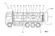
- Fig. 1 shows a simplified side view of a commercial vehicle with a tarpaulin structure, which in particular has a plurality of side tarpaulins and a roof-top, and a plurality of housed in brackets tarpaulins.
- Like reference numerals designate like parts.
- a commercial vehicle 10 includes, inter alia, a commercial vehicle body 12 comprising a tarpaulin structure with a plurality of stakes, of which only four stanchions 14 to 20 or stakes can be seen.
- the commercial vehicle 10 may be a truck, a trailer, a trailer, etc.
- load securing elements such as For example, lashing straps, lashing, lashing, lashing straps, straps and Zurrlatten the better graphical overview are not shown.
- the better graphic overview half also not shown longitudinal and transverse bars and tarpaulins are fixed, on which a tarpaulin 26 rests.
- the commercial vehicle body 12 or the tarpaulin structure is equipped with a tarpaulin board arrangement 28 according to the invention.
- the tarp board assembly 28 includes, among other things, a plurality of tarpaulin boards, of which only two tarpaulins 30,32 carry a reference numeral. Between the front stanchion 14 and the rear stanchion 20 as well as the respectively underlying, invisible stanchions, perpendicular to the plane of the drawing are more, but not shown, tarpaulin boards. Among other things, the tarpaulin boards serve to secure the position of the load 24 and as a lateral support for the tarpaulin 26.
- the tarpaulin board 30 is received in two brackets 34,36 between the adjacent stanchions 16,18, while the tarpaulin board 32 is received in two brackets 38,40 between the two adjacent stanchions 18 and 20.
- the structural design of the other, not provided with reference numerals or hidden mounts corresponds to each of the brackets 34 to 40th
- the tarpaulin assembly 28 together with the tarpaulins tubes, the longitudinal and transverse spars, the posts or posts and possibly other components, not shown, a frame 42 for the tarpaulin 26, wherein the frame 42 and the tarpaulin 26 a tarpaulin structure 44 of the commercial vehicle body 12th embody.
- the tarpaulin structure 44 is preferably designed as a side sliding tarp structure with sliding roof.
- a loading space 46 for receiving the load is defined on all sides by the tarpaulin structure 44 and the loading area 22.
- the brackets 34 to 38 are configured according to a first embodiment, while the holder 40 is deviating from this in accordance with a second embodiment variant is executed.
- two brackets 34,36 according to the first embodiment must be provided for one tarpaulin board.
- a tarp board 32 can also be accommodated in a holder 38 in accordance with the first embodiment variant and in a further holder 40 according to the second embodiment variant.
- the inclusion of tarpaulin boards in two brackets according to the second embodiment is not provided, since in such a constellation insertion of the tarpaulin boards would not or only with great difficulty possible.
- the brackets 34 to 40 are designed in such a way that the tarpaulin boards 30, 32 are in each case received in a form-fitting manner and thus non-positively, whereby mechanical forces, in particular substantially parallel to the loading surface 22 - i.e. engage parallel to the longitudinal and / or transverse axis of the utility vehicle 10 - regardless of the mechanical strength of the tarpaulin 26 are reliably received.
- This significantly reducible material thickness of the tarpaulin 26 leads to a higher flexibility and at the same time a lower weight of the entire commercial vehicle body 12, from which the effect of a payload increase or fuel saving can result.
- the tarpaulin assembly 28 is preferably designed as a kit that allows easy and quick retrofitting of existing commercial vehicle bodies 12 of commercial vehicles 10 of all kinds with the tarpaulin boards and the associated brackets.
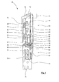
- the Fig. 2 shows a partial perspective view of the first embodiment of a holder for a tarpaulin board with a pocket and a pin angle.
- the holder 34 includes a pocket 50 and a pivot angle 52, which are preferably formed as separate sheet metal shaped parts.
- the pocket 50 and the pin 52 are - for example by folding of blanks - made of steel, alloys, especially high-strength alloys, or plastics, especially high-strength plastics formed. This manufacturing process ensures a cost-effective production of the holder 34 in large quantities with a high dimensional accuracy at the same time.
- the pocket 50 and the pivot angle 52 may also be formed with a fiber composite plastic.
- the pocket 50 has an approximately rectangular rear wall 54, to which side walls 56,58 connect at both sides at a right angle.
- the likewise approximately rectangular side walls 56,58 are formed substantially parallel spaced from each other.
- An inner distance 60 between the side walls 56, 58 is dimensioned such that, for example, one of the tarpaulin boards 30, 32 can preferably be inserted into the pocket 50 with a slight clearance fit.
- a bottom tab 62, 64 is formed, which each assign to one another and which in each case enclose a right angle with the side walls 56, 58.
- the bottom flaps 62, 64 may be joined together in the region of the gap 66 by a joining seam, in particular a welded seam or glued seam, between the two bottom flaps 62, 64.
- a joining seam in particular a welded seam or glued seam
- unspecified rear edges of the bottom flaps 62, 64 may be connected to the rear wall 54, in particular welded thereto.
- the cargo-side side wall 56 has in a particular embodiment, two holes 68 of larger diameter, which serve the simple visual verification of the proper fit of an inserted into the pocket 50 tarpaulin board.
- both bottom flaps 62,64 is also each a hidden here, approximately semicircular recess. These recesses are each formed a mirror image of each other and together form an approximately circular recess for the implementation of a pin of the pin angle 52nd
- a plurality of holes and / or slots is introduced, which are not provided with reference numerals and in the fasteners 70, in particular rivets or bolt connections, can be introduced, with which the bag 50 is attached here by way of example to the stanchion 16.
- the stanchion 16 or the post of the commercial vehicle body also has a multiplicity of unnamed bores and / or oblong holes.
- An outer edge 72 of the rear wall 54 is formed obliquely in a particular embodiment, so that an unnamed height of the cargo-side side wall 56 is smaller than a likewise not designated height of the plane-side side wall 58.
- a resulting height difference 74 between the side walls 56, 58 may correspond, for example, to the inner spacing 60 between the side walls 56, 58.
- the journal angle 52 has an approximately rectangular back flange 76.
- An approximately triangular node wall 78 connects to the back flange 76 at a right angle.
- the node wall 78 merges at a right angle into a rectangular support flange 80.
- the support flange 80 has an unspecified recess or bore in which a pin 82 is attached.
- the attachment of the pin 82 is preferably carried out by means of an annular weld 84.
- the pin 82 may also be pressed into the support flange 80, glued to be caulked or screwed with this.
- the pin 82 includes a cylindrical portion 86, followed by a truncated cone portion 88 connects, which merges into a tip portion 90.
- the back flange 76 and the node wall 78 are each provided with a plurality of holes and / or slots that allow the setting of the pivot angle 52 on the stanchion 16 by means of the fasteners 70.
- a rear flange edge 92 can be connected to a rear flange edge 94, in particular by means of a caterpillar-shaped weld 96, joined together.
- the pocket 50 and the pivot angle 52 of the holder 34 are connected only indirectly via the stanchion 16, but may also be joined together if necessary.
- the pin 82 in conjunction with a correspondingly formed bore in an end portion of a tarpaulin board a positive and non-positive fixing of the end portion of the tarpaulin board formed in the pin 52 and the pocket 50 holder 34.
- a second end portion of the tarpaulin board is in a mirror image to Holder 34 formed, not shown here holder also received positively and non-positively.
- a tarpaulin board substantially all parallel to the loading area or parallel to the longitudinal and / or transverse axis of the commercial vehicle attacking mechanical forces transmitted largely independent of the mechanical nature of the tarpaulin of the top of the commercial vehicle body.
- a tarpaulin board received or inserted in the pocket 50 can only lift off the journal 82 parallel to an unnamed longitudinal axis of the journal 82 or to the vertical axis of the commercial vehicle.
- Even in the case of a greater deflection of the tarpaulin board 30 due to high shear forces prevent the pins 82 of the brackets 34 reliably slipping out of the tarpaulin board from the opposite and facing each other pockets of the brackets.
- the tip portion 90 has a small radius of curvature and / or is formed with a high hardness material and / or is self-hardened so that a spatial location of the pin 82 can be grained with high accuracy, for example, with respect to a retractable tarp board.
- a tarpaulin board assembled in the simplest way on site, that is in particular cut to length and drilled end so that it can be inserted very precisely in the attaching to the stanchions brackets 34. Consequently, the tarpaulin assembly (kit) for easy retrofitting of existing commercial vehicle bodies is suitable.
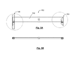
- the Fig. 3 shows an isometric view of an embodiment of a tarpaulin board.
- the tarp board 30 is formed with an extruded rectangular hollow profile made of an aluminum alloy. Deviating from this, the tarpaulin board 30 may have a quadrangular, a slightly oval or another cross-sectional geometry.
- a cylindrical bore 104, 106 is introduced in each case, in which the pins 82 of the pin 52 (see in particular FIG. Fig. 2 ) are at least partially positively received.
- Both longitudinal sides 108,110 of the tarpaulin board 30 have a reduced material thickness compared to the narrow sides 112,114.
- a wall thickness 116 of the narrow sides 112, 114 is, for example, at least 3 mm, while a wall thickness 118 of the longitudinal sides 108, 110 is, for example, at least 2 mm. Due to the higher wall thickness 116 in the region of the narrow sides 112,114, the tarpaulin boards achieve a high resistance to forces acting in particular transversely to the longitudinal axis of the vehicle, as can occur, for example, in the case of accidental centrifugal movements.
- a height 120 of the longitudinal sides 108,110 is significantly larger than a width 122 of the narrow sides 112,114, among other things, to create an enlarged support surface for the tarpaulin. In the illustrated embodiment of the Fig.
- the length 120 is dimensioned about four times as large as the width 122.
- a length 124 of the tarpaulin board 30 is dimensioned or adaptable by appropriately cutting a tarpaulin board with a standard length, that this between two adjacent stanchions with the respective holders attached to it in the ideal case free of play is recordable.
- the initially undrilled tarpaulins have a standardized excess length. This makes it possible to use the tarpaulin arrangement even in commercial vehicle buildings with different spacing between rungs.
- a number of brackets corresponding to the number of required tarpaulins is attached to the stanchions.
- the tarpaulin boards are cut to length so far by sawing that they are in two, attached to adjacent stanchions and in the associated, facing each other mounts as free of play inserted. If a tarp board has the proper length, it can be placed on the pins in the two associated brackets.
- the two holes to be provided in the end sections can be introduced with high accuracy in a final assembly step.
- all brackets and tarpaulin boards are moved until the tarpaulin assembly is fully integrated with the commercial vehicle body.
- the tarpaulin boards or the tarpaulin battens or tarpaulins (hollow) profiles may also be formed with wood, the end sections preferably being provided with metallic end fittings in order to prevent the pins from tearing out of the bores at higher mechanical loads.
- the end fittings are preferably designed such that they can be permanently applied to the end sections of the wooden tarpaulin board on site using standard tools, for example a hammer or the like.
- the tarpaulin boards can also be formed with fiber reinforced plastics in order to achieve a further reduction in weight with a simultaneous increase in strength. Even in such a constellation metallic Endbehave can be provided in each case on both end portions of the tarpaulin boards.
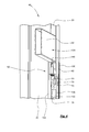
- the Fig. 4 shows a partial perspective view of a second embodiment of a holder with a U-profile and a pin angle with a tarpaulin board.
- the drawn here board 32 corresponds to the structural design of the tarpaulin board 30 (see especially the Fig. 1 . 3 ).
- the holder 40 is constructed with a continuous U-profile 130 and a U-rail using only one pin angle 52.
- the U-profile 130 has a rear wall 132 and two side walls 134,136 and is preferably made of steel or aluminum in the extrusion process. Alternatively or additionally, the U-profile 130 may also be formed with a fiber composite plastic and / or with wood.
- the U-profile 130 preferably extends over an entire length of the stanchion 20 and is secured thereto by means not shown fasteners, such as rivets or bolt connections.
- fasteners such as rivets or bolt connections.
- a plurality of bores and / or elongated holes for receiving the fastening elements are provided in the rear wall 132 of the U-profile 130 and in the stanchion 20.
- the attachment in the U-profile 130 via unspecified holes and / or slots in the node wall 78 of the pivot angle 52 and the plane-side side wall 136 of the U-profile 130 using the fasteners 70.
- the back flange 76 of Pin angle 52 are fastened by means not shown fastening elements in addition to the rear wall 132 of the U-profile 130.
- the back flange 76 of the pin angle 52 has a plurality of unnamed holes.
- an end portion 138 of the tarpaulin board 32 shown here by way of example can preferably be inserted or accommodated with a slight clearance fit.
- the U-profile 130 is a reliable position assurance of the tarpaulin board 32 against forces that act in particular parallel to the transverse axis of the commercial vehicle, guaranteed.
- bore 140 of the pin 82 of the pin angle 52 at least partially positively insertable.
- the pockets, U-profiles and / or journal angles described herein are advantageously connected to the stakes by means of rivets and / or bolt connections.
- the pockets, U-profiles and / or pin angle are attached to the stanchions in alternative embodiments by means of welded joints.
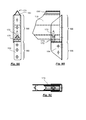
- Fig. 5A shows a further embodiment of a tarp board assembly 150 in a side view
- Fig. 5B the tarp board arrangement according to Fig. 5A in a view from above.
- a tarp board 152 is disposed at the right-hand end in a tarpaulin pocket 154, while a left-hand end of the tarpaulin board 152 is disposed in a tarpaulin U-profile 156.
- the right- and left-sided arrangements can also be formed identically or reversed.
- Fig. 6A shows the left-side end of the tarpaulin board 152 according to Fig. 5A in the tarpaulin U-profile on an enlarged scale.
- Fig. 6B shows the in Fig. 6A shown area in a view from the left side while Fig. 6C the range of Fig. 6A in a view from above.
- B and C carries a U-profile 158 a pin angle 160, which in turn carries a pin 162.
- the tarpaulin board 152 rests on a support flange 164 of the journal angle 160, preferably with the interposition of a rubber plate 163, wherein the journal 162 projects through a recess in the tarpaulin board 152.
- the tarpaulin U-profile 156 either forms a stanchion or is attached to a stanchion.
- Fig. 7A , B and C show the right-hand area of the tarpaulin assembly 150 according to FIG Fig. 5A in an enlarged section.
- Fig. 7A shows the planeboard pocket 154 in a view from the right side while Fig. 7B this tarpaulin pocket 154 in a frontal view and Fig. 7C in a view from above.
- the tarp board pocket 154 has an upper portion 166 having a U-shaped profile and a lower portion 168 having an L-shaped profile.
- a support flange 170 is attached, in particular welded, which carries a pin 172.
- the support flange 170 serves - preferably with the interposition of a rubber plate 173 - as a support for the tarpaulin board 152, wherein the pin 172 penetrates through a corresponding recess in the tarpaulin board.
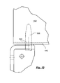
- Fig. 8A , B and C substantially correspond to the embodiment according to Fig. 6A
- the tarpaulin board 174 deviates from the tarpaulin board 152.
- the tarpaulin board 174 has on its lower narrow side 176 a bead 178, such that there is a roof-like structure in the lower region of the tarpaulin board.
- a hole 180 for receiving the pin 162 is provided. This hole has a larger margin than a hole in a flat surface.
- the contact surface of the pin on the lower narrow side 176 of the tarpaulin board 174 is larger, so that at an axial tensile stress of the tarpaulin board 174 lower deformation forces acting on the material of the tarpaulin board 174, so that the Auflauf für the material of the tarpaulin board on the pin 162th is reduced.
- the tarpaulin board 174 tolerates higher tensile loads due to this particular embodiment.
- the wall thickness of the tarpaulin hollow profile may also be made thinner due to this property than in the case of the tarpaulin board 152 according to FIG Fig. 6A , B and C.
- Fig. 9A , B and C substantially corresponds to the embodiment according to Fig. 7A B and C, however, with a tarp board 174, as related to Fig. 8A , B and C has been described.
- the tarpaulin board 174 has not only in the region of the lower narrow side 176 a bead 178, but also in the region of the upper narrow side 182 a roof-like contour 184.
- This roof-like contour 184 corresponds to the contour of the bead 178, so that an engagement of the roof-like contour 184 in the contour of the bead 178 is made possible.
- a plurality of such tarpaulins boards 174 are stacked in a gripping the respective ends U-profile, so high stabilities and also a rain protection can be achieved without additional tarpaulin.
- the bead 178 can be introduced into a bottom-side bar, whereby high lateral forces, for example by slipping cargo, can be absorbed.
- Fig. 10 shows a particular embodiment of a pin 186 which engages in a tarpaulin board, for example according to 152.
- This pin 186 has a bead 188, which forms a recess in the region of the pin 186, in which a lower narrow side 190 of the tarpaulin board can engage.
- This bead 188 may be provided either tangentially circumferentially on the pin 186 or only partially circumferential.
- the beading 188 contributes to an entanglement of the tarpaulin board 152 with the pin 186 when the tarpaulin board 152 is loaded axially, as a result of which the overall stability of the commercial vehicle body 12 is increased.
Landscapes
- Engineering & Computer Science (AREA)
- Chemical & Material Sciences (AREA)
- Combustion & Propulsion (AREA)
- Transportation (AREA)
- Mechanical Engineering (AREA)
- Tents Or Canopies (AREA)
- Vehicle Step Arrangements And Article Storage (AREA)
Applications Claiming Priority (1)
| Application Number | Priority Date | Filing Date | Title |
|---|---|---|---|
| DE202012101206U DE202012101206U1 (de) | 2012-04-03 | 2012-04-03 | Planenbrettanordnung, Nutzfahrzeugaufbau und Nutzfahrzeug |
Publications (3)
| Publication Number | Publication Date |
|---|---|
| EP2647555A2 true EP2647555A2 (fr) | 2013-10-09 |
| EP2647555A3 EP2647555A3 (fr) | 2015-10-21 |
| EP2647555B1 EP2647555B1 (fr) | 2017-12-13 |
Family
ID=46511126
Family Applications (1)
| Application Number | Title | Priority Date | Filing Date |
|---|---|---|---|
| EP13162104.7A Not-in-force EP2647555B1 (fr) | 2012-04-03 | 2013-04-03 | Assemblage d'une planche de ridelle , superstructure volume de chargement et véhicule utilitaire |
Country Status (2)
| Country | Link |
|---|---|
| EP (1) | EP2647555B1 (fr) |
| DE (1) | DE202012101206U1 (fr) |
Citations (3)
| Publication number | Priority date | Publication date | Assignee | Title |
|---|---|---|---|---|
| DE10238755A1 (de) | 2002-03-26 | 2003-10-16 | Bosch Gmbh Robert | Antriebsschlupfregelung mit Sollschlupf-Anpassung |
| DE10238785A1 (de) | 2002-08-23 | 2004-03-11 | Sommer-Fahrzeugbau Gmbh & Co | Aufbau für Lastfahrzeuge |
| DE202008012725U1 (de) | 2008-09-24 | 2008-11-27 | Rs-Kunststoffgesellschaft Mbh | Lattentasche |
Family Cites Families (8)
| Publication number | Priority date | Publication date | Assignee | Title |
|---|---|---|---|---|
| US4025211A (en) * | 1976-04-02 | 1977-05-24 | Gump William E | Draw-tight connector |
| DE2728450C2 (de) * | 1977-06-24 | 1986-04-30 | Wackenhut, Ernst, 7270 Nagold | Plangestell, insbesondere für Lkw |
| US4986513A (en) * | 1990-05-07 | 1991-01-22 | Harbor Towne Fence, Inc. | Fence connector assembly |
| ES1035193Y (es) * | 1996-09-26 | 1997-08-01 | Adaico Sl | Poste perfeccionado, para cartolas de camiones. |
| DE202007001329U1 (de) * | 2007-01-30 | 2008-06-05 | Kaiser, Ria | Ladungssicherungslattensystem für eine Fahrzeug-, anhänger- oder -aufliegerwand |
| DE102007037294B4 (de) * | 2007-08-07 | 2014-04-03 | Kögel Trailer GmbH & Co. KG | Vorrichtung zur Ladungssicherung bei Nutzfahrzeugen sowie Nutzfahrzeug mit einer derartigen Vorrichtung |
| DE102008025440B4 (de) * | 2008-05-27 | 2021-08-12 | Spanset Inter Ag | Einstecklatte für einen Aufbau eines Transportfahrzeugs, Aufbau für die Ladefläche eines Transportfahrzeugs, eines Lastkraftwagens, eines Aufliegers oder Anhängers für einen Lastkraftwagen mit einer solchen Einstecklatte und Transportfahrzeug, Lastkraftwagen, Auflieger oder Anhänger für einen Lastkraftwagen mit einer Ladefläche und einem solchen Aufbau. |
| ES2388796T5 (es) * | 2008-11-10 | 2017-03-16 | F. Hesterberg & Söhne Gmbh & Co. Kg | Soporte de listones para superestructuras de vehículos industriales |
-
2012
- 2012-04-03 DE DE202012101206U patent/DE202012101206U1/de not_active Expired - Lifetime
-
2013
- 2013-04-03 EP EP13162104.7A patent/EP2647555B1/fr not_active Not-in-force
Patent Citations (3)
| Publication number | Priority date | Publication date | Assignee | Title |
|---|---|---|---|---|
| DE10238755A1 (de) | 2002-03-26 | 2003-10-16 | Bosch Gmbh Robert | Antriebsschlupfregelung mit Sollschlupf-Anpassung |
| DE10238785A1 (de) | 2002-08-23 | 2004-03-11 | Sommer-Fahrzeugbau Gmbh & Co | Aufbau für Lastfahrzeuge |
| DE202008012725U1 (de) | 2008-09-24 | 2008-11-27 | Rs-Kunststoffgesellschaft Mbh | Lattentasche |
Also Published As
| Publication number | Publication date |
|---|---|
| EP2647555B1 (fr) | 2017-12-13 |
| EP2647555A3 (fr) | 2015-10-21 |
| DE202012101206U1 (de) | 2012-06-05 |
Similar Documents
| Publication | Publication Date | Title |
|---|---|---|
| DE102010036450B4 (de) | B-Säulenverstärkung eines Kraftfahrzeugs | |
| DE102016000605A1 (de) | Kraftfahrzeugheck | |
| DE102009012057B4 (de) | Vorrichtung zum Aufnehmen von Seitenkräften und Kraftfahrzeug mit einer derartigen Vorrichtung | |
| EP3165426A1 (fr) | Ensemble pour un véhicule comprenant un châssis secondaire et une structure d'absorption de chocs | |
| DE10232841A1 (de) | Bodenträgeranordnung an Kraftfahrzeugen | |
| DE102016004577B4 (de) | Tragrahmenstruktur zum Befestigen wenigstens eines Energiespeichers an einem Kraftfahrzeugrohbau | |
| DE102010002789A1 (de) | Säulenstruktur eines Fahrzeugaufbaus | |
| EP2394834A2 (fr) | Support de collision de porte | |
| DE102007032245A1 (de) | Kraftfahrzeugkarosserie mit seitlichen Schwellern | |
| DE102007032244A1 (de) | Kraftfahrzeugkarosserie mit seitlichen Schwellern | |
| DE102018100701A1 (de) | Dachrahmen mit einer Strebe zum Verstärken gewölbter Elemente | |
| DE102013001668B4 (de) | Karosseriestruktur eines Kraftfahrzeugs und Kraftfahrzeug mit einer derartigen Karosseriestruktur | |
| DE102021128850B4 (de) | Stoßfängerquerträger mit lokaler Deformationszone | |
| DE10232842A1 (de) | Bodenversteifungsstruktur an Kraftfahrzeugen | |
| DE102008009088B4 (de) | Karosserie eines Kraftfahrzeugs mit einem Seitenschweller | |
| EP3192723B1 (fr) | Système de châssis auxiliaire destiné à l'amélioration de la sécurité en cas d'accident | |
| DE102007032246B4 (de) | Kraftfahrzeugkarosserie mit seitlichen Schwellern | |
| EP2420406A1 (fr) | Dispositif de sécurisation d'un chargement sur la surface de chargement d'un montage de véhicule | |
| DE102015012262B4 (de) | Tür für einen Kraftwagen | |
| DE102005050959A1 (de) | Crashbox am Türschweller eines Kraftfahrzeugs | |
| EP2647555B1 (fr) | Assemblage d'une planche de ridelle , superstructure volume de chargement et véhicule utilitaire | |
| DE102015204917A1 (de) | Seitentür für ein Fahrzeug sowie Fahrzeug mit einer derartigen Seitentür | |
| DE102009012237B4 (de) | Karosserie für ein Kraftfahrzeug | |
| DE102013000637B4 (de) | Karosseriestruktur für ein Fahrzeug | |
| DE102012009415B4 (de) | Fahrzeugkarosserie mit einer ein crashaktives Stützelement aufweisenden Fahrzeugtüre |
Legal Events
| Date | Code | Title | Description |
|---|---|---|---|
| PUAI | Public reference made under article 153(3) epc to a published international application that has entered the european phase |
Free format text: ORIGINAL CODE: 0009012 |
|
| AK | Designated contracting states |
Kind code of ref document: A2 Designated state(s): AL AT BE BG CH CY CZ DE DK EE ES FI FR GB GR HR HU IE IS IT LI LT LU LV MC MK MT NL NO PL PT RO RS SE SI SK SM TR |
|
| AX | Request for extension of the european patent |
Extension state: BA ME |
|
| PUAL | Search report despatched |
Free format text: ORIGINAL CODE: 0009013 |
|
| AK | Designated contracting states |
Kind code of ref document: A3 Designated state(s): AL AT BE BG CH CY CZ DE DK EE ES FI FR GB GR HR HU IE IS IT LI LT LU LV MC MK MT NL NO PL PT RO RS SE SI SK SM TR |
|
| AX | Request for extension of the european patent |
Extension state: BA ME |
|
| RIC1 | Information provided on ipc code assigned before grant |
Ipc: B62D 33/02 20060101AFI20150914BHEP |
|
| 17P | Request for examination filed |
Effective date: 20160415 |
|
| RBV | Designated contracting states (corrected) |
Designated state(s): AL AT BE BG CH CY CZ DE DK EE ES FI FR GB GR HR HU IE IS IT LI LT LU LV MC MK MT NL NO PL PT RO RS SE SI SK SM TR |
|
| GRAP | Despatch of communication of intention to grant a patent |
Free format text: ORIGINAL CODE: EPIDOSNIGR1 |
|
| INTG | Intention to grant announced |
Effective date: 20170703 |
|
| GRAS | Grant fee paid |
Free format text: ORIGINAL CODE: EPIDOSNIGR3 |
|
| GRAA | (expected) grant |
Free format text: ORIGINAL CODE: 0009210 |
|
| AK | Designated contracting states |
Kind code of ref document: B1 Designated state(s): AL AT BE BG CH CY CZ DE DK EE ES FI FR GB GR HR HU IE IS IT LI LT LU LV MC MK MT NL NO PL PT RO RS SE SI SK SM TR |
|
| REG | Reference to a national code |
Ref country code: GB Ref legal event code: FG4D Free format text: NOT ENGLISH |
|
| REG | Reference to a national code |
Ref country code: AT Ref legal event code: REF Ref document number: 954080 Country of ref document: AT Kind code of ref document: T Effective date: 20171215 Ref country code: CH Ref legal event code: EP |
|
| REG | Reference to a national code |
Ref country code: IE Ref legal event code: FG4D Free format text: LANGUAGE OF EP DOCUMENT: GERMAN |
|
| REG | Reference to a national code |
Ref country code: DE Ref legal event code: R096 Ref document number: 502013008993 Country of ref document: DE |
|
| REG | Reference to a national code |
Ref country code: NL Ref legal event code: MP Effective date: 20171213 |
|
| REG | Reference to a national code |
Ref country code: LT Ref legal event code: MG4D |
|
| REG | Reference to a national code |
Ref country code: DE Ref legal event code: R082 Ref document number: 502013008993 Country of ref document: DE Representative=s name: JABBUSCH SIEKMANN & WASILJEFF, DE Ref country code: DE Ref legal event code: R081 Ref document number: 502013008993 Country of ref document: DE Owner name: HOFMEISTER & MEINCKE GMBH, DE Free format text: FORMER OWNER: HOFMEISTER & MEINCKE GMBH & CO. KG, 28279 BREMEN, DE |
|
| PG25 | Lapsed in a contracting state [announced via postgrant information from national office to epo] |
Ref country code: LT Free format text: LAPSE BECAUSE OF FAILURE TO SUBMIT A TRANSLATION OF THE DESCRIPTION OR TO PAY THE FEE WITHIN THE PRESCRIBED TIME-LIMIT Effective date: 20171213 Ref country code: SE Free format text: LAPSE BECAUSE OF FAILURE TO SUBMIT A TRANSLATION OF THE DESCRIPTION OR TO PAY THE FEE WITHIN THE PRESCRIBED TIME-LIMIT Effective date: 20171213 Ref country code: FI Free format text: LAPSE BECAUSE OF FAILURE TO SUBMIT A TRANSLATION OF THE DESCRIPTION OR TO PAY THE FEE WITHIN THE PRESCRIBED TIME-LIMIT Effective date: 20171213 Ref country code: NO Free format text: LAPSE BECAUSE OF FAILURE TO SUBMIT A TRANSLATION OF THE DESCRIPTION OR TO PAY THE FEE WITHIN THE PRESCRIBED TIME-LIMIT Effective date: 20180313 |
|
| PG25 | Lapsed in a contracting state [announced via postgrant information from national office to epo] |
Ref country code: GR Free format text: LAPSE BECAUSE OF FAILURE TO SUBMIT A TRANSLATION OF THE DESCRIPTION OR TO PAY THE FEE WITHIN THE PRESCRIBED TIME-LIMIT Effective date: 20180314 Ref country code: BG Free format text: LAPSE BECAUSE OF FAILURE TO SUBMIT A TRANSLATION OF THE DESCRIPTION OR TO PAY THE FEE WITHIN THE PRESCRIBED TIME-LIMIT Effective date: 20180313 Ref country code: RS Free format text: LAPSE BECAUSE OF FAILURE TO SUBMIT A TRANSLATION OF THE DESCRIPTION OR TO PAY THE FEE WITHIN THE PRESCRIBED TIME-LIMIT Effective date: 20171213 Ref country code: LV Free format text: LAPSE BECAUSE OF FAILURE TO SUBMIT A TRANSLATION OF THE DESCRIPTION OR TO PAY THE FEE WITHIN THE PRESCRIBED TIME-LIMIT Effective date: 20171213 Ref country code: HR Free format text: LAPSE BECAUSE OF FAILURE TO SUBMIT A TRANSLATION OF THE DESCRIPTION OR TO PAY THE FEE WITHIN THE PRESCRIBED TIME-LIMIT Effective date: 20171213 |
|
| PG25 | Lapsed in a contracting state [announced via postgrant information from national office to epo] |
Ref country code: NL Free format text: LAPSE BECAUSE OF FAILURE TO SUBMIT A TRANSLATION OF THE DESCRIPTION OR TO PAY THE FEE WITHIN THE PRESCRIBED TIME-LIMIT Effective date: 20171213 |
|
| PG25 | Lapsed in a contracting state [announced via postgrant information from national office to epo] |
Ref country code: EE Free format text: LAPSE BECAUSE OF FAILURE TO SUBMIT A TRANSLATION OF THE DESCRIPTION OR TO PAY THE FEE WITHIN THE PRESCRIBED TIME-LIMIT Effective date: 20171213 Ref country code: CY Free format text: LAPSE BECAUSE OF FAILURE TO SUBMIT A TRANSLATION OF THE DESCRIPTION OR TO PAY THE FEE WITHIN THE PRESCRIBED TIME-LIMIT Effective date: 20171213 Ref country code: ES Free format text: LAPSE BECAUSE OF FAILURE TO SUBMIT A TRANSLATION OF THE DESCRIPTION OR TO PAY THE FEE WITHIN THE PRESCRIBED TIME-LIMIT Effective date: 20171213 Ref country code: CZ Free format text: LAPSE BECAUSE OF FAILURE TO SUBMIT A TRANSLATION OF THE DESCRIPTION OR TO PAY THE FEE WITHIN THE PRESCRIBED TIME-LIMIT Effective date: 20171213 Ref country code: SK Free format text: LAPSE BECAUSE OF FAILURE TO SUBMIT A TRANSLATION OF THE DESCRIPTION OR TO PAY THE FEE WITHIN THE PRESCRIBED TIME-LIMIT Effective date: 20171213 |
|
| PG25 | Lapsed in a contracting state [announced via postgrant information from national office to epo] |
Ref country code: PL Free format text: LAPSE BECAUSE OF FAILURE TO SUBMIT A TRANSLATION OF THE DESCRIPTION OR TO PAY THE FEE WITHIN THE PRESCRIBED TIME-LIMIT Effective date: 20171213 Ref country code: RO Free format text: LAPSE BECAUSE OF FAILURE TO SUBMIT A TRANSLATION OF THE DESCRIPTION OR TO PAY THE FEE WITHIN THE PRESCRIBED TIME-LIMIT Effective date: 20171213 Ref country code: IT Free format text: LAPSE BECAUSE OF FAILURE TO SUBMIT A TRANSLATION OF THE DESCRIPTION OR TO PAY THE FEE WITHIN THE PRESCRIBED TIME-LIMIT Effective date: 20171213 Ref country code: IS Free format text: LAPSE BECAUSE OF FAILURE TO SUBMIT A TRANSLATION OF THE DESCRIPTION OR TO PAY THE FEE WITHIN THE PRESCRIBED TIME-LIMIT Effective date: 20180413 Ref country code: SM Free format text: LAPSE BECAUSE OF FAILURE TO SUBMIT A TRANSLATION OF THE DESCRIPTION OR TO PAY THE FEE WITHIN THE PRESCRIBED TIME-LIMIT Effective date: 20171213 |
|
| REG | Reference to a national code |
Ref country code: DE Ref legal event code: R097 Ref document number: 502013008993 Country of ref document: DE |
|
| PG25 | Lapsed in a contracting state [announced via postgrant information from national office to epo] |
Ref country code: MT Free format text: LAPSE BECAUSE OF FAILURE TO SUBMIT A TRANSLATION OF THE DESCRIPTION OR TO PAY THE FEE WITHIN THE PRESCRIBED TIME-LIMIT Effective date: 20171213 |
|
| PLBE | No opposition filed within time limit |
Free format text: ORIGINAL CODE: 0009261 |
|
| STAA | Information on the status of an ep patent application or granted ep patent |
Free format text: STATUS: NO OPPOSITION FILED WITHIN TIME LIMIT |
|
| 26N | No opposition filed |
Effective date: 20180914 |
|
| PG25 | Lapsed in a contracting state [announced via postgrant information from national office to epo] |
Ref country code: DK Free format text: LAPSE BECAUSE OF FAILURE TO SUBMIT A TRANSLATION OF THE DESCRIPTION OR TO PAY THE FEE WITHIN THE PRESCRIBED TIME-LIMIT Effective date: 20171213 Ref country code: MC Free format text: LAPSE BECAUSE OF FAILURE TO SUBMIT A TRANSLATION OF THE DESCRIPTION OR TO PAY THE FEE WITHIN THE PRESCRIBED TIME-LIMIT Effective date: 20171213 |
|
| REG | Reference to a national code |
Ref country code: CH Ref legal event code: PL |
|
| REG | Reference to a national code |
Ref country code: BE Ref legal event code: MM Effective date: 20180430 |
|
| GBPC | Gb: european patent ceased through non-payment of renewal fee |
Effective date: 20180403 |
|
| REG | Reference to a national code |
Ref country code: IE Ref legal event code: MM4A |
|
| PG25 | Lapsed in a contracting state [announced via postgrant information from national office to epo] |
Ref country code: LU Free format text: LAPSE BECAUSE OF NON-PAYMENT OF DUE FEES Effective date: 20180403 |
|
| PG25 | Lapsed in a contracting state [announced via postgrant information from national office to epo] |
Ref country code: CH Free format text: LAPSE BECAUSE OF NON-PAYMENT OF DUE FEES Effective date: 20180430 Ref country code: LI Free format text: LAPSE BECAUSE OF NON-PAYMENT OF DUE FEES Effective date: 20180430 Ref country code: GB Free format text: LAPSE BECAUSE OF NON-PAYMENT OF DUE FEES Effective date: 20180403 Ref country code: BE Free format text: LAPSE BECAUSE OF NON-PAYMENT OF DUE FEES Effective date: 20180430 Ref country code: SI Free format text: LAPSE BECAUSE OF FAILURE TO SUBMIT A TRANSLATION OF THE DESCRIPTION OR TO PAY THE FEE WITHIN THE PRESCRIBED TIME-LIMIT Effective date: 20171213 |
|
| PG25 | Lapsed in a contracting state [announced via postgrant information from national office to epo] |
Ref country code: FR Free format text: LAPSE BECAUSE OF NON-PAYMENT OF DUE FEES Effective date: 20180430 Ref country code: IE Free format text: LAPSE BECAUSE OF NON-PAYMENT OF DUE FEES Effective date: 20180403 |
|
| REG | Reference to a national code |
Ref country code: AT Ref legal event code: MM01 Ref document number: 954080 Country of ref document: AT Kind code of ref document: T Effective date: 20180403 |
|
| PG25 | Lapsed in a contracting state [announced via postgrant information from national office to epo] |
Ref country code: AT Free format text: LAPSE BECAUSE OF NON-PAYMENT OF DUE FEES Effective date: 20180403 |
|
| PG25 | Lapsed in a contracting state [announced via postgrant information from national office to epo] |
Ref country code: TR Free format text: LAPSE BECAUSE OF FAILURE TO SUBMIT A TRANSLATION OF THE DESCRIPTION OR TO PAY THE FEE WITHIN THE PRESCRIBED TIME-LIMIT Effective date: 20171213 |
|
| PG25 | Lapsed in a contracting state [announced via postgrant information from national office to epo] |
Ref country code: HU Free format text: LAPSE BECAUSE OF FAILURE TO SUBMIT A TRANSLATION OF THE DESCRIPTION OR TO PAY THE FEE WITHIN THE PRESCRIBED TIME-LIMIT; INVALID AB INITIO Effective date: 20130403 Ref country code: PT Free format text: LAPSE BECAUSE OF FAILURE TO SUBMIT A TRANSLATION OF THE DESCRIPTION OR TO PAY THE FEE WITHIN THE PRESCRIBED TIME-LIMIT Effective date: 20171213 |
|
| PG25 | Lapsed in a contracting state [announced via postgrant information from national office to epo] |
Ref country code: MK Free format text: LAPSE BECAUSE OF NON-PAYMENT OF DUE FEES Effective date: 20171213 |
|
| PG25 | Lapsed in a contracting state [announced via postgrant information from national office to epo] |
Ref country code: AL Free format text: LAPSE BECAUSE OF FAILURE TO SUBMIT A TRANSLATION OF THE DESCRIPTION OR TO PAY THE FEE WITHIN THE PRESCRIBED TIME-LIMIT Effective date: 20171213 |
|
| P01 | Opt-out of the competence of the unified patent court (upc) registered |
Effective date: 20230516 |
|
| PGFP | Annual fee paid to national office [announced via postgrant information from national office to epo] |
Ref country code: DE Payment date: 20240417 Year of fee payment: 12 |
|
| REG | Reference to a national code |
Ref country code: DE Ref legal event code: R119 Ref document number: 502013008993 Country of ref document: DE |
|
| PG25 | Lapsed in a contracting state [announced via postgrant information from national office to epo] |
Ref country code: DE Free format text: LAPSE BECAUSE OF NON-PAYMENT OF DUE FEES Effective date: 20251104 |