EP2647583A1 - Tube de pincement extracteur de distribution avec piston interne - Google Patents
Tube de pincement extracteur de distribution avec piston interne Download PDFInfo
- Publication number
- EP2647583A1 EP2647583A1 EP12162955.4A EP12162955A EP2647583A1 EP 2647583 A1 EP2647583 A1 EP 2647583A1 EP 12162955 A EP12162955 A EP 12162955A EP 2647583 A1 EP2647583 A1 EP 2647583A1
- Authority
- EP
- European Patent Office
- Prior art keywords
- reservoir
- viscous liquid
- piston
- piston wedge
- dispensing device
- Prior art date
- Legal status (The legal status is an assumption and is not a legal conclusion. Google has not performed a legal analysis and makes no representation as to the accuracy of the status listed.)
- Withdrawn
Links
Images



Classifications
-
- B—PERFORMING OPERATIONS; TRANSPORTING
- B65—CONVEYING; PACKING; STORING; HANDLING THIN OR FILAMENTARY MATERIAL
- B65D—CONTAINERS FOR STORAGE OR TRANSPORT OF ARTICLES OR MATERIALS, e.g. BAGS, BARRELS, BOTTLES, BOXES, CANS, CARTONS, CRATES, DRUMS, JARS, TANKS, HOPPERS, FORWARDING CONTAINERS; ACCESSORIES, CLOSURES, OR FITTINGS THEREFOR; PACKAGING ELEMENTS; PACKAGES
- B65D35/00—Pliable tubular containers adapted to be permanently or temporarily deformed to expel contents, e.g. collapsible tubes for toothpaste or other plastic or semi-liquid material; Holders therefor
- B65D35/24—Pliable tubular containers adapted to be permanently or temporarily deformed to expel contents, e.g. collapsible tubes for toothpaste or other plastic or semi-liquid material; Holders therefor with auxiliary devices
- B65D35/28—Pliable tubular containers adapted to be permanently or temporarily deformed to expel contents, e.g. collapsible tubes for toothpaste or other plastic or semi-liquid material; Holders therefor with auxiliary devices for expelling contents
- B65D35/30—Pistons
Definitions
- This invention relates to disposable viscous liquid dispensing devices and, more particularly, to a new and improved device for extracting such viscous liquids as flowable candy or confectionery products, medicinal preparations and toothpaste from tubular reservoir containers.
- the suggested dome-shaped tube squeezer type of "add-on” will be understood to be pushed along the length of the tube from its sealed end towards the semi-rigid shoulder and nozzle.
- the maximum sliding range is only some 80-85% the length of the tube, besides being unable to flatten the spacing along its side edges.
- the alternatively utilized key-shaped squeezer "add-on” inserted over the sealed end of the tube and wound and rolled in an upwards fashion suffers the same problems as it approaches the rigid shoulder adjacent the nozzle's opening. Additionally, it exhibits the further disadvantages of frequently being lost, being unwieldy in use, and being unsightly in appearance due to the key's outward projection from the tube itself. The premature discarding of the tube container thus continues, and contributes to a greater accumulation of non-reusable trash.
- the present invention offers a new tube system employing an internal device to extract the product and reduce the amount of its contents otherwise left inside of the tube, as contrasted with the external "add-ons", which define the prior art.
- an internal piston here operates as a "wedge", sliding up all the way from the sealed end of the tube beyond its nozzle's shoulder and to the nozzle opening.
- the wall of the tube offers a resiliency to stretch over the rigid piston.
- the piston wedge will be seen to be utilized with the standard type of tubular reservoir container commonly employed.
- the piston wedge will be seen to be utilized in a new and different tubular reservoir container construction.
- the piston-wedge (or simply “piston"), constructed in accordance with the conventional cylindrical tube of FIGURES 2a-2d and with the alternative cylindrical tube configuration of FIGURES 4a-4f , is shown by reference numeral 10 in FIGURE 1a-1d .
- a head of the piston is shown at 12, and its size and shape conform with the diameter of the tube's nozzle orifice opening (shown at 18 in FIGURE 2b ). Such correspondency will allow all or most of the product/content of the tube 16 to be pushed by the piston out from the tube's nozzle 14 once inserted into the tube and moved forwardly along.
- FIGURE 1a A shoulder of the piston 10 is shown at 20 in FIGURE 1a , which bears against and is stopped by the semi-rigid shoulder of the tube shown at 22 in FIGURE 2b .
- Reference numeral 24 in FIGURE 1a identifies a series of rings (3 in FIGURE 1a ) slightly larger in diameter than the inside diameter of the tube 16 of FIGURES 2a-2d , typically fabricated of a soft plastic.
- the rings 24 are what allows the product content in the tube to only move forwardly and out the tube 16 through the nozzle orifice opening 18, and insures that virtually none of the product is left behind when pushing the piston forward by a pinching action.
- the first ring (the one closest to the head 12) pushes the product out of the orifice 18, possibly, however, leaving a small residual amount.
- the second ring serves as a back-up, and collects and pushes forward any residue that may have been left behind the first ring.
- the third ring (furthest from the head 12) operates the same way as the second ring to push forward any remaining residue. This dispenses or extracts a11 the product content confronted by the piston 10 in moving along internally of the tube. By having the rings 24 of larger diameter than the inside diameter of the tube, essentially no residue will collect at the inner wall of the tube.
- Reference numeral 26 in FIGURE 1a identifies a plurality of tracks or channels (3 in number) which allows the piston 10 to have a reduced surface and contact area. Having these tracks or channels allows a user to pinch the piston its forward movement with less force or drag than would otherwise be the case. As the tracks or channels 26 reduce the amount of contact area with the inner wall of the tube 16, they additionally allow the piston 10 to be hollow, as shown at 28 in the sectional view of FIGURE 1c . The result is a saving in plastic in the manufacture of the piston 10, and in reducing its overall weight.
- FIGURE 1a is a perspective top and front view of the piston 10
- FIGURE 1b is a perspective front view of the piston
- FIGURE 1c is a perspective front sectional view of the piston.
- FIGURE 1d represents a side view of the piston 10.
- the piston By having its tail end 30 "dome-shaped", the piston is allowed to move forwardly along the tube 16 towards the nozzle 14 in an easy manner.
- Such "dome-shape” also conforms to the bottom end 32 of the tube 16 after it is sealed ( FIGURE 2b ).
- This configuration allows the piston 10 to fit at insertion as far down the tube as possible, with the shape of the tail end 30 additionally serving to conform to a user's thumb and index finger for a pinching motion to follow.
- a pinching by the thumb and index finger allows the piston 10 to move along the tube 16 in this "pinch tube system" of utilization.
- Reference numeral 34 in FIGURE 2a identifies the standard screw on cap for the reservoir container tube 16.
- the material of choice for the piston 10 is High Density Polyethylene (HDPE), whose properties allow the piston to be rigid. While attractive for its smooth non-stick type surface so as to allow the piston to glide easily along the tube length, other resins might alternatively be employed -- e.g. Polyethylene (PE), Low Density Polyethylene (LDPE), Linear Low Density Polyethylene (LLDPE), Polypropylene (PP), and Nylon.
- PE Polyethylene
- LDPE Low Density Polyethylene
- LLDPE Linear Low Density Polyethylene
- PP Polypropylene
- Nylon Nylon
- reference numeral 10 identifies the piston and reference numeral 16 identifies a soft plastic tube container -- preferably made from Polyethylene (PE).
- Reference numeral 36 identifies an optional airway hole to permit airflow to the tube 16 after the piston 10 is pinched upwards and forwardly. Without such airway hole, the tube 16 behind the piston 10 would tend to flatten during the pinching in dispensing the product/content and somewhat hinder the gliding movement.
- a label 38 is shown to cover-up the airway hole 36 intended to keep the system sealed off during transportation and storage, but removed when the dispensing or extraction is to take place.
- FIGURE 2b the piston 10 is inserted and pushed in from the bottom opening of the tube 32.
- the piston head 12 ( FIGURE 1a ) is selected of the same diameter as the nozzle opening 18 and the shoulder of the piston 20 conforms in size and shape to the semi-rigid shoulder of the nozzle 22.
- the bottom end of the tube 32 is sealed closed after the piston 10 is inserted in the tube 16.
- the cap 34 couples with the screw threads 40 of the nozzle 14.
- Product/content may be added to the tube system of this aspect of the invention in one of two ways: a) the piston 10 is pushed into the open bottom end of the tube 32, the bottom end is sealed, the viscous liquid product is added to the tube 16 from the nozzle opening 18 and the cap 34 is screwed onto the nozzle 14; or b) the cap 34 is screwed onto the nozzle 14, the viscous liquid product is filled from the open bottom end of the tube 32, the piston 10 is pushed into the tube 16 through the bottom end 32, and the bottom end 32 is then sealed. In either event, the shape of the sealed bottom end of the tube and of the tail end of the piston 30 conform to one another.
- the piston 10 then becomes a part of the tube, and cannot be removed unless the user intentionally cuts open the tube with a sharp object such as a knife or scissor. In this manner a pinched-piston, tube system is provided.
- FIGURES 3a-3f Component parts utilized in the construction of this tube are shown in FIGURES 3a-3f.
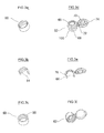
- FIGURES 3a, 3b and 3c respectively show a perspective top view, a sectioned top view and a perspective bottom view of a snap ring fitting 60.
- FIGURES 3d, 3e and 3f correspondingly, show a perspective top view, a sectioned top view and a perspective bottom view of a flip cap closure fitting 62.
- a fastening ring of the snap ring 60 is shown at 64, is convex, and conforms with a fastening ring 66 of the flip cap closure 62 which is concave.
- An opening of the flip cap closure 62 is shown at 68, and receives a cap closure sealing ring 70, which snaps into it.
- a living hinge 72 joins the top of the flip cap closure 62 (i.e, the right portion of FIGURE 3d ) with the base of the flip cap closure 62 (i.e., the left portion of FIGURE 3d ) while a pull tab 74 serves to open the flip cap closure 62 after the sealing ring 70 snaps into the opening 68.
- Reference numeral 76 in the sectioned top view of FIGURE 3e identifies a closure channel to position the tube of this aspect of the invention to accept the final assembly of the flip cap closure 62, the tube, and the snap ring 60 together. Such assembly is illustrated more specifically with reference to the various views of FIGURES 4a-4f .
- FIGURE 4a the piston 10 of FIGURES 1a-1d is shown at 82, a shoulder-less, nozzle-less, different type of cylindrical tube 80 is shown as having an open bottom end 84, an open top end 86, an optional airway hole 88 and an optional airway hole cover-up label 90 (similar to the airway hole 36, and cover-up label 38 of FIGURES 2a and 2b ).
- FIGURE 4a also shows the snap ring 60 of FIGURES 3a-3c and the flip cap closure 62 of FIGURES 3d-3f .
- FIGURE 4b illustrates the piston 82 inserted inside the tube 80, with the snap ring 60 being placed externally over the tube 80 and moved approximately one third of the way down from its open top end 86 towards its now sealed bottom end 84.
- the optional airway hole label 90 is applied to cover the optional airway hole 88.
- the flip top closure 62 is pushed into the open top end 86 of the tube 80 -- followed by the snap ring 60 being moved up from its one-third position to fasten together with the flip top closure 62 as in FIGURE 4d .
- the tube 80 is fabricated of a soft plastic (preferably Polyethylene) while the piston 80 is fabricated of a smooth, non-sticking, rigid plastic (preferably High Density Polyethylene).
- FIGURES 4e and 4f illustrate a sectional view of the assembly with the piston 82, the tube 80, the snap ring 60 and the flip top closure 62 in position after the piston 82 is pinched up from the sealed bottom end of the tube.
- the head of the piston 12 reaches all the way to the top of the flip cap closure 62, which together with the slightly larger diameter rings of the piston, allows for only a fractional amount of product/content to remain in the closed-off tube.
- FIGURE 4f illustrates a magnified sectional view of this, and shows at 94 the top of the tube's wall sandwiched between the snap ring's fastening ring 64 and the flip top closure's fastening ring 66 in forming a tight fit with the tube 80 in acting as a sealing gasket between the snap ring 60 and the flip cap closure 62. Additionally, at the area of the two fastening rings 64 and 66, the wall of the tube 80 conforms to the contour of the fastening rings 64 and 66 so as not to allow the possibility of leakage. This also serves to strengthen the bond between the parts, making them virtually undetachable.
- a leak resistant and non-removable assembly results, along with the further advantage of eliminating any use of adhesives, welding, heat sealing or other means to attach the components together as exist with the standard, conventional type of tubular reservoir container construction. A savings of manufacturing cost and time thus results as well.
- FIGURE 4f furthermore, illustrates the end of the tube 96 fitting into the channel 98 of the snap ring fitting 60 ( FIGURE 3c ), the snap ring 60 assembled with the tube 80 and the flip cap closure fitting 62, and the pushing and fitting together of the top end of the tube 86 with the channel of the cap closure 76 ( FIGURE 3e ).
- a new tube and closure system thus results, with the internal dispensing, extracting piston wedge glided forwardly by the thumb and index finger pinching action to drive substantially the entire viscous liquid product content out the tube.
- the viscous liquid product content could be added to the tube through an open bottom end before the piston is inserted and the open bottom end then sealed, or through an open top end after the piston is inserted and the bottom end sealed.
- the piston head 12 is of a length to extend through the closure cap opening 68 once its shoulder 20 contacts the bottom edge of the cap, at 100.
- piston drive of the invention is shown as being cylindrical in shape, the piston can be fabricated in other shapes as well -- such as oblong, oval, triangular, squarewhatever is needed to conform to the internal sectional arrangement of the tube employed, and to the tube opening.
- other types of internal closure fitting, snap ring combinations may be employed, again depending upon the cross-sectional configuration of the tube utilized with the internal drive system and upon the opening configuration.
Landscapes
- Engineering & Computer Science (AREA)
- Mechanical Engineering (AREA)
- Closures For Containers (AREA)
Priority Applications (1)
| Application Number | Priority Date | Filing Date | Title |
|---|---|---|---|
| EP12162955.4A EP2647583A1 (fr) | 2012-04-03 | 2012-04-03 | Tube de pincement extracteur de distribution avec piston interne |
Applications Claiming Priority (1)
| Application Number | Priority Date | Filing Date | Title |
|---|---|---|---|
| EP12162955.4A EP2647583A1 (fr) | 2012-04-03 | 2012-04-03 | Tube de pincement extracteur de distribution avec piston interne |
Publications (1)
| Publication Number | Publication Date |
|---|---|
| EP2647583A1 true EP2647583A1 (fr) | 2013-10-09 |
Family
ID=46000784
Family Applications (1)
| Application Number | Title | Priority Date | Filing Date |
|---|---|---|---|
| EP12162955.4A Withdrawn EP2647583A1 (fr) | 2012-04-03 | 2012-04-03 | Tube de pincement extracteur de distribution avec piston interne |
Country Status (1)
| Country | Link |
|---|---|
| EP (1) | EP2647583A1 (fr) |
Citations (6)
| Publication number | Priority date | Publication date | Assignee | Title |
|---|---|---|---|---|
| FR1384815A (fr) * | 1963-11-28 | 1965-01-08 | Perfectionnements aux conditionnements en tubes et ampoules souples | |
| GB1050837A (fr) * | 1965-08-06 | 1966-12-07 | ||
| FR2701927A1 (fr) * | 1993-02-23 | 1994-09-02 | Dubarry Gabriel | Dispositif d'extraction de matière gélifiée ou pâteuse conditionnée en tube. |
| WO2004039685A1 (fr) * | 2002-10-29 | 2004-05-13 | Enzo Ferrarin | Recipient pour matieres coulantes telles que des pates et des cremes |
| WO2007066123A1 (fr) * | 2005-12-10 | 2007-06-14 | William Arthur Bell | Dispositif comprenant un tube de distribution |
| WO2011087335A2 (fr) * | 2010-02-23 | 2011-07-21 | Woo Jong Won | Contenant tubulaire pourvu d'un piston servant à distribuer des substances visqueuses |
-
2012
- 2012-04-03 EP EP12162955.4A patent/EP2647583A1/fr not_active Withdrawn
Patent Citations (6)
| Publication number | Priority date | Publication date | Assignee | Title |
|---|---|---|---|---|
| FR1384815A (fr) * | 1963-11-28 | 1965-01-08 | Perfectionnements aux conditionnements en tubes et ampoules souples | |
| GB1050837A (fr) * | 1965-08-06 | 1966-12-07 | ||
| FR2701927A1 (fr) * | 1993-02-23 | 1994-09-02 | Dubarry Gabriel | Dispositif d'extraction de matière gélifiée ou pâteuse conditionnée en tube. |
| WO2004039685A1 (fr) * | 2002-10-29 | 2004-05-13 | Enzo Ferrarin | Recipient pour matieres coulantes telles que des pates et des cremes |
| WO2007066123A1 (fr) * | 2005-12-10 | 2007-06-14 | William Arthur Bell | Dispositif comprenant un tube de distribution |
| WO2011087335A2 (fr) * | 2010-02-23 | 2011-07-21 | Woo Jong Won | Contenant tubulaire pourvu d'un piston servant à distribuer des substances visqueuses |
Similar Documents
| Publication | Publication Date | Title |
|---|---|---|
| US2219604A (en) | Dispensing device | |
| US6062437A (en) | Container reducible in size during use, with dispenser spout fitted with check valve | |
| US8132695B2 (en) | Multiple dose delivery device with manually depressible actuator and one-way valve for storing and dispensing substances, and related method | |
| US11641923B2 (en) | Cosmetic container with a capped seal | |
| US20100072224A1 (en) | Fillable and/or refillable tube | |
| JP2021010737A (ja) | 便利なリフィル構造を有する化粧品容器 | |
| US4172536A (en) | Collapsible tube dispenser | |
| US20130284764A1 (en) | Dispenser with re-sealable floor | |
| US3580427A (en) | Cream dispenser with pleated walls and lip type opening | |
| EP3203872B1 (fr) | Dispositif de conditionnement et d'application au moyen d'une pipette | |
| US20130299513A1 (en) | Tube dispensing device | |
| US20120085786A1 (en) | Pinch tube with internal piston dispensing extractor | |
| JP6903905B2 (ja) | 液ダレ防止キャップおよびその製造方法 | |
| JP2019507620A (ja) | 液状製品、特にクリーム等の化粧用液状製品の圧縮可能なディスペンサ | |
| US20160058155A1 (en) | Container with dispensing tip | |
| JP6489851B2 (ja) | 二重容器 | |
| US9004796B2 (en) | Application device | |
| WO2014086720A1 (fr) | Dispositif de conditionnement et distribution au moyen d'une pipette | |
| US20120085787A1 (en) | Pinch tube with internal piston dispensing extractor and snap ring/closure cap fittings | |
| KR200488770Y1 (ko) | 역류방지용 튜브용기 고무막 캡 | |
| US11622607B2 (en) | Necklace for lotions and gels | |
| JP2014005060A (ja) | 逆流防止容器 | |
| EP2752250B1 (fr) | Tube pliable avec pompe distributrice et son procédé de fabrication | |
| KR101331846B1 (ko) | 내용물 배출용기 | |
| JP5573168B2 (ja) | 袋状容器 |
Legal Events
| Date | Code | Title | Description |
|---|---|---|---|
| PUAI | Public reference made under article 153(3) epc to a published international application that has entered the european phase |
Free format text: ORIGINAL CODE: 0009012 |
|
| AK | Designated contracting states |
Kind code of ref document: A1 Designated state(s): AL AT BE BG CH CY CZ DE DK EE ES FI FR GB GR HR HU IE IS IT LI LT LU LV MC MK MT NL NO PL PT RO RS SE SI SK SM TR |
|
| AX | Request for extension of the european patent |
Extension state: BA ME |
|
| STAA | Information on the status of an ep patent application or granted ep patent |
Free format text: STATUS: THE APPLICATION IS DEEMED TO BE WITHDRAWN |
|
| 18D | Application deemed to be withdrawn |
Effective date: 20140410 |