EP2647780A2 - Vorrichtung zum Befestigen von Platten mit einem gewissen Abstand von einer Struktur. - Google Patents
Vorrichtung zum Befestigen von Platten mit einem gewissen Abstand von einer Struktur. Download PDFInfo
- Publication number
- EP2647780A2 EP2647780A2 EP13305423.9A EP13305423A EP2647780A2 EP 2647780 A2 EP2647780 A2 EP 2647780A2 EP 13305423 A EP13305423 A EP 13305423A EP 2647780 A2 EP2647780 A2 EP 2647780A2
- Authority
- EP
- European Patent Office
- Prior art keywords
- jumper
- rider
- rod
- toothed
- slider
- Prior art date
- Legal status (The legal status is an assumption and is not a legal conclusion. Google has not performed a legal analysis and makes no representation as to the accuracy of the status listed.)
- Granted
Links
Images



Classifications
-
- E—FIXED CONSTRUCTIONS
- E04—BUILDING
- E04F—FINISHING WORK ON BUILDINGS, e.g. STAIRS, FLOORS
- E04F13/00—Coverings or linings, e.g. for walls or ceilings
- E04F13/07—Coverings or linings, e.g. for walls or ceilings composed of covering or lining elements; Sub-structures therefor; Fastening means therefor
- E04F13/08—Coverings or linings, e.g. for walls or ceilings composed of covering or lining elements; Sub-structures therefor; Fastening means therefor composed of a plurality of similar covering or lining elements
- E04F13/0801—Separate fastening elements
- E04F13/0803—Separate fastening elements with load-supporting elongated furring elements between wall and covering elements
- E04F13/0805—Separate fastening elements with load-supporting elongated furring elements between wall and covering elements with additional fastening elements between furring elements and the wall
- E04F13/0807—Separate fastening elements with load-supporting elongated furring elements between wall and covering elements with additional fastening elements between furring elements and the wall adjustable perpendicular to the wall
-
- F—MECHANICAL ENGINEERING; LIGHTING; HEATING; WEAPONS; BLASTING
- F16—ENGINEERING ELEMENTS AND UNITS; GENERAL MEASURES FOR PRODUCING AND MAINTAINING EFFECTIVE FUNCTIONING OF MACHINES OR INSTALLATIONS; THERMAL INSULATION IN GENERAL
- F16B—DEVICES FOR FASTENING OR SECURING CONSTRUCTIONAL ELEMENTS OR MACHINE PARTS TOGETHER, e.g. NAILS, BOLTS, CIRCLIPS, CLAMPS, CLIPS OR WEDGES; JOINTS OR JOINTING
- F16B21/00—Means for preventing relative axial movement of a pin, spigot, shaft or the like and a member surrounding it; Stud-and-socket releasable fastenings
- F16B21/06—Releasable fastening devices with snap-action
- F16B21/07—Releasable fastening devices with snap-action in which the socket has a resilient part
- F16B21/071—Releasable fastening devices with snap-action in which the socket has a resilient part the socket being integrally formed with a component to be fasted, e.g. a sheet, plate or strip
-
- F—MECHANICAL ENGINEERING; LIGHTING; HEATING; WEAPONS; BLASTING
- F16—ENGINEERING ELEMENTS AND UNITS; GENERAL MEASURES FOR PRODUCING AND MAINTAINING EFFECTIVE FUNCTIONING OF MACHINES OR INSTALLATIONS; THERMAL INSULATION IN GENERAL
- F16B—DEVICES FOR FASTENING OR SECURING CONSTRUCTIONAL ELEMENTS OR MACHINE PARTS TOGETHER, e.g. NAILS, BOLTS, CIRCLIPS, CLAMPS, CLIPS OR WEDGES; JOINTS OR JOINTING
- F16B21/00—Means for preventing relative axial movement of a pin, spigot, shaft or the like and a member surrounding it; Stud-and-socket releasable fastenings
- F16B21/06—Releasable fastening devices with snap-action
- F16B21/08—Releasable fastening devices with snap-action in which the stud, pin, or spigot has a resilient part
- F16B21/086—Releasable fastening devices with snap-action in which the stud, pin, or spigot has a resilient part the shank of the stud, pin or spigot having elevations, ribs, fins or prongs intended for deformation or tilting predominantly in a direction perpendicular to the direction of insertion
-
- F—MECHANICAL ENGINEERING; LIGHTING; HEATING; WEAPONS; BLASTING
- F16—ENGINEERING ELEMENTS AND UNITS; GENERAL MEASURES FOR PRODUCING AND MAINTAINING EFFECTIVE FUNCTIONING OF MACHINES OR INSTALLATIONS; THERMAL INSULATION IN GENERAL
- F16B—DEVICES FOR FASTENING OR SECURING CONSTRUCTIONAL ELEMENTS OR MACHINE PARTS TOGETHER, e.g. NAILS, BOLTS, CIRCLIPS, CLAMPS, CLIPS OR WEDGES; JOINTS OR JOINTING
- F16B21/00—Means for preventing relative axial movement of a pin, spigot, shaft or the like and a member surrounding it; Stud-and-socket releasable fastenings
- F16B21/09—Releasable fastening devices with a stud engaging a keyhole slot
-
- F—MECHANICAL ENGINEERING; LIGHTING; HEATING; WEAPONS; BLASTING
- F16—ENGINEERING ELEMENTS AND UNITS; GENERAL MEASURES FOR PRODUCING AND MAINTAINING EFFECTIVE FUNCTIONING OF MACHINES OR INSTALLATIONS; THERMAL INSULATION IN GENERAL
- F16B—DEVICES FOR FASTENING OR SECURING CONSTRUCTIONAL ELEMENTS OR MACHINE PARTS TOGETHER, e.g. NAILS, BOLTS, CIRCLIPS, CLAMPS, CLIPS OR WEDGES; JOINTS OR JOINTING
- F16B5/00—Joining sheets or plates, e.g. panels, to one another or to strips or bars parallel to them
- F16B5/06—Joining sheets or plates, e.g. panels, to one another or to strips or bars parallel to them by means of clamps or clips
- F16B5/0607—Joining sheets or plates, e.g. panels, to one another or to strips or bars parallel to them by means of clamps or clips joining sheets or plates to each other
- F16B5/0621—Joining sheets or plates, e.g. panels, to one another or to strips or bars parallel to them by means of clamps or clips joining sheets or plates to each other in parallel relationship
- F16B5/065—Joining sheets or plates, e.g. panels, to one another or to strips or bars parallel to them by means of clamps or clips joining sheets or plates to each other in parallel relationship the plates being one on top of the other and distanced from each other, e.g. by using protrusions to keep contact and distance
-
- F—MECHANICAL ENGINEERING; LIGHTING; HEATING; WEAPONS; BLASTING
- F16—ENGINEERING ELEMENTS AND UNITS; GENERAL MEASURES FOR PRODUCING AND MAINTAINING EFFECTIVE FUNCTIONING OF MACHINES OR INSTALLATIONS; THERMAL INSULATION IN GENERAL
- F16B—DEVICES FOR FASTENING OR SECURING CONSTRUCTIONAL ELEMENTS OR MACHINE PARTS TOGETHER, e.g. NAILS, BOLTS, CIRCLIPS, CLAMPS, CLIPS OR WEDGES; JOINTS OR JOINTING
- F16B7/00—Connections of rods or tubes, e.g. of non-circular section, mutually, including resilient connections
- F16B7/04—Clamping or clipping connections
- F16B7/044—Clamping or clipping connections for rods or tubes being in angled relationship
- F16B7/0446—Clamping or clipping connections for rods or tubes being in angled relationship for tubes using the innerside thereof
- F16B7/0473—Clamping or clipping connections for rods or tubes being in angled relationship for tubes using the innerside thereof with hook-like parts gripping, e.g. by expanding, behind the flanges of a profile
-
- E—FIXED CONSTRUCTIONS
- E04—BUILDING
- E04B—GENERAL BUILDING CONSTRUCTIONS; WALLS, e.g. PARTITIONS; ROOFS; FLOORS; CEILINGS; INSULATION OR OTHER PROTECTION OF BUILDINGS
- E04B9/00—Ceilings; Construction of ceilings, e.g. false ceilings; Ceiling construction with regard to insulation
- E04B9/18—Means for suspending the supporting construction
- E04B9/183—Means for suspending the supporting construction having a lower side adapted to be connected to a channel of the supporting construction
-
- E—FIXED CONSTRUCTIONS
- E04—BUILDING
- E04B—GENERAL BUILDING CONSTRUCTIONS; WALLS, e.g. PARTITIONS; ROOFS; FLOORS; CEILINGS; INSULATION OR OTHER PROTECTION OF BUILDINGS
- E04B9/00—Ceilings; Construction of ceilings, e.g. false ceilings; Ceiling construction with regard to insulation
- E04B9/18—Means for suspending the supporting construction
- E04B9/20—Means for suspending the supporting construction adjustable
Definitions
- the present invention relates to a device for fixing panels remote from a fixed support structure which may consist of a vertical wall (for example a wall or a partition) or a horizontal wall (for example a ceiling).
- connecting elements involving a threaded or notched rod whose first end is intended to be fixed to the fixed structure, while the second end cooperates with , in order to ensure an adjustable attachment, with a jumper shaped so as to snap into a profiled element or fur of substantially C-shaped section.
- This profile element is intended to serve as support for a doubling or facing.
- This jumper is frequently made from a strip of sheet metal cut and folded so as to obtain a substantially U-shaped structure whose lateral wings have curved ends and / or oblique each comprising a pair of opposite notches in which can engage the longitudinal edges of the profiled element.
- This profiled element comprises a flat core on which are fixed the ceiling panels or doubling. When laying, they allow to retain a layer of insulating material to provide insulation thermal and / or phonic between the panels and the support structure. The insulating material is seated on the threaded rod or notched by the second end of the rod.
- the object of the invention is therefore more particularly to eliminate these disadvantages. It proposes, for this purpose, a simpler fastening device to obtain a more reliable locking and durable over time even in the case where it has been the subject of several actuations.
- the jumper may comprise guide means inside which the toothed rod can slide
- the device may further comprise locking / unlocking means slidably mounted relative to said rider and having at least one notched surface arranged so that these locking / unlocking means can take at least two positions, an unlocked position in which the at least one toothed surface leaves the free passage of the toothed rod in the guide means and a locked position in which the notches of the at least one toothed surface of the locking / unlocking means are engaged with the notches of the toothed rod, so as to block the passage of the toothed rod in the guide means.
- This device conventionally comprises a notched pin designed to snap on a first profiled member or fur and a rider intended to clip on a second fur, the two furs being located in different substantially parallel planes. It is characterized by rectilinear guiding means of the notched rod inside the rider, in which the rod can slide, and by locking / unlocking means of the notched rod relative to this jumper, these locking means / unlocking being slidably mounted relative to the rider. This device does not involve rotational movement in its operation.
- the locking / unlocking means may comprise a slide movable in translation on the rider.
- These locking / unlocking means may take the form of a slider or drawer slidably mounted on a flat base of the rider.
- This slide has at least one notched surface whose notches are intended, in the locked position, to engage with the notches of the toothed rod, thereby preventing the sliding of the threaded rod in the guide means of the rider.
- the two series of notches are spaced apart and the threaded rod is free to slide linearly inside the jumper.
- the slide can be slidably mounted relative to the rider in a direction orthogonal to that of the sliding of the notched rod in the guide means.
- the toothed rod may comprise two longitudinal toothed surfaces arranged symmetrically with respect to a longitudinal axis of the toothed rod.
- the slider may comprise two toothed surfaces facing one another.
- the threaded rod and the slide each comprise two notched surfaces, the respective notches are intended to engage in the locking position.
- the guide means may comprise at least one stop provided to limit the sliding movement of said toothed rod in the guide means.
- a second end of the toothed rod can not abut against the inner face of the core of the fur on which the rider is clipped.
- the slider may comprise means for guiding and holding the rider.
- the guiding and holding means and said jumper may comprise stops which cooperate to limit in amplitude the sliding movement of the slide.
- the slider remains solitary rider, which, in use, has the advantage of limiting the number of parts of the device to two: the threaded rod and the jumper-slide assembly assembled.
- the jumper may further comprise a chimney which extends orthogonally with respect to the flat base and in the extension of the guide means, and inside which the toothed rod can slide.
- This chimney provides a better maintenance of the threaded rod, it allows in particular to maintain the rod even when it is completely out of the channel of the rider, and thus to obtain a greater latitude of adjustment for the device.
- the jumper may comprise on the flat base means for guiding and holding the slide.
- the guiding and holding means are on the base of the rider and not on the rider himself.
- the chimney may comprise at its end flanges parallel to said guide and holding means and forming slides for the slide.
- the device is more resistant to a tensile force exerted between the rider and the threaded rod, said flanges abutting on the upper edges of the sleeve.
- the first and second profiled elements 10a, 10b also called furs, are located in substantially parallel but offset planes.
- the second profiled element 10b is fixed to a fixed structure, for example a wall, a partition or a ceiling, and the first profiled element 10a is fixed orthogonally to the second profiled element 10b in order to receive a facing.
- the space between the wall, partition or ceiling and the siding is intended to be occupied by an insulating material.
- the first profiled element 10a is C-shaped comprising a core 11 ribbed in its central part and bordered by two parallel wings 12a, 12b, which extend perpendicular to the core 11 and are extended by two coplanar flanges 13a, 13b which extend towards each other by delimiting a longitudinal passage 14.
- the second profiled element 10b is generally identical.
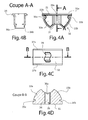
- the jumper 30 comprises a substantially rectangular flat base 32 having first and second faces 32a, 32b.
- the first face 32a is smooth.
- the second face 32b of this flat base extend two lateral wings 33a, 33b curved towards each other from small sides of the base 32.
- Each of these two wings comprises, in the vicinity of said base, a groove 35a, 35b which extends parallel to said short sides, these two grooves being intended to receive the two coplanar flanges 13a, 13b of a profiled element 10a of substantially C-shaped section.
- the rider 30 can be clipped on the profiled element 10a, the coplanar rims 13a, 13b taking place respectively in the grooves 35a, 35b.
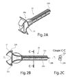
- the toothed rod 20 illustrated in Figures 2A and 2B comprises at a first end 20a a head 21 intended to be clipped on the second profiled element 10b fixed to the wall. For this purpose, it has grooves 22a, 22b for clipping in the same way as the rider 30 on this profile.
- the second end 20b is pointed, so as to facilitate the insertion of the insulating material on the rod once it clipped on the profiled element 10b.
- the rod 20 has two longitudinal toothed surfaces 23a, 23b, the notches being arranged radially.
- the cross section of the rod has an S shape, as illustrated in Figure 2C , the notches being located on the top and the base of the S.
- the cross section of the channel 34 of the jumper 30 reproduces the same shape of S, so that the toothed rod 20 can slide in this opening without pivoting, which contributes to ensuring the verticality of the profiled element 10a when approached and clipped on the jumper 30.
- the cross section of the rod 20 and the channel 34 could take any other form suitable for locking the rod in rotation in the channel, provided that the rod 20 comprises at least two longitudinal notched strips, for example of square or rectangular shape.
- the channel 34 comprises, near the base 32 of the jumper 30, a radial lug 39 whose profile is asymmetrical; this lug rubs against the notches of the notched rod 20 without preventing its sliding in the channel 34, but because of its asymmetrical profile, the friction in the direction of withdrawal of the rod 20 is greater than the friction in the direction of insertion .
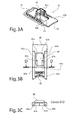
- a slider 40 is slidably attached to the rider 30.
- the slider 40 takes a position almost detached from the rider 30 that he can not take in use.
- the slider 40 comprises a substantially rectangular and flat plate, of longitudinal dimension greater than that of the base 32 of the rider and of transverse dimension slightly greater than that of this base.
- This plate has a first face 40a said inner face and a second face called outer face 40b.
- the inner face 40a of the slider 40 is defined as that which is intended to be turned towards the fixed support and the second profiled element 10b, the outer face 40b being defined as that which faces the first profiled element 10a.
- the inner face 40a is surmounted by a sleeve 41 open on one side and whose cross section thus has substantially the shape of a U.
- This plate further comprises a substantially rectangular opening 44 partially circumscribed by said sleeve 41.
- the extension transverse of this opening 44 is substantially equal to or slightly greater than the transverse extension of the toothed rod 20, so that the toothed rod can slide between the longitudinal edges 43a, 43b not toothed of this opening 44.
- the inner faces of the walls facing the sheath 41 comprise toothed surfaces 42a, 42b whose notches overhang the opening 44, reducing the space available for an object brought to slide in the opening 44, as illustrated in figure 3B .
- the toothed rod 20 can not slide between these notched surfaces 42a, 42b.
- the short sides of the slider 40 include means for facilitating its grip and manipulation by the user: a curved pedal 48 on a small side of the rectangular plate, and a curved conformation of the small opposite side 49.
- the locking is obtained by action of the user on the pedal 48.
- the sleeve 41 of the slider In a so-called unlocking or open position, the sleeve 41 of the slider is spaced from the toothed rod 20 when it is present in the channel 34, it can slide between the longitudinal edges 43a, 43b of the opening 44 of the slider 40 and also slides in the channel 34 of the rider. In a so-called locking or closed position, the sleeve 41 encloses the toothed rod 20, the notches of the toothed surfaces 42a, 42b are engaged with the notches of the toothed surfaces 23a, 23b of the toothed rod, the toothed rod is thus blocked in sliding.
- the notched rod 20 can thus penetrate and slide in the assembly constituted by the rider 30 and the slider 40, when this assembly is presented in front of the rod.
- Means are provided to limit this movement; it is appropriate that the rod does not come out of the channel 34 opposite the base 32 to not interfere with the introduction of the first profiled element 10a on the jumper 30.
- radial stops 36a, 36b are arranged in the vicinity of the opening of the channel 34 located opposite the flat base 32. The second end 20b of the toothed rod abuts against these radial stops 36a, 36b.
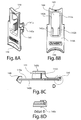
- the jumper 130 comprises a substantially octagonal irregular flat base 132 having first and second faces 132a, 132b.
- the first face 132a has two lateral flanges forming slides 136a, 136b which will be described later.
- From the second face 132b of this flat base extend two lateral wings 133a, 133b curved towards each other from opposite sides of the base 132.
- Each of these two wings comprises, in the vicinity of said base, a groove 135a, 135b which extends parallel to said sides, these two grooves being intended to receive the two coplanar flanges 13a, 13b of a profiled element 10a of substantially C-shaped section.
- the jumper 130 can be clipped on the profiled element 10a.
- the cross section of the rod 20 and the channel 134 can take any shape suitable for locking the rod in rotation in the channel, provided that the rod 20 comprises at least two longitudinal serrated strips, for example square or rectangular.
- the jumper 130 of the second embodiment differs in particular from the first embodiment described above in that the first face 132a of the base 132 is not smooth but surmounted by a chimney 138 which comes in the extension.
- This chimney is intended to ensure better maintenance of the toothed rod 20 when it slides in the jumper 130, that is to say in the channel 134 and in the chimney 138.
- the chimney 138 consists of two walls 138a, 138b parallel and opposite, joined at the top by a ring 138c substantially rectangular.
- the chimney 138 thus comprises two longitudinal openings 138d, 138e between the walls 138a, 138b, these openings being intended to allow the passage to the notches of the toothed surfaces 23a, 23b of the toothed rod 20 when sliding inside this chimney .
- a wall 138b of the chimney 138 has, near the base 132 of the jumper 130, a radial lug 139c whose profile is asymmetrical and whose function is identical.
- a slider 140 is slidably attached to the rider 130.
- the slider 140 has a substantially rectangular and flat plate, of longitudinal dimension greater than that of the base 132 of the rider and transverse dimension smaller than that of this base.
- This plate has a first face 140a called inner face and a second face called outer face 140b whose definitions are identical to those of the first embodiment.
- the inner face 140a is surmounted on a sleeve 141 open on one side and whose cross section thus has the shape of a U.
- This plate further comprises a substantially rectangular opening 144 partially circumscribed by said sleeve 141.
- the extension transverse of this opening 144 is greater than the transverse extension of the chimney 138 of the jumper 130, so that the chimney can slide in this opening 144 and between the longitudinal edges of the sheath 141.
- the slider 140 no longer comprises a slider rim on its outer face 140b, which is smooth, with the exception of a stop 140c which will be described later.
- the two facing faces of the sheath 141 comprise notched surfaces 142a, 142b whose notches are overhanging the opening 144, reducing the space available for an object slid into the opening 144, as illustrated in Figure 8B .
- the toothed rod 20 can not slide between these notched surfaces 142a, 142b.
- the short sides of the slider 140 include means to facilitate its grip and manipulation by the user: a curved pedal 148 on a small side of the rectangular plate, and a curved conformation of the opposite small side 149.
- the lock is obtained by action of the user on the pedal 148.
- the slide 140 slides and is held on the first face 132a of the flat base 132 of the rider with lateral projecting flanges 136a, 136b disposed on the base 132 of the rider 130, these defining edges of the grooves 157a, 157b.
- this degree of freedom in sliding is limited by a stop 140c projecting from the outer face 140b of the slide 140, in the vicinity of the short curved side 149. In the opening movement of the slide, this stop 140c comes into contact of the base 132 of the rider and prevents the slide from escaping the grooves 157a, 157b of the rider.
- the gadroons are small enough not to block the sliding of the slide, but crossing the rectilinear edge of the ears marks the user the transition from an open position to a closed position and vice versa.
- the sheath 141 of the slide is spaced from the chimney 138 and the toothed rod 20 when it is present in the chimney; the toothed rod 20 can slide in the chimney 138 and between the notched edges 143a, 143b of the opening 144 of the slider 140 and also slides in the channel 134 of the rider.
- the toothed rod 20 can thus penetrate and slide in the assembly formed by the rider 130 and the slide 140, when this assembly is presented in front of the rod.
- Means are provided to limit this movement; it is appropriate that the rod does not come out of the channel 134 opposite the base 132 to not interfere with the introduction of the first profiled element 10a on the jumper 130.
- radial stops 139a, 139b are arranged in the vicinity of the opening of the channel 134 located opposite the flat base 132. The second end 20b of the toothed rod abuts against these radial stops.
- the sheath 141 encloses the chimney 138 and the toothed rod 20. Due to the longitudinal openings 138d, 138e in the chimney 138, the notches of the toothed rod 20 are projecting with respect to this chimney and the notches of the notched surfaces 142a, 142b the sheath 141 are engaged with the notches of the toothed surfaces 23a, 23b of the toothed rod, the toothed rod is thus locked in sliding.
- the entire device may be made of a molded plastic material, preferably reinforced with glass fibers.
Landscapes
- Engineering & Computer Science (AREA)
- General Engineering & Computer Science (AREA)
- Mechanical Engineering (AREA)
- Architecture (AREA)
- Civil Engineering (AREA)
- Structural Engineering (AREA)
- Mutual Connection Of Rods And Tubes (AREA)
- Connection Of Plates (AREA)
Applications Claiming Priority (1)
| Application Number | Priority Date | Filing Date | Title |
|---|---|---|---|
| FR1253175A FR2989134B1 (fr) | 2012-04-05 | 2012-04-05 | Dispositif de fixation de panneaux a distance d'une structure. |
Publications (3)
| Publication Number | Publication Date |
|---|---|
| EP2647780A2 true EP2647780A2 (de) | 2013-10-09 |
| EP2647780A3 EP2647780A3 (de) | 2017-11-15 |
| EP2647780B1 EP2647780B1 (de) | 2020-04-15 |
Family
ID=47019077
Family Applications (1)
| Application Number | Title | Priority Date | Filing Date |
|---|---|---|---|
| EP13305423.9A Active EP2647780B1 (de) | 2012-04-05 | 2013-04-02 | Vorrichtung zum Befestigen von Platten mit einem gewissen Abstand von einer Struktur. |
Country Status (2)
| Country | Link |
|---|---|
| EP (1) | EP2647780B1 (de) |
| FR (1) | FR2989134B1 (de) |
Cited By (5)
| Publication number | Priority date | Publication date | Assignee | Title |
|---|---|---|---|---|
| WO2015155425A1 (fr) | 2014-04-09 | 2015-10-15 | Thierry Azerad | Dispositif d'adaptation destiné à recevoir l'extrémité d'une tige formant élément de maintien pour un élément de construction enserré par l'élément de maintien |
| WO2017042521A1 (fr) * | 2015-09-11 | 2017-03-16 | Stiplastics | Dispositif de maintien d'un élément de parement a distance d'une membrane pare-vapeur et système constructif a double armature comprenant un tel dispositif |
| FR3110189A1 (fr) * | 2020-05-14 | 2021-11-19 | Thierry Azerad | Dispositif d’entretoisement, doublage d’une paroi incluant un film traversé par la tige de tels dispositifs, et procédé de montage d’un élément stoppeur destiné à supporter un film dans un doublage de paroi |
| FR3120101A1 (fr) * | 2021-02-24 | 2022-08-26 | Zifort | Dispositif de fixation de panneaux à distance d’une structure |
| US20220290441A1 (en) * | 2019-10-25 | 2022-09-15 | Muotolevy Oy | Facade cladding fastening system and method for fastening facade and adjusting member |
Families Citing this family (1)
| Publication number | Priority date | Publication date | Assignee | Title |
|---|---|---|---|---|
| FR3140389B1 (fr) | 2022-10-03 | 2024-11-15 | Zifort | Système d’étanchéité pour membrane réaliser une étanchéité au moins à l’air le long d’un mur |
Citations (1)
| Publication number | Priority date | Publication date | Assignee | Title |
|---|---|---|---|---|
| FR2809125A1 (fr) | 2000-05-19 | 2001-11-23 | Placoplatre Lambert | Dispositif de liaison a pince et tige filetee, pour fourrures appartenant a des ossatures differentes, et pince pour un tel dispositif |
Family Cites Families (5)
| Publication number | Priority date | Publication date | Assignee | Title |
|---|---|---|---|---|
| NL9400159A (nl) * | 1994-02-02 | 1995-09-01 | Wit J H En Zonen De | Universele pijpbeugel. |
| FR2874040B1 (fr) * | 2004-08-06 | 2008-06-27 | L R Etanco Soc Par Actions Sim | Dispositif pour la fixation de panneaux sur une structure support fixe |
| FR2878876B1 (fr) * | 2004-12-06 | 2007-02-09 | Saint Gobain Isover Sa | Doublage de paroi a installation ergonomique |
| FR2914967B1 (fr) * | 2007-04-13 | 2010-11-05 | Raymond A & Cie | Pince a fixation sur tige filetee support de revetement de plafond. |
| FR2930006B1 (fr) * | 2008-12-16 | 2010-03-19 | Thierry Azerad | Dispositif de fixation et de reglage rapide d'ossatures metalliques recevant un isolant |
-
2012
- 2012-04-05 FR FR1253175A patent/FR2989134B1/fr not_active Expired - Fee Related
-
2013
- 2013-04-02 EP EP13305423.9A patent/EP2647780B1/de active Active
Patent Citations (1)
| Publication number | Priority date | Publication date | Assignee | Title |
|---|---|---|---|---|
| FR2809125A1 (fr) | 2000-05-19 | 2001-11-23 | Placoplatre Lambert | Dispositif de liaison a pince et tige filetee, pour fourrures appartenant a des ossatures differentes, et pince pour un tel dispositif |
Cited By (9)
| Publication number | Priority date | Publication date | Assignee | Title |
|---|---|---|---|---|
| WO2015155425A1 (fr) | 2014-04-09 | 2015-10-15 | Thierry Azerad | Dispositif d'adaptation destiné à recevoir l'extrémité d'une tige formant élément de maintien pour un élément de construction enserré par l'élément de maintien |
| FR3019863A1 (fr) * | 2014-04-09 | 2015-10-16 | Thierry Azerad | Dispositif d'adaptation destine a recevoir l'extremite d'une tige formant element de maintien pour un element de construction enserre par l'element de maintien |
| WO2017042521A1 (fr) * | 2015-09-11 | 2017-03-16 | Stiplastics | Dispositif de maintien d'un élément de parement a distance d'une membrane pare-vapeur et système constructif a double armature comprenant un tel dispositif |
| FR3041007A1 (fr) * | 2015-09-11 | 2017-03-17 | Stiplastics | Dispositif de maintien d'un element de parement a distance d'une membrane pare-vapeur et systeme constructif a double armature comprenant un tel dispositif |
| US20220290441A1 (en) * | 2019-10-25 | 2022-09-15 | Muotolevy Oy | Facade cladding fastening system and method for fastening facade and adjusting member |
| US11719000B2 (en) * | 2019-10-25 | 2023-08-08 | Muotolevy Oy | Facade cladding fastening system and method for fastening facade and adjusting member |
| FR3110189A1 (fr) * | 2020-05-14 | 2021-11-19 | Thierry Azerad | Dispositif d’entretoisement, doublage d’une paroi incluant un film traversé par la tige de tels dispositifs, et procédé de montage d’un élément stoppeur destiné à supporter un film dans un doublage de paroi |
| FR3120101A1 (fr) * | 2021-02-24 | 2022-08-26 | Zifort | Dispositif de fixation de panneaux à distance d’une structure |
| EP4053421A1 (de) * | 2021-02-24 | 2022-09-07 | Zifort | Vorrichtung zum befestigen von platten in einem abstand von einer struktur |
Also Published As
| Publication number | Publication date |
|---|---|
| FR2989134B1 (fr) | 2014-12-26 |
| FR2989134A1 (fr) | 2013-10-11 |
| EP2647780B1 (de) | 2020-04-15 |
| EP2647780A3 (de) | 2017-11-15 |
Similar Documents
| Publication | Publication Date | Title |
|---|---|---|
| EP2647780B1 (de) | Vorrichtung zum Befestigen von Platten mit einem gewissen Abstand von einer Struktur. | |
| EP2251522A1 (de) | Durchsichtiger Sicherheitsvorhang | |
| EP0359638B1 (de) | Zusammenstellungssystem für Profile | |
| EP0273841B1 (de) | Schliessblech für Schiebetür, -fenster oder dergleichen | |
| FR2912438A1 (fr) | Systeme de fixation de fausses parois non parfaitement tendues | |
| EP2415954A1 (de) | Einsatzbeschlag, der einen Befestigungsflansch umfasst | |
| EP3938611B1 (de) | Metallblende, insbesondere zum schutz gegen zyklone | |
| EP0855776B1 (de) | Befestigungsvorrichtung für einen elektrischen Rohrleiter | |
| EP2360381B1 (de) | Anschlusselement für Schwellenleiste | |
| FR2895939A1 (fr) | Crochet de reception d'un tourillon d'articulation | |
| FR2509777A1 (fr) | Dispositif de renvoi de coin pour ferrures a tiges actives ou tiges de commande de fenetres et de portes ou d'autres elements du meme genre | |
| FR3136494A3 (fr) | Système de lambris et raccord | |
| FR2874040A1 (fr) | Dispositif pour la fixation de panneaux sur une structure support fixe | |
| EP0803624A1 (de) | Teibstangenverschluss und Treibstange | |
| FR2486579A1 (fr) | Charniere pour fenetres basculantes dotees de profiles externes de recouvrement | |
| FR2857040A1 (fr) | Dispositif pour l'assemblage d'elements profiles de menuiserie | |
| EP4455429B1 (de) | Sicht- oder verdunkelungspaneel für starre gitterzäune und befestigungsverfahren dafür | |
| FR3020649A1 (fr) | Abri de piscine a modules telescopiques comprenant un mecanisme de deplacement ameliore des modules | |
| FR3166160A1 (fr) | Ouvrant vitré de menuiserie, menuiserie comprenant un tel ouvrant et procede de fabrication d’un tel ouvrant | |
| FR2738862A1 (fr) | Barriere modulable | |
| FR2908178A1 (fr) | Assemblage de deux profiles creux perpendiculaires | |
| FR2861776A1 (fr) | Barreau-support pour garde-corps | |
| FR3013375A1 (fr) | Dispositif de fixation d'un element de serrure | |
| EP0427644A1 (de) | Befestigungsvorrichtung für Scheiben, Tafeln oder dergleichen an einer Auflage, und mit der Vorrichtung ausgerüstete Türen, Fenster oder dergleichen | |
| FR2520425A1 (fr) | Dispositif de renvoi de coin pour ferrures a tiges actives ou tiges de commande de fenetres, de portes ou d'autres elements du meme genre |
Legal Events
| Date | Code | Title | Description |
|---|---|---|---|
| PUAI | Public reference made under article 153(3) epc to a published international application that has entered the european phase |
Free format text: ORIGINAL CODE: 0009012 |
|
| 17P | Request for examination filed |
Effective date: 20130402 |
|
| AK | Designated contracting states |
Kind code of ref document: A2 Designated state(s): AL AT BE BG CH CY CZ DE DK EE ES FI FR GB GR HR HU IE IS IT LI LT LU LV MC MK MT NL NO PL PT RO RS SE SI SK SM TR |
|
| AX | Request for extension of the european patent |
Extension state: BA ME |
|
| PUAL | Search report despatched |
Free format text: ORIGINAL CODE: 0009013 |
|
| STAA | Information on the status of an ep patent application or granted ep patent |
Free format text: STATUS: EXAMINATION IS IN PROGRESS |
|
| AK | Designated contracting states |
Kind code of ref document: A3 Designated state(s): AL AT BE BG CH CY CZ DE DK EE ES FI FR GB GR HR HU IE IS IT LI LT LU LV MC MK MT NL NO PL PT RO RS SE SI SK SM TR |
|
| AX | Request for extension of the european patent |
Extension state: BA ME |
|
| RIC1 | Information provided on ipc code assigned before grant |
Ipc: E04B 9/20 20060101ALI20171009BHEP Ipc: E04F 13/08 20060101AFI20171009BHEP Ipc: F16B 2/20 20060101ALI20171009BHEP Ipc: F16B 37/08 20060101ALI20171009BHEP |
|
| 17Q | First examination report despatched |
Effective date: 20171102 |
|
| GRAP | Despatch of communication of intention to grant a patent |
Free format text: ORIGINAL CODE: EPIDOSNIGR1 |
|
| STAA | Information on the status of an ep patent application or granted ep patent |
Free format text: STATUS: GRANT OF PATENT IS INTENDED |
|
| INTG | Intention to grant announced |
Effective date: 20191104 |
|
| GRAS | Grant fee paid |
Free format text: ORIGINAL CODE: EPIDOSNIGR3 |
|
| GRAA | (expected) grant |
Free format text: ORIGINAL CODE: 0009210 |
|
| STAA | Information on the status of an ep patent application or granted ep patent |
Free format text: STATUS: THE PATENT HAS BEEN GRANTED |
|
| AK | Designated contracting states |
Kind code of ref document: B1 Designated state(s): AL AT BE BG CH CY CZ DE DK EE ES FI FR GB GR HR HU IE IS IT LI LT LU LV MC MK MT NL NO PL PT RO RS SE SI SK SM TR |
|
| REG | Reference to a national code |
Ref country code: CH Ref legal event code: EP Ref country code: GB Ref legal event code: FG4D Free format text: NOT ENGLISH |
|
| REG | Reference to a national code |
Ref country code: DE Ref legal event code: R096 Ref document number: 602013067894 Country of ref document: DE |
|
| REG | Reference to a national code |
Ref country code: IE Ref legal event code: FG4D Free format text: LANGUAGE OF EP DOCUMENT: FRENCH |
|
| REG | Reference to a national code |
Ref country code: AT Ref legal event code: REF Ref document number: 1257454 Country of ref document: AT Kind code of ref document: T Effective date: 20200515 |
|
| REG | Reference to a national code |
Ref country code: NL Ref legal event code: MP Effective date: 20200415 |
|
| REG | Reference to a national code |
Ref country code: LT Ref legal event code: MG4D |
|
| PG25 | Lapsed in a contracting state [announced via postgrant information from national office to epo] |
Ref country code: PT Free format text: LAPSE BECAUSE OF FAILURE TO SUBMIT A TRANSLATION OF THE DESCRIPTION OR TO PAY THE FEE WITHIN THE PRESCRIBED TIME-LIMIT Effective date: 20200817 Ref country code: LT Free format text: LAPSE BECAUSE OF FAILURE TO SUBMIT A TRANSLATION OF THE DESCRIPTION OR TO PAY THE FEE WITHIN THE PRESCRIBED TIME-LIMIT Effective date: 20200415 Ref country code: NO Free format text: LAPSE BECAUSE OF FAILURE TO SUBMIT A TRANSLATION OF THE DESCRIPTION OR TO PAY THE FEE WITHIN THE PRESCRIBED TIME-LIMIT Effective date: 20200715 Ref country code: FI Free format text: LAPSE BECAUSE OF FAILURE TO SUBMIT A TRANSLATION OF THE DESCRIPTION OR TO PAY THE FEE WITHIN THE PRESCRIBED TIME-LIMIT Effective date: 20200415 Ref country code: NL Free format text: LAPSE BECAUSE OF FAILURE TO SUBMIT A TRANSLATION OF THE DESCRIPTION OR TO PAY THE FEE WITHIN THE PRESCRIBED TIME-LIMIT Effective date: 20200415 Ref country code: IS Free format text: LAPSE BECAUSE OF FAILURE TO SUBMIT A TRANSLATION OF THE DESCRIPTION OR TO PAY THE FEE WITHIN THE PRESCRIBED TIME-LIMIT Effective date: 20200815 Ref country code: SE Free format text: LAPSE BECAUSE OF FAILURE TO SUBMIT A TRANSLATION OF THE DESCRIPTION OR TO PAY THE FEE WITHIN THE PRESCRIBED TIME-LIMIT Effective date: 20200415 Ref country code: GR Free format text: LAPSE BECAUSE OF FAILURE TO SUBMIT A TRANSLATION OF THE DESCRIPTION OR TO PAY THE FEE WITHIN THE PRESCRIBED TIME-LIMIT Effective date: 20200716 |
|
| REG | Reference to a national code |
Ref country code: AT Ref legal event code: MK05 Ref document number: 1257454 Country of ref document: AT Kind code of ref document: T Effective date: 20200415 |
|
| PG25 | Lapsed in a contracting state [announced via postgrant information from national office to epo] |
Ref country code: HR Free format text: LAPSE BECAUSE OF FAILURE TO SUBMIT A TRANSLATION OF THE DESCRIPTION OR TO PAY THE FEE WITHIN THE PRESCRIBED TIME-LIMIT Effective date: 20200415 Ref country code: RS Free format text: LAPSE BECAUSE OF FAILURE TO SUBMIT A TRANSLATION OF THE DESCRIPTION OR TO PAY THE FEE WITHIN THE PRESCRIBED TIME-LIMIT Effective date: 20200415 Ref country code: LV Free format text: LAPSE BECAUSE OF FAILURE TO SUBMIT A TRANSLATION OF THE DESCRIPTION OR TO PAY THE FEE WITHIN THE PRESCRIBED TIME-LIMIT Effective date: 20200415 Ref country code: BG Free format text: LAPSE BECAUSE OF FAILURE TO SUBMIT A TRANSLATION OF THE DESCRIPTION OR TO PAY THE FEE WITHIN THE PRESCRIBED TIME-LIMIT Effective date: 20200715 |
|
| PG25 | Lapsed in a contracting state [announced via postgrant information from national office to epo] |
Ref country code: AL Free format text: LAPSE BECAUSE OF FAILURE TO SUBMIT A TRANSLATION OF THE DESCRIPTION OR TO PAY THE FEE WITHIN THE PRESCRIBED TIME-LIMIT Effective date: 20200415 |
|
| REG | Reference to a national code |
Ref country code: DE Ref legal event code: R097 Ref document number: 602013067894 Country of ref document: DE |
|
| PG25 | Lapsed in a contracting state [announced via postgrant information from national office to epo] |
Ref country code: ES Free format text: LAPSE BECAUSE OF FAILURE TO SUBMIT A TRANSLATION OF THE DESCRIPTION OR TO PAY THE FEE WITHIN THE PRESCRIBED TIME-LIMIT Effective date: 20200415 Ref country code: CZ Free format text: LAPSE BECAUSE OF FAILURE TO SUBMIT A TRANSLATION OF THE DESCRIPTION OR TO PAY THE FEE WITHIN THE PRESCRIBED TIME-LIMIT Effective date: 20200415 Ref country code: RO Free format text: LAPSE BECAUSE OF FAILURE TO SUBMIT A TRANSLATION OF THE DESCRIPTION OR TO PAY THE FEE WITHIN THE PRESCRIBED TIME-LIMIT Effective date: 20200415 Ref country code: IT Free format text: LAPSE BECAUSE OF FAILURE TO SUBMIT A TRANSLATION OF THE DESCRIPTION OR TO PAY THE FEE WITHIN THE PRESCRIBED TIME-LIMIT Effective date: 20200415 Ref country code: AT Free format text: LAPSE BECAUSE OF FAILURE TO SUBMIT A TRANSLATION OF THE DESCRIPTION OR TO PAY THE FEE WITHIN THE PRESCRIBED TIME-LIMIT Effective date: 20200415 Ref country code: EE Free format text: LAPSE BECAUSE OF FAILURE TO SUBMIT A TRANSLATION OF THE DESCRIPTION OR TO PAY THE FEE WITHIN THE PRESCRIBED TIME-LIMIT Effective date: 20200415 Ref country code: SM Free format text: LAPSE BECAUSE OF FAILURE TO SUBMIT A TRANSLATION OF THE DESCRIPTION OR TO PAY THE FEE WITHIN THE PRESCRIBED TIME-LIMIT Effective date: 20200415 Ref country code: DK Free format text: LAPSE BECAUSE OF FAILURE TO SUBMIT A TRANSLATION OF THE DESCRIPTION OR TO PAY THE FEE WITHIN THE PRESCRIBED TIME-LIMIT Effective date: 20200415 |
|
| PLBE | No opposition filed within time limit |
Free format text: ORIGINAL CODE: 0009261 |
|
| STAA | Information on the status of an ep patent application or granted ep patent |
Free format text: STATUS: NO OPPOSITION FILED WITHIN TIME LIMIT |
|
| PG25 | Lapsed in a contracting state [announced via postgrant information from national office to epo] |
Ref country code: SK Free format text: LAPSE BECAUSE OF FAILURE TO SUBMIT A TRANSLATION OF THE DESCRIPTION OR TO PAY THE FEE WITHIN THE PRESCRIBED TIME-LIMIT Effective date: 20200415 Ref country code: PL Free format text: LAPSE BECAUSE OF FAILURE TO SUBMIT A TRANSLATION OF THE DESCRIPTION OR TO PAY THE FEE WITHIN THE PRESCRIBED TIME-LIMIT Effective date: 20200415 |
|
| 26N | No opposition filed |
Effective date: 20210118 |
|
| PG25 | Lapsed in a contracting state [announced via postgrant information from national office to epo] |
Ref country code: SI Free format text: LAPSE BECAUSE OF FAILURE TO SUBMIT A TRANSLATION OF THE DESCRIPTION OR TO PAY THE FEE WITHIN THE PRESCRIBED TIME-LIMIT Effective date: 20200415 |
|
| PG25 | Lapsed in a contracting state [announced via postgrant information from national office to epo] |
Ref country code: MC Free format text: LAPSE BECAUSE OF FAILURE TO SUBMIT A TRANSLATION OF THE DESCRIPTION OR TO PAY THE FEE WITHIN THE PRESCRIBED TIME-LIMIT Effective date: 20200415 |
|
| GBPC | Gb: european patent ceased through non-payment of renewal fee |
Effective date: 20210402 |
|
| PG25 | Lapsed in a contracting state [announced via postgrant information from national office to epo] |
Ref country code: LU Free format text: LAPSE BECAUSE OF NON-PAYMENT OF DUE FEES Effective date: 20210402 |
|
| PG25 | Lapsed in a contracting state [announced via postgrant information from national office to epo] |
Ref country code: CH Free format text: LAPSE BECAUSE OF NON-PAYMENT OF DUE FEES Effective date: 20210430 Ref country code: LI Free format text: LAPSE BECAUSE OF NON-PAYMENT OF DUE FEES Effective date: 20210430 Ref country code: GB Free format text: LAPSE BECAUSE OF NON-PAYMENT OF DUE FEES Effective date: 20210402 |
|
| PG25 | Lapsed in a contracting state [announced via postgrant information from national office to epo] |
Ref country code: IE Free format text: LAPSE BECAUSE OF NON-PAYMENT OF DUE FEES Effective date: 20210402 |
|
| PG25 | Lapsed in a contracting state [announced via postgrant information from national office to epo] |
Ref country code: HU Free format text: LAPSE BECAUSE OF FAILURE TO SUBMIT A TRANSLATION OF THE DESCRIPTION OR TO PAY THE FEE WITHIN THE PRESCRIBED TIME-LIMIT; INVALID AB INITIO Effective date: 20130402 |
|
| PG25 | Lapsed in a contracting state [announced via postgrant information from national office to epo] |
Ref country code: CY Free format text: LAPSE BECAUSE OF FAILURE TO SUBMIT A TRANSLATION OF THE DESCRIPTION OR TO PAY THE FEE WITHIN THE PRESCRIBED TIME-LIMIT Effective date: 20200415 |
|
| P01 | Opt-out of the competence of the unified patent court (upc) registered |
Effective date: 20230526 |
|
| REG | Reference to a national code |
Ref country code: DE Ref legal event code: R082 Ref document number: 602013067894 Country of ref document: DE Representative=s name: KASTEL PATENTANWAELTE PARTG MBB, DE |
|
| PG25 | Lapsed in a contracting state [announced via postgrant information from national office to epo] |
Ref country code: MK Free format text: LAPSE BECAUSE OF FAILURE TO SUBMIT A TRANSLATION OF THE DESCRIPTION OR TO PAY THE FEE WITHIN THE PRESCRIBED TIME-LIMIT Effective date: 20200415 |
|
| PG25 | Lapsed in a contracting state [announced via postgrant information from national office to epo] |
Ref country code: MT Free format text: LAPSE BECAUSE OF FAILURE TO SUBMIT A TRANSLATION OF THE DESCRIPTION OR TO PAY THE FEE WITHIN THE PRESCRIBED TIME-LIMIT Effective date: 20200415 |
|
| PGFP | Annual fee paid to national office [announced via postgrant information from national office to epo] |
Ref country code: DE Payment date: 20250528 Year of fee payment: 13 |
|
| PGFP | Annual fee paid to national office [announced via postgrant information from national office to epo] |
Ref country code: BE Payment date: 20250425 Year of fee payment: 13 |
|
| PGFP | Annual fee paid to national office [announced via postgrant information from national office to epo] |
Ref country code: FR Payment date: 20250429 Year of fee payment: 13 |
|
| PG25 | Lapsed in a contracting state [announced via postgrant information from national office to epo] |
Ref country code: TR Free format text: LAPSE BECAUSE OF FAILURE TO SUBMIT A TRANSLATION OF THE DESCRIPTION OR TO PAY THE FEE WITHIN THE PRESCRIBED TIME-LIMIT Effective date: 20200415 |