EP2647785B1 - Einteiliger Scharnierkörper und Scharnieranordnung für schwenkbare Elemente - Google Patents
Einteiliger Scharnierkörper und Scharnieranordnung für schwenkbare Elemente Download PDFInfo
- Publication number
- EP2647785B1 EP2647785B1 EP12162920.8A EP12162920A EP2647785B1 EP 2647785 B1 EP2647785 B1 EP 2647785B1 EP 12162920 A EP12162920 A EP 12162920A EP 2647785 B1 EP2647785 B1 EP 2647785B1
- Authority
- EP
- European Patent Office
- Prior art keywords
- hinge
- profile
- profiles
- hinge body
- terminal ends
- Prior art date
- Legal status (The legal status is an assumption and is not a legal conclusion. Google has not performed a legal analysis and makes no representation as to the accuracy of the status listed.)
- Active
Links
Images




Classifications
-
- E—FIXED CONSTRUCTIONS
- E05—LOCKS; KEYS; WINDOW OR DOOR FITTINGS; SAFES
- E05D—HINGES OR SUSPENSION DEVICES FOR DOORS, WINDOWS OR WINGS
- E05D1/00—Pinless hinges; Substitutes for hinges
- E05D1/02—Pinless hinges; Substitutes for hinges made of one piece
-
- E—FIXED CONSTRUCTIONS
- E05—LOCKS; KEYS; WINDOW OR DOOR FITTINGS; SAFES
- E05D—HINGES OR SUSPENSION DEVICES FOR DOORS, WINDOWS OR WINGS
- E05D1/00—Pinless hinges; Substitutes for hinges
- E05D1/04—Pinless hinges; Substitutes for hinges with guide members shaped as circular arcs
-
- E—FIXED CONSTRUCTIONS
- E05—LOCKS; KEYS; WINDOW OR DOOR FITTINGS; SAFES
- E05D—HINGES OR SUSPENSION DEVICES FOR DOORS, WINDOWS OR WINGS
- E05D5/00—Construction of single parts, e.g. the parts for attachment
- E05D5/10—Pins, sockets or sleeves; Removable pins
- E05D5/14—Construction of sockets or sleeves
-
- E—FIXED CONSTRUCTIONS
- E05—LOCKS; KEYS; WINDOW OR DOOR FITTINGS; SAFES
- E05D—HINGES OR SUSPENSION DEVICES FOR DOORS, WINDOWS OR WINGS
- E05D7/00—Hinges or pivots of special construction
-
- E—FIXED CONSTRUCTIONS
- E05—LOCKS; KEYS; WINDOW OR DOOR FITTINGS; SAFES
- E05D—HINGES OR SUSPENSION DEVICES FOR DOORS, WINDOWS OR WINGS
- E05D5/00—Construction of single parts, e.g. the parts for attachment
- E05D5/10—Pins, sockets or sleeves; Removable pins
- E05D5/14—Construction of sockets or sleeves
- E05D2005/145—Construction of sockets or sleeves with elastically deformable parts
-
- E—FIXED CONSTRUCTIONS
- E05—LOCKS; KEYS; WINDOW OR DOOR FITTINGS; SAFES
- E05D—HINGES OR SUSPENSION DEVICES FOR DOORS, WINDOWS OR WINGS
- E05D3/00—Hinges with pins
- E05D3/06—Hinges with pins with two or more pins
- E05D3/12—Hinges with pins with two or more pins with two parallel pins and one arm
-
- E—FIXED CONSTRUCTIONS
- E05—LOCKS; KEYS; WINDOW OR DOOR FITTINGS; SAFES
- E05D—HINGES OR SUSPENSION DEVICES FOR DOORS, WINDOWS OR WINGS
- E05D7/00—Hinges or pivots of special construction
- E05D7/10—Hinges or pivots of special construction to allow easy separation or connection of the parts at the hinge axis
- E05D7/1061—Hinges or pivots of special construction to allow easy separation or connection of the parts at the hinge axis in a radial direction
-
- E—FIXED CONSTRUCTIONS
- E05—LOCKS; KEYS; WINDOW OR DOOR FITTINGS; SAFES
- E05Y—INDEXING SCHEME ASSOCIATED WITH SUBCLASSES E05D AND E05F, RELATING TO CONSTRUCTION ELEMENTS, ELECTRIC CONTROL, POWER SUPPLY, POWER SIGNAL OR TRANSMISSION, USER INTERFACES, MOUNTING OR COUPLING, DETAILS, ACCESSORIES, AUXILIARY OPERATIONS NOT OTHERWISE PROVIDED FOR, APPLICATION THEREOF
- E05Y2600/00—Mounting or coupling arrangements for elements provided for in this subclass
-
- E—FIXED CONSTRUCTIONS
- E05—LOCKS; KEYS; WINDOW OR DOOR FITTINGS; SAFES
- E05Y—INDEXING SCHEME ASSOCIATED WITH SUBCLASSES E05D AND E05F, RELATING TO CONSTRUCTION ELEMENTS, ELECTRIC CONTROL, POWER SUPPLY, POWER SIGNAL OR TRANSMISSION, USER INTERFACES, MOUNTING OR COUPLING, DETAILS, ACCESSORIES, AUXILIARY OPERATIONS NOT OTHERWISE PROVIDED FOR, APPLICATION THEREOF
- E05Y2800/00—Details, accessories and auxiliary operations not otherwise provided for
- E05Y2800/34—Form stability
- E05Y2800/342—Deformable
- E05Y2800/344—Deformable elastically
-
- E—FIXED CONSTRUCTIONS
- E05—LOCKS; KEYS; WINDOW OR DOOR FITTINGS; SAFES
- E05Y—INDEXING SCHEME ASSOCIATED WITH SUBCLASSES E05D AND E05F, RELATING TO CONSTRUCTION ELEMENTS, ELECTRIC CONTROL, POWER SUPPLY, POWER SIGNAL OR TRANSMISSION, USER INTERFACES, MOUNTING OR COUPLING, DETAILS, ACCESSORIES, AUXILIARY OPERATIONS NOT OTHERWISE PROVIDED FOR, APPLICATION THEREOF
- E05Y2999/00—Subject-matter not otherwise provided for in this subclass
-
- F—MECHANICAL ENGINEERING; LIGHTING; HEATING; WEAPONS; BLASTING
- F16—ENGINEERING ELEMENTS AND UNITS; GENERAL MEASURES FOR PRODUCING AND MAINTAINING EFFECTIVE FUNCTIONING OF MACHINES OR INSTALLATIONS; THERMAL INSULATION IN GENERAL
- F16B—DEVICES FOR FASTENING OR SECURING CONSTRUCTIONAL ELEMENTS OR MACHINE PARTS TOGETHER, e.g. NAILS, BOLTS, CIRCLIPS, CLAMPS, CLIPS OR WEDGES; JOINTS OR JOINTING
- F16B7/00—Connections of rods or tubes, e.g. of non-circular section, mutually, including resilient connections
- F16B7/04—Clamping or clipping connections
- F16B7/0433—Clamping or clipping connections for rods or tubes being in parallel relationship
Definitions
- the present invention relates to hinges. Particularly the invention relates to a one-piece hinge body for adding a door to a roll container. More specifically, the present invention relates to a one-piece hinge body and hinge assembly according to the preamble portion of claim 1 and 8.
- Fig. 7 illustrates a known one piece hinge body which a portion for enclosing a first profile and a second profile portion for enclosing a second profile parallel to the first profile.
- the portions for enclosing the profiles are connected by an outer portion on the outside and an inner portion on the inside of the hinge to be formed.
- the hinge body further comprises an extension with a hole from which the body is closed by a screw or similar joining means.
- said closing extension of the hinge body increases the outer dimensions of the hinge and therefore of the roll container.
- the aim of the invention is achieved with a novel one-piece hinge body for pivoting two parallel wall section profiles of a logistics load carrier.
- the novel hinge body includes a first profile portion which is configured to at least partially enclose a first profile.
- the hinge body also includes a second profile portion which is configured to at least partially enclose a second profile which is parallel to the first profile.
- the hinge body further has an outer portion which connects the first and second profile portions and which is located on the outside of the hinge joint of the pivoted profiles.
- the body also includes an inner portion which opposes the outer portion and connects the first and second profile portions while being located on the inside of the hinge joint of the pivoted profiles.
- the inner portion consists of joinable terminal ends of the first and second profile portions, wherein a mating surface is formed between said joined terminal ends.
- the outer portion is solid for withstanding retraction upon closing movement of the hinge.
- One terminal end has an extension for engaging with the inner surface of the outer portion that is shaped to partially define apertures for enclosing the profiles, wherein the body comprises two parallel apertures for receiving the profiles. The apertures being separated by the extension of said terminal end.
- the other terminal end closes the body by coupling to the terminal end with the extension.
- the terminal ends also include corresponding holes, which are parallel to the apertures for the profiles such to be aligned when the body is in closed position, i.e. the terminal ends are joined. The terminal ends may therefore be secured to each other by means of a torsion bar inserted through the consecutive holes of the terminal ends.
- the one-piece hinge body according to invention is characterized by the characterizing portion of claim 1.
- the aim is also achieved with a novel hinge assembly for pivoting two parallel profiles, wherein the assembly is formed by means of at least hinge body according to claim 1.
- the novel construction of the hinge body is optimized for withstanding the strain caused by handling maneuvers which most commonly lead to a failing hinge. Specifically, by having the terminal ends of the body mate at the inner portion of the hinge body, the point of discontinuity is on the inner side of the joint, whereby the surface on the outside of the joint is solid. By having a solid outer hinge body surface, the hinge body is more suitable to withstand traction caused by forcing the door to close on items not quite fitting inside the roll container.
- a one-piece hinge body 100 is provided such that the hinge body 100 may be opened for receiving the profiles 300, 400 to be pivoted.
- the hinge body 100 is made from a material which can be molded into an appropriate form, which is described here after, and which material is flexible enough to allow the hinge body 100 to be opened according to Fig. 1 .
- Suitable flexible materials which can be molded - particularly injection molded - include polyamide, polypropylene, thermoplastic urethane and similar polymers.
- the body 100 can be opened for receiving the profiles and closed for enclosing said profiles such that a sliding fit is formed between the hinge body 100 and the profiles to be pivoted, whereby a hinge is formed between said profiles Since the hinge body 100 is constructed as a one-piece component, different parts of the body are for the most part seamlessly interconnected. Portions of the hinge body 100 may, however, be distinguished.
- the hinge body 100 can seen to include four main portions.
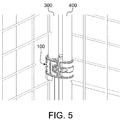
- the hinge body 100 includes a first profile portion 130, which is an arcuate section of the body which is configured to at least partially enclose a first profile 300 (cf. Fig. 5 ).
- the first profile 300 is a vertical frame member of the side wall section of a roll container.
- a second profile portion 140 of the hinge body 100 is shown in the right bottom corner of Fig. 1 .
- the second profile portion 140 opposes the first profile portion 130 and is also a similar arcuate section which is configured to at least partially enclose a second profile 400 (cf. Fig. 5 ).
- the second profile 400 is a vertical frame member of a door, for the roll container.
- the first and second profile portions 130, 140 are dimensioned such to form an enveloping outer surface for the contact between the hinge and the pivoted elements.
- first and second profile portions 130, 140 there is a solid, i.e. continuous, sound, outer portion 110 which is arranged to be on the outside of the joint created by the hinge.
- outer portion 110 therefore connects the first and second profile portions 130, 140 and creates a sound outer surface for the hinge body, whereby the solid outer portion 100 withstands great retraction upon closing movement of the hinge.
- the hinge body 100 has an inner portion 120 which connects the first and second profile portions 130, 140 on the inside of the joint.
- the inner portion 120 is therefore located on the inside of the hinge joint of the pivoted profiles, i.e. on the side having the smaller radius between hinged elements in closed position.
- the inner portion 120 is formed by joinable terminal ends 150, 160 of the first and second profile portions 130, 140.
- the free extensions of the enclosing sections of the hinge body 100 are configured to be joined on the inside of the joint for closing the hinge body 100.
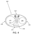
- a mating surface 200 is formed between said joined terminal ends 150, 160, whereby the outer portion 110 can be solid for withstanding retraction upon closing movement of the hinge ( Fig. 4 ).
- the terminal end 160 of the second profile portion 140 is configured to be joined with the outer portion 110 of the hinge body first for fully enclosing the second profile 400.
- Cooperating snap fit contours 111, 161 are preferably provided to the mating surfaces of the outer portion 110 and extension of the corresponding terminal end 160 for securing the second profile in the aperture 180 thus formed ( Fig. 2 ).
- the hinge body 100 may be attached to the second profile 400 with one hand without tools. Therefore said terminal end 160 is considered as the inner terminal end of the inner portion 120 of the hinge body 100.
- the inner terminal end 160 has an angled inward protruding extension which is adapted to engage with the inner surface of the outer portion 110 ( Figs. 2 and 3 ).
- the extension is shaped such that, when engaged to the outer portion 110, it together with the first and second profile portions 130, 140 defines apertures 170, 180 for enclosing the profiles. Therefore, as illustrated in Figs. 3 and 4 , the body 100 comprises two parallel apertures 170, 180 for receiving the profiles.
- the apertures 170, 180 are in other words separated by the extension of the inner terminal end 160.
- the terminal end 150 of the first profile portion 130 is configured to close the hinge body 100 by coupling to the terminal end 160 of the second profile portion 140.
- the terminal end 160 of the second profile portion 140 i.e. the inner terminal end
- the terminal end 150 of the first profile portion 130 i.e. the outer terminal end 150 is configured to attach to the outer surface of the inner terminal end 160.
- Cooperating snap fit contours 152, 162 are preferably provided to the mating surfaces of the joined terminal ends 150, 160 for securing the first profile in the aperture 170 thus formed ( Fig. 2 ).
- the hinge body 100 may be attached also to the first profile 300 with one hand without tools.
- the terminal ends 150, 160 have been provided with holes 153, 163 which are parallel to the apertures 170, 180 for the profiles.
- the holes 153, 163 are provided with corresponding parts of the terminal ends 150, 160 such that they are aligned when the body 100 is in closed position, i.e. when the terminal ends 150, 160 are joined.
- the through hole of the hinge body 100 formed by the consecutive holes 153, 163 enables the use of a torsion bar 500 ( Fig. 6 ) which may be inserted through the consecutive holes 153, 163 of the terminal ends 150, 160 to secure the terminal ends 150, 160 to each other, thus improving the torsional integrity of the hinge.
- a long torsion bar 500 may be used to join the superposed hinge bodies, which keeps the hinge bodies aligned and to some extent improves the torsional stiffness of the whole hinge assembly.
- the hinge body preferably includes a through hole 190 provided between the outer and inner portions 110, 120, wherein the hole 190 penetrates the joined terminal ends 150, 160 in a direction which is orthogonal to the axial direction of the apertures 170, 180 for profiles 300, 400.
- the through hole 190 provides a passage way for means for further securing the closed position of the hinge body 100.
- Said means may be established with a bolt and nut (as shown in Fig. 5 ), locking pin, a tie, such as a cable tie, or a similar fixing apparatus for securing the hinge body 100 into a closed position. Said means also hold the torsion bar 500 in place.
- Table 1 List of reference numbers.
- one-piece hinge body 110 outer portion 111 1 st snap fit contour: female 120 inner portion 130 1 st profile portion 140 2 nd profile portion 150 outer terminal end 152 2 nd snap fit contour: male 153 hole 160 inner terminal end 161 1 st snap fit contour: male 162 2 nd snap fit contour: female 163 hole 170 1 st profile aperture 180 2 nd profile aperture 190 hole for locking screw 200 mating surface 300 1 st profile 400 2 nd profile 500 torsion bar
Landscapes
- Engineering & Computer Science (AREA)
- Mechanical Engineering (AREA)
- Hinges (AREA)
- Pivots And Pivotal Connections (AREA)
Claims (7)
- Ein einstückiger Gelenkkörper (100), um zwei parallele Profile zu verschwenken, welcher Gelenkkörper (100) aufweist:- einen ersten Profilbereich (130), der eingerichtet ist um zumindest teilweise eine Öffnung (170) zum Umschließen eines ersten Profils zu definieren,- einen zweiten Profilbereich (140), der eingerichtet ist um zumindest teilweise eine weitere Öffnung (180) zum Umschließen eines zweiten Profils, das zu dem ersten Profil parallel ist, zu definieren,- einen äußeren Bereich (110), der die ersten und zweiten Profilbereiche (130, 140) verbindet und sich auf der Außenseite der Gelenkverbindung der schwenkenden Profile befindet, wobei der äußere Bereich (110) fest ist, um dem Rückzug nach der Schließbewegung des Gelenks zu widerstehen, und- einen dem äußeren Bereich gegenüberliegenden inneren Bereich (120), welcher die ersten und zweiten Profilbereiche (130, 140) verbindet und sich auf der Innenseite der Gelenkverbindung der schwenkenden Profile befindet,
wobei der innere Bereich (120) aus verbindbaren Abschlussenden (150, 160) der ersten und zweiten Profilbereiche (130, 140) besteht, wobei eine Fügefläche (200) zwischen den genannten verbundenen Abschlussenden (150, 160) gebildet wird,
dadurch gekennzeichnet, dass- eines der Abschlussenden (160) eine Verlängerung aufweist, die angepasst ist, um mit der inneren Oberfläche des äußeren Bereichs (110) einzugreifen und geformt ist, um Öffnungen (170, 180) zum Umschließen der Profile teilweise zu definieren, wobei der Körper (100) zwei parallele Öffnungen (170, 180) zur Aufnahme der Profile aufweist, welche Öffnungen (170, 180) durch die Verlängerung des genannten einen der Abschlussenden (160) getrennt sind,- das andere Abschlussende (150) angepasst ist, um den Körper (100) zu schließen, indem es mit dem Abschlussende (160) koppelt, das die genannte Verlängerung aufweist, und wobei- die Abschlussenden (150, 160) sich entsprechende Löcher (153, 163) aufweisen, welche:• parallel zu den Öffnungen (170, 180) für die Profile sind und welche• ausgerichtet sind, wenn der Körper (100) in der geschlossenen Position ist, d.h. die Abschlussenden (150, 160) verbunden sind, und welche• mittels eines durch die aufeinanderfolgenden Löcher (153, 163) der Abschlussenden (150, 160) eingefügten Torsionsstabes (500) an einander gesichert werden können. - Der einstückiger Gelenkkörper (100) nach Anspruch 1, wobei der einstückiger Gelenkkörper (100) aus einem elastischen Material besteht, wie etwa Polyamid oder Polypropylen, so dass- der Körper (100) sich öffnen lässt, um die Profile aufzunehmen, und sich schließen lasst, um die genannten Profile zu umschließen, und dass- ein Schiebesitz zwischen dem Gelenkkörper (100) und dem einen Querschnitt habenden Profil gebildet wird,wodurch ein Gelenk zwischen den genannten Profilen gebildet wird.
- Der einstückiger Gelenkkörper (100) nach Anspruch 1, wobei zusammenwirkende Schnappsitzkonturen (111, 161) an den Fügeflächen des äußeren Bereichs (110) bereitgestellt sind und somit die Verlängerung des entsprechenden Abschlussendes (160) zum Sichern des zweiten Profils in der Öffnung (180) gebildet wird.
- Der einstückiger Gelenkkörper (100) nach Anspruch 3, wobei zusammenwirkende Schnappsitzkonturen (152, 162) an den Fügeflächen der verbundenen Abschlussenden (150, 160) bereitgestellt sind, um das erste Profil in der somit gebildeten Öffnung (170) zu sichern.
- Der einstückiger Gelenkkörper (100) nach Anspruch 1,wobei der Körper (100) ein Durchgangsloch (190) aufweist, das zwischen den äußeren und inneren Bereichen (110, 120) bereitgestellt ist, wobei das Loch (190) die verbundenen Abschlussenden (150, 160) in einer Richtung orthogonal zu der axialen Richtung der Öffnungen (170, 180) für Profile durchdringt, um einen Durchgangsweg für Mittel zum weiteren Sichern der geschlossenen Position des Gelenkkörpers (100) bereitzustellen.
- Eine Gelenkbaugruppe, um zwei parallele Wandabschnittsprofile eines Logistikladungsträgers zu verschwenken, dadurch gekennzeichnet, dass die Baugruppe mittels mindestens eines Gelenkkörpers (100) nach Anspruch 1 gebildet wird.
- Eine Gelenkbaugruppe nach Anspruch 6, wobei die Baugruppe mindestens zwei Gelenkkörper (100) aufweist, die im Verhältnis zueinander derart überlagert sind, dass ein Torsionsstab (500) angeordnet ist, um die überlagerten Gelenkkörper (100) durch die ausgerichteten Torsionsstablöcher (153, 163) zu verbinden.
Priority Applications (6)
| Application Number | Priority Date | Filing Date | Title |
|---|---|---|---|
| EP12162920.8A EP2647785B1 (de) | 2012-04-03 | 2012-04-03 | Einteiliger Scharnierkörper und Scharnieranordnung für schwenkbare Elemente |
| ES12162920.8T ES2589005T3 (es) | 2012-04-03 | 2012-04-03 | Cuerpo de bisagra monopieza y conjunto de bisagra para hacer pivotar elementos |
| AU2013244865A AU2013244865B2 (en) | 2012-04-03 | 2013-03-14 | One-piece hinge body and hinge assembly for pivoting elements |
| US14/391,932 US9181738B2 (en) | 2012-04-03 | 2013-03-14 | One-piece hinge body and hinge assembly for pivoting elements |
| PCT/FI2013/050290 WO2013150179A1 (en) | 2012-04-03 | 2013-03-14 | One-piece hinge body and hinge assembly for pivoting elements |
| ZA2014/07094A ZA201407094B (en) | 2012-04-03 | 2014-09-30 | One-piece hinge body and hinge assembly for pivoting elements |
Applications Claiming Priority (1)
| Application Number | Priority Date | Filing Date | Title |
|---|---|---|---|
| EP12162920.8A EP2647785B1 (de) | 2012-04-03 | 2012-04-03 | Einteiliger Scharnierkörper und Scharnieranordnung für schwenkbare Elemente |
Publications (2)
| Publication Number | Publication Date |
|---|---|
| EP2647785A1 EP2647785A1 (de) | 2013-10-09 |
| EP2647785B1 true EP2647785B1 (de) | 2016-08-03 |
Family
ID=48095904
Family Applications (1)
| Application Number | Title | Priority Date | Filing Date |
|---|---|---|---|
| EP12162920.8A Active EP2647785B1 (de) | 2012-04-03 | 2012-04-03 | Einteiliger Scharnierkörper und Scharnieranordnung für schwenkbare Elemente |
Country Status (6)
| Country | Link |
|---|---|
| US (1) | US9181738B2 (de) |
| EP (1) | EP2647785B1 (de) |
| AU (1) | AU2013244865B2 (de) |
| ES (1) | ES2589005T3 (de) |
| WO (1) | WO2013150179A1 (de) |
| ZA (1) | ZA201407094B (de) |
Families Citing this family (3)
| Publication number | Priority date | Publication date | Assignee | Title |
|---|---|---|---|---|
| CN107939199A (zh) * | 2017-11-20 | 2018-04-20 | 平湖福达五金制品有限公司 | 一种可拆卸合页 |
| US11384576B2 (en) * | 2018-07-25 | 2022-07-12 | TransGard LLC | Hinge for maintaining posts in longitudinal contact |
| US12586489B2 (en) * | 2020-09-28 | 2026-03-24 | Kenneth LeRoy Thompson | Rail mount flagpole |
Family Cites Families (20)
| Publication number | Priority date | Publication date | Assignee | Title |
|---|---|---|---|---|
| US1232048A (en) * | 1916-10-11 | 1917-07-03 | Henry Kolkmeier | Gate-hinge. |
| US1261678A (en) * | 1916-12-26 | 1918-04-02 | John S Barnes | Gate-hinge. |
| US1793013A (en) * | 1929-01-30 | 1931-02-17 | William F Robertson | Hinge |
| US2651806A (en) * | 1951-10-10 | 1953-09-15 | John M Thompson | Adjustable gate hinge |
| DE3441302C1 (de) * | 1984-11-12 | 1986-04-10 | Guido, Jürgen, Dipl.-Ing., 8402 Neutraubling | Rohrschelle aus federelastischem Werkstoff |
| US4729149A (en) * | 1986-10-14 | 1988-03-08 | Hackney Wholesale | Gate hinge assembly |
| US5094578A (en) * | 1991-02-04 | 1992-03-10 | Master Industries, Inc. | Self-locking retainer clip |
| DE9107185U1 (de) * | 1991-06-11 | 1992-10-08 | Emhart Inc., Newark, Del. | Halter für längliche Gegenstände |
| ES2123204T3 (es) * | 1994-03-09 | 1999-01-01 | Bundy Int Ltd | Abrazadera para sujetar tuberias. |
| US5593143A (en) * | 1995-03-30 | 1997-01-14 | Ferrarin; James A. | Universal fence post connector |
| US5820048A (en) * | 1996-04-09 | 1998-10-13 | Illinois Tool Works Inc. | Side latching hinge mechanism |
| US6845970B1 (en) * | 2000-06-16 | 2005-01-25 | Gregory S. Kenton | Gate section and base for a safety rail system |
| GB0208181D0 (en) * | 2002-04-10 | 2002-05-22 | Bekaert Handling Ltd | Hinges |
| US6802106B2 (en) * | 2002-05-24 | 2004-10-12 | Edward Taglianetti | Clamp on adjustable male hinge |
| US6719363B2 (en) * | 2002-09-12 | 2004-04-13 | Collins & Aikman Products Co. | Hinge apparatus for vehicle floor systems |
| JP2009503375A (ja) * | 2005-07-20 | 2009-01-29 | ニューフレイ リミテッド ライアビリティ カンパニー | リテーナを有するヒンジ付クリップ |
| DE202005016085U1 (de) | 2005-10-11 | 2007-02-22 | Wanzl Metallwarenfabrik Gmbh | Transportcontainer |
| JP2007232063A (ja) * | 2006-02-28 | 2007-09-13 | Nippon Pop Rivets & Fasteners Ltd | パイプ等の防振保持具 |
| JP2008281169A (ja) * | 2007-05-14 | 2008-11-20 | Ykk Corp | 保持具 |
| US20120318935A1 (en) * | 2011-06-16 | 2012-12-20 | Benedetti Steven M | Multiple tube diameter retaining insert |
-
2012
- 2012-04-03 ES ES12162920.8T patent/ES2589005T3/es active Active
- 2012-04-03 EP EP12162920.8A patent/EP2647785B1/de active Active
-
2013
- 2013-03-14 US US14/391,932 patent/US9181738B2/en active Active
- 2013-03-14 WO PCT/FI2013/050290 patent/WO2013150179A1/en not_active Ceased
- 2013-03-14 AU AU2013244865A patent/AU2013244865B2/en active Active
-
2014
- 2014-09-30 ZA ZA2014/07094A patent/ZA201407094B/en unknown
Also Published As
| Publication number | Publication date |
|---|---|
| AU2013244865A1 (en) | 2014-10-16 |
| ZA201407094B (en) | 2016-05-25 |
| WO2013150179A1 (en) | 2013-10-10 |
| ES2589005T3 (es) | 2016-11-08 |
| US20150143665A1 (en) | 2015-05-28 |
| AU2013244865B2 (en) | 2015-10-29 |
| EP2647785A1 (de) | 2013-10-09 |
| US9181738B2 (en) | 2015-11-10 |
Similar Documents
| Publication | Publication Date | Title |
|---|---|---|
| US10952515B2 (en) | Item of luggage | |
| EP2647785B1 (de) | Einteiliger Scharnierkörper und Scharnieranordnung für schwenkbare Elemente | |
| KR101754192B1 (ko) | 접이식 컨테이너 | |
| US6216899B1 (en) | Dismountable container | |
| CA2960207C (en) | Mesh barrier assembly | |
| US20100202852A1 (en) | No-tools panel coupler and insert | |
| EP2996951B1 (de) | Transportbehälter mit sicherungsvorrichtung | |
| US9452881B2 (en) | Cargo locker with doors | |
| US6978595B2 (en) | Chain links and cable carrier chains containing same | |
| US20040144685A1 (en) | Two-piece interlocking corner protector | |
| US6807710B2 (en) | Hinges | |
| US20120131765A1 (en) | Hinge for transport cases, trunks, suitcases and the like | |
| CA2735616A1 (en) | Internally reinforced pneumatic carrier | |
| KR20210000863U (ko) | 철근 연결용 나사식 원터치 커플러 | |
| AU2012201480B2 (en) | Hinge Module, Hing Assembly And Roll Container | |
| US20120285851A1 (en) | Modular top frame | |
| KR20180055318A (ko) | 보안성이 강화된 포장상자 | |
| US20180050738A1 (en) | Pickup truck having a folding rail structure | |
| US20180127206A1 (en) | Structural member connection having improved structural support | |
| KR200471458Y1 (ko) | 파이프용 클램프 | |
| EP3318705B1 (de) | Tür, schliesssystem und logistikbehälter | |
| WO2024110212A1 (en) | Hinge, sleeve pack, and pallet container | |
| KR101399100B1 (ko) | 윙 바디 적재함용 바닥판 | |
| US11286106B1 (en) | Crate assembly | |
| EP3286097B2 (de) | Faltschachtel mit geschütztem verriegelungsmechanismus |
Legal Events
| Date | Code | Title | Description |
|---|---|---|---|
| PUAI | Public reference made under article 153(3) epc to a published international application that has entered the european phase |
Free format text: ORIGINAL CODE: 0009012 |
|
| AK | Designated contracting states |
Kind code of ref document: A1 Designated state(s): AL AT BE BG CH CY CZ DE DK EE ES FI FR GB GR HR HU IE IS IT LI LT LU LV MC MK MT NL NO PL PT RO RS SE SI SK SM TR |
|
| AX | Request for extension of the european patent |
Extension state: BA ME |
|
| 17P | Request for examination filed |
Effective date: 20140403 |
|
| RBV | Designated contracting states (corrected) |
Designated state(s): AL AT BE BG CH CY CZ DE DK EE ES FI FR GB GR HR HU IE IS IT LI LT LU LV MC MK MT NL NO PL PT RO RS SE SI SK SM TR |
|
| 17Q | First examination report despatched |
Effective date: 20150204 |
|
| GRAP | Despatch of communication of intention to grant a patent |
Free format text: ORIGINAL CODE: EPIDOSNIGR1 |
|
| INTG | Intention to grant announced |
Effective date: 20160321 |
|
| GRAS | Grant fee paid |
Free format text: ORIGINAL CODE: EPIDOSNIGR3 |
|
| GRAA | (expected) grant |
Free format text: ORIGINAL CODE: 0009210 |
|
| AK | Designated contracting states |
Kind code of ref document: B1 Designated state(s): AL AT BE BG CH CY CZ DE DK EE ES FI FR GB GR HR HU IE IS IT LI LT LU LV MC MK MT NL NO PL PT RO RS SE SI SK SM TR |
|
| REG | Reference to a national code |
Ref country code: GB Ref legal event code: FG4D |
|
| REG | Reference to a national code |
Ref country code: CH Ref legal event code: EP Ref country code: AT Ref legal event code: REF Ref document number: 817459 Country of ref document: AT Kind code of ref document: T Effective date: 20160815 |
|
| REG | Reference to a national code |
Ref country code: IE Ref legal event code: FG4D |
|
| REG | Reference to a national code |
Ref country code: DE Ref legal event code: R096 Ref document number: 602012021157 Country of ref document: DE |
|
| REG | Reference to a national code |
Ref country code: ES Ref legal event code: FG2A Ref document number: 2589005 Country of ref document: ES Kind code of ref document: T3 Effective date: 20161108 |
|
| REG | Reference to a national code |
Ref country code: NL Ref legal event code: MP Effective date: 20160803 |
|
| REG | Reference to a national code |
Ref country code: LT Ref legal event code: MG4D |
|
| REG | Reference to a national code |
Ref country code: AT Ref legal event code: MK05 Ref document number: 817459 Country of ref document: AT Kind code of ref document: T Effective date: 20160803 |
|
| PG25 | Lapsed in a contracting state [announced via postgrant information from national office to epo] |
Ref country code: FI Free format text: LAPSE BECAUSE OF FAILURE TO SUBMIT A TRANSLATION OF THE DESCRIPTION OR TO PAY THE FEE WITHIN THE PRESCRIBED TIME-LIMIT Effective date: 20160803 Ref country code: NL Free format text: LAPSE BECAUSE OF FAILURE TO SUBMIT A TRANSLATION OF THE DESCRIPTION OR TO PAY THE FEE WITHIN THE PRESCRIBED TIME-LIMIT Effective date: 20160803 Ref country code: RS Free format text: LAPSE BECAUSE OF FAILURE TO SUBMIT A TRANSLATION OF THE DESCRIPTION OR TO PAY THE FEE WITHIN THE PRESCRIBED TIME-LIMIT Effective date: 20160803 Ref country code: HR Free format text: LAPSE BECAUSE OF FAILURE TO SUBMIT A TRANSLATION OF THE DESCRIPTION OR TO PAY THE FEE WITHIN THE PRESCRIBED TIME-LIMIT Effective date: 20160803 Ref country code: IT Free format text: LAPSE BECAUSE OF FAILURE TO SUBMIT A TRANSLATION OF THE DESCRIPTION OR TO PAY THE FEE WITHIN THE PRESCRIBED TIME-LIMIT Effective date: 20160803 Ref country code: IS Free format text: LAPSE BECAUSE OF FAILURE TO SUBMIT A TRANSLATION OF THE DESCRIPTION OR TO PAY THE FEE WITHIN THE PRESCRIBED TIME-LIMIT Effective date: 20161203 Ref country code: NO Free format text: LAPSE BECAUSE OF FAILURE TO SUBMIT A TRANSLATION OF THE DESCRIPTION OR TO PAY THE FEE WITHIN THE PRESCRIBED TIME-LIMIT Effective date: 20161103 Ref country code: LT Free format text: LAPSE BECAUSE OF FAILURE TO SUBMIT A TRANSLATION OF THE DESCRIPTION OR TO PAY THE FEE WITHIN THE PRESCRIBED TIME-LIMIT Effective date: 20160803 |
|
| PG25 | Lapsed in a contracting state [announced via postgrant information from national office to epo] |
Ref country code: PT Free format text: LAPSE BECAUSE OF FAILURE TO SUBMIT A TRANSLATION OF THE DESCRIPTION OR TO PAY THE FEE WITHIN THE PRESCRIBED TIME-LIMIT Effective date: 20161205 Ref country code: SE Free format text: LAPSE BECAUSE OF FAILURE TO SUBMIT A TRANSLATION OF THE DESCRIPTION OR TO PAY THE FEE WITHIN THE PRESCRIBED TIME-LIMIT Effective date: 20160803 Ref country code: GR Free format text: LAPSE BECAUSE OF FAILURE TO SUBMIT A TRANSLATION OF THE DESCRIPTION OR TO PAY THE FEE WITHIN THE PRESCRIBED TIME-LIMIT Effective date: 20161104 Ref country code: AT Free format text: LAPSE BECAUSE OF FAILURE TO SUBMIT A TRANSLATION OF THE DESCRIPTION OR TO PAY THE FEE WITHIN THE PRESCRIBED TIME-LIMIT Effective date: 20160803 Ref country code: PL Free format text: LAPSE BECAUSE OF FAILURE TO SUBMIT A TRANSLATION OF THE DESCRIPTION OR TO PAY THE FEE WITHIN THE PRESCRIBED TIME-LIMIT Effective date: 20160803 Ref country code: LV Free format text: LAPSE BECAUSE OF FAILURE TO SUBMIT A TRANSLATION OF THE DESCRIPTION OR TO PAY THE FEE WITHIN THE PRESCRIBED TIME-LIMIT Effective date: 20160803 |
|
| REG | Reference to a national code |
Ref country code: FR Ref legal event code: PLFP Year of fee payment: 6 |
|
| PG25 | Lapsed in a contracting state [announced via postgrant information from national office to epo] |
Ref country code: EE Free format text: LAPSE BECAUSE OF FAILURE TO SUBMIT A TRANSLATION OF THE DESCRIPTION OR TO PAY THE FEE WITHIN THE PRESCRIBED TIME-LIMIT Effective date: 20160803 Ref country code: RO Free format text: LAPSE BECAUSE OF FAILURE TO SUBMIT A TRANSLATION OF THE DESCRIPTION OR TO PAY THE FEE WITHIN THE PRESCRIBED TIME-LIMIT Effective date: 20160803 |
|
| REG | Reference to a national code |
Ref country code: DE Ref legal event code: R097 Ref document number: 602012021157 Country of ref document: DE |
|
| PG25 | Lapsed in a contracting state [announced via postgrant information from national office to epo] |
Ref country code: DK Free format text: LAPSE BECAUSE OF FAILURE TO SUBMIT A TRANSLATION OF THE DESCRIPTION OR TO PAY THE FEE WITHIN THE PRESCRIBED TIME-LIMIT Effective date: 20160803 Ref country code: SK Free format text: LAPSE BECAUSE OF FAILURE TO SUBMIT A TRANSLATION OF THE DESCRIPTION OR TO PAY THE FEE WITHIN THE PRESCRIBED TIME-LIMIT Effective date: 20160803 Ref country code: BE Free format text: LAPSE BECAUSE OF FAILURE TO SUBMIT A TRANSLATION OF THE DESCRIPTION OR TO PAY THE FEE WITHIN THE PRESCRIBED TIME-LIMIT Effective date: 20160803 Ref country code: BG Free format text: LAPSE BECAUSE OF FAILURE TO SUBMIT A TRANSLATION OF THE DESCRIPTION OR TO PAY THE FEE WITHIN THE PRESCRIBED TIME-LIMIT Effective date: 20161103 Ref country code: SM Free format text: LAPSE BECAUSE OF FAILURE TO SUBMIT A TRANSLATION OF THE DESCRIPTION OR TO PAY THE FEE WITHIN THE PRESCRIBED TIME-LIMIT Effective date: 20160803 Ref country code: CZ Free format text: LAPSE BECAUSE OF FAILURE TO SUBMIT A TRANSLATION OF THE DESCRIPTION OR TO PAY THE FEE WITHIN THE PRESCRIBED TIME-LIMIT Effective date: 20160803 |
|
| PLBE | No opposition filed within time limit |
Free format text: ORIGINAL CODE: 0009261 |
|
| STAA | Information on the status of an ep patent application or granted ep patent |
Free format text: STATUS: NO OPPOSITION FILED WITHIN TIME LIMIT |
|
| 26N | No opposition filed |
Effective date: 20170504 |
|
| PG25 | Lapsed in a contracting state [announced via postgrant information from national office to epo] |
Ref country code: SI Free format text: LAPSE BECAUSE OF FAILURE TO SUBMIT A TRANSLATION OF THE DESCRIPTION OR TO PAY THE FEE WITHIN THE PRESCRIBED TIME-LIMIT Effective date: 20160803 |
|
| REG | Reference to a national code |
Ref country code: CH Ref legal event code: PL |
|
| REG | Reference to a national code |
Ref country code: IE Ref legal event code: MM4A |
|
| PG25 | Lapsed in a contracting state [announced via postgrant information from national office to epo] |
Ref country code: MC Free format text: LAPSE BECAUSE OF FAILURE TO SUBMIT A TRANSLATION OF THE DESCRIPTION OR TO PAY THE FEE WITHIN THE PRESCRIBED TIME-LIMIT Effective date: 20160803 |
|
| PG25 | Lapsed in a contracting state [announced via postgrant information from national office to epo] |
Ref country code: LU Free format text: LAPSE BECAUSE OF NON-PAYMENT OF DUE FEES Effective date: 20170403 Ref country code: LI Free format text: LAPSE BECAUSE OF NON-PAYMENT OF DUE FEES Effective date: 20170430 Ref country code: CH Free format text: LAPSE BECAUSE OF NON-PAYMENT OF DUE FEES Effective date: 20170430 |
|
| REG | Reference to a national code |
Ref country code: FR Ref legal event code: PLFP Year of fee payment: 7 |
|
| PG25 | Lapsed in a contracting state [announced via postgrant information from national office to epo] |
Ref country code: IE Free format text: LAPSE BECAUSE OF NON-PAYMENT OF DUE FEES Effective date: 20170403 |
|
| PG25 | Lapsed in a contracting state [announced via postgrant information from national office to epo] |
Ref country code: MT Free format text: LAPSE BECAUSE OF NON-PAYMENT OF DUE FEES Effective date: 20170403 |
|
| PG25 | Lapsed in a contracting state [announced via postgrant information from national office to epo] |
Ref country code: AL Free format text: LAPSE BECAUSE OF FAILURE TO SUBMIT A TRANSLATION OF THE DESCRIPTION OR TO PAY THE FEE WITHIN THE PRESCRIBED TIME-LIMIT Effective date: 20160803 |
|
| PG25 | Lapsed in a contracting state [announced via postgrant information from national office to epo] |
Ref country code: HU Free format text: LAPSE BECAUSE OF FAILURE TO SUBMIT A TRANSLATION OF THE DESCRIPTION OR TO PAY THE FEE WITHIN THE PRESCRIBED TIME-LIMIT; INVALID AB INITIO Effective date: 20120403 |
|
| PG25 | Lapsed in a contracting state [announced via postgrant information from national office to epo] |
Ref country code: CY Free format text: LAPSE BECAUSE OF NON-PAYMENT OF DUE FEES Effective date: 20160803 |
|
| PG25 | Lapsed in a contracting state [announced via postgrant information from national office to epo] |
Ref country code: MK Free format text: LAPSE BECAUSE OF FAILURE TO SUBMIT A TRANSLATION OF THE DESCRIPTION OR TO PAY THE FEE WITHIN THE PRESCRIBED TIME-LIMIT Effective date: 20160803 |
|
| PG25 | Lapsed in a contracting state [announced via postgrant information from national office to epo] |
Ref country code: TR Free format text: LAPSE BECAUSE OF FAILURE TO SUBMIT A TRANSLATION OF THE DESCRIPTION OR TO PAY THE FEE WITHIN THE PRESCRIBED TIME-LIMIT Effective date: 20160803 |
|
| PGFP | Annual fee paid to national office [announced via postgrant information from national office to epo] |
Ref country code: DE Payment date: 20250402 Year of fee payment: 14 |
|
| PGFP | Annual fee paid to national office [announced via postgrant information from national office to epo] |
Ref country code: GB Payment date: 20250411 Year of fee payment: 14 |
|
| PGFP | Annual fee paid to national office [announced via postgrant information from national office to epo] |
Ref country code: FR Payment date: 20250411 Year of fee payment: 14 |
|
| PGFP | Annual fee paid to national office [announced via postgrant information from national office to epo] |
Ref country code: ES Payment date: 20250714 Year of fee payment: 14 |