EP2647852A2 - Rondelle - Google Patents
Rondelle Download PDFInfo
- Publication number
- EP2647852A2 EP2647852A2 EP13401029.7A EP13401029A EP2647852A2 EP 2647852 A2 EP2647852 A2 EP 2647852A2 EP 13401029 A EP13401029 A EP 13401029A EP 2647852 A2 EP2647852 A2 EP 2647852A2
- Authority
- EP
- European Patent Office
- Prior art keywords
- washer
- paint
- painted
- components
- protecting coating
- Prior art date
- Legal status (The legal status is an assumption and is not a legal conclusion. Google has not performed a legal analysis and makes no representation as to the accuracy of the status listed.)
- Withdrawn
Links
Images

Classifications
-
- F—MECHANICAL ENGINEERING; LIGHTING; HEATING; WEAPONS; BLASTING
- F16—ENGINEERING ELEMENTS AND UNITS; GENERAL MEASURES FOR PRODUCING AND MAINTAINING EFFECTIVE FUNCTIONING OF MACHINES OR INSTALLATIONS; THERMAL INSULATION IN GENERAL
- F16B—DEVICES FOR FASTENING OR SECURING CONSTRUCTIONAL ELEMENTS OR MACHINE PARTS TOGETHER, e.g. NAILS, BOLTS, CIRCLIPS, CLAMPS, CLIPS OR WEDGES; JOINTS OR JOINTING
- F16B43/00—Washers or equivalent devices; Other devices for supporting bolt-heads or nuts
Definitions
- the invention relates to a washer according to the preamble of claim 1.
- Such washers are known in many ways.
- a lacquer-protecting coating is present on the side facing the painted component of the washer.
- This coating consists for example of a flat rubber disc.
- This rubber disc is glued to the actual washer made of steel. The rubber disc can not be positioned sufficiently precisely to the holes in the components, so that the screws which engage through the holes damage the lacquer layer at least in the holes or in their edge region.
- large surface pressures occur at the edges of the holes, which are penetrated by the screws for connecting the components, so that the paint layer flakes off there.
- the invention has for its object to provide washers available that painted components without the risk of damage to the paint layer can be connected together.
- the washer and thus the components to be connected by cross-bolts are positioned by the annular projection in the region of the holes so that the paint layer is not damaged.
- the dimensions of the outer diameter of the annular projection and the inner diameter of the lacquer layer coated with a hole wall of the hole are matched accordingly.
- the outer diameter of the lug is by no means larger than the inner diameter of the hole provided with a lacquer layer.
- a particularly advantageous lacquer-protecting coating with a sufficiently high strength of the coating is obtained by the lacquer-protecting coating of the washer consisting of polyamide.
- the coating can be attached to the steel disc as a basic body in a simpler manner by means of a plastic injection or production process.
- a particularly paint-sparing embodiment results from the fact that the paint-protecting coating is additionally mounted on the wall of the hole in the washer.
- the main body of the washer made of stainless steel.
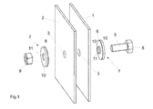
- plates 1 and 2 which may be, for example, the upper surface 1 of a reservoir of an agricultural device, in particular a distributor and the lower surface 2 of a mounted thereon attachment container to increase the capacity of the reservoir, are provided for corrosion protection with a lacquer layer.
- holes 2 are mounted in the plates 1, 2, wherein the hole wall 4 is provided with a lacquer layer.
- the holes 3 are penetrated by the screw 5 for connecting the two painted plates 6 of the screw 5 with each other.
- the washer 7 is arranged with a paint-protecting coating 8.
- a washer 7 with a paint-protecting coating 8 between the nut 9, the on the screw thread of the screw 5 is turned on, and the adjacent surface of the painted plate 2 is arranged.
- the main body 10 of the washers 7 is made of stainless steel.
- the lacquer-protecting coating 8 of the washers 7 has an annular projection 12 in the region of the through-hole 11 of the washers 7.
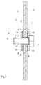
- This annular projection 12 is designed such that, after placement on the plates 12, in the region of the hole 3 of the plates 1, 2 to be joined in the respective hole 3 of the component to be connected 1, 2 almost.
- the paint-protecting coating 8 of the washer 7 has a in the respective hole 3 of the component to be connected 1, 2 summarizing annular projection 12, such as Fig. 2 shows.
- the paint-protecting coating 8 is additionally mounted on the wall of the hole 11 in the washers 7, such as Fig. 4 shows.
- the paint-protecting coating 8 of the washers 7 is made of polyamide.
- the lacquer-protecting coating 8 made of polyamide, a paint-preserving assembly and connection of the two components 1, 2 is achieved with each other, so that no lacquer damage to the lacquer layer of the painted panels 1, 2 in the region of the connecting hole in the region of the joint by the screw 5 and the washers 7 3, through which the screw 5 engages, arises.
- the washer 7 and thus the components to be connected 1, 2 sweeping screws 5 are positioned by the annular projection 12 in the holes 3, that the lacquer layer is not damaged.
- the dimensions of the outer diameter of the annular projection 12 and the inner diameter of the coated with a paint layer hole wall of the hole 3 matched accordingly.
- the outer diameter is by no means greater than the inner diameter of the hole 3 provided with a lacquer layer.
Landscapes
- Engineering & Computer Science (AREA)
- General Engineering & Computer Science (AREA)
- Mechanical Engineering (AREA)
- Bolts, Nuts, And Washers (AREA)
- Connection Of Plates (AREA)
- Details Or Accessories Of Spraying Plant Or Apparatus (AREA)
Applications Claiming Priority (1)
| Application Number | Priority Date | Filing Date | Title |
|---|---|---|---|
| DE102012102926A DE102012102926A1 (de) | 2012-04-04 | 2012-04-04 | Unterlegscheibe |
Publications (2)
| Publication Number | Publication Date |
|---|---|
| EP2647852A2 true EP2647852A2 (fr) | 2013-10-09 |
| EP2647852A3 EP2647852A3 (fr) | 2017-07-26 |
Family
ID=48190449
Family Applications (1)
| Application Number | Title | Priority Date | Filing Date |
|---|---|---|---|
| EP13401029.7A Withdrawn EP2647852A3 (fr) | 2012-04-04 | 2013-03-26 | Rondelle |
Country Status (2)
| Country | Link |
|---|---|
| EP (1) | EP2647852A3 (fr) |
| DE (1) | DE102012102926A1 (fr) |
Cited By (1)
| Publication number | Priority date | Publication date | Assignee | Title |
|---|---|---|---|---|
| DE102017119010A1 (de) | 2017-08-21 | 2019-02-21 | Amazonen-Werke H. Dreyer Gmbh & Co. Kg | Befestigungseinheit |
Families Citing this family (1)
| Publication number | Priority date | Publication date | Assignee | Title |
|---|---|---|---|---|
| DE102014007674A1 (de) | 2014-05-27 | 2015-12-03 | Thaletec Gmbh | Unterlegscheibe |
Family Cites Families (9)
| Publication number | Priority date | Publication date | Assignee | Title |
|---|---|---|---|---|
| BE511895A (fr) * | 1951-06-05 | |||
| GB759233A (en) * | 1954-10-30 | 1956-10-17 | A Marrel Ets | Improvements in seals for hydraulic rams |
| JPH0810702Y2 (ja) * | 1990-11-06 | 1996-03-29 | 旭電化工業株式会社 | 水膨潤性ゴム付座金 |
| JP2711485B2 (ja) * | 1991-04-02 | 1998-02-10 | 内山工業株式会社 | ワッシヤーシール |
| US6435791B1 (en) * | 2000-05-19 | 2002-08-20 | Maclean-Fogg Company | Wheel fastener assemblies |
| DE20210703U1 (de) * | 2002-07-11 | 2003-11-20 | Metallwarenfabrik Hermann Winker GmbH & Co. KG, 78549 Spaichingen | Dichtungsscheibe und damit versehene Dichtungsmutter |
| DE202005003149U1 (de) * | 2005-02-24 | 2005-05-19 | Kienmoser, Hermann | Unterlegscheibe |
| US20060239797A1 (en) * | 2005-04-20 | 2006-10-26 | Evanbar Michael S | Pre-formed elastomeric fastener adhesive device and method of installation |
| DE112007002817B4 (de) * | 2006-11-27 | 2021-07-08 | Uchiyama Manufacturing Corp. | Ringförmige Metalldichtung |
-
2012
- 2012-04-04 DE DE102012102926A patent/DE102012102926A1/de not_active Withdrawn
-
2013
- 2013-03-26 EP EP13401029.7A patent/EP2647852A3/fr not_active Withdrawn
Non-Patent Citations (1)
| Title |
|---|
| None |
Cited By (3)
| Publication number | Priority date | Publication date | Assignee | Title |
|---|---|---|---|---|
| DE102017119010A1 (de) | 2017-08-21 | 2019-02-21 | Amazonen-Werke H. Dreyer Gmbh & Co. Kg | Befestigungseinheit |
| WO2019038163A1 (fr) | 2017-08-21 | 2019-02-28 | Amazonen-Werke H. Dreyer Gmbh & Co. Kg | Unité de fixation |
| US11555514B2 (en) | 2017-08-21 | 2023-01-17 | Amazonen-Werke H. Dreyer SE & Co. KG | Attachment unit |
Also Published As
| Publication number | Publication date |
|---|---|
| DE102012102926A1 (de) | 2013-10-10 |
| EP2647852A3 (fr) | 2017-07-26 |
Similar Documents
| Publication | Publication Date | Title |
|---|---|---|
| EP2182225B1 (fr) | Boulons filetés | |
| DE2157124B2 (de) | Koptschraube mit Unterlegscheibe | |
| WO2011141020A1 (fr) | Écrou cage électriquement isolant | |
| EP1426637A1 (fr) | Ecrou de roue | |
| DE102015217383A1 (de) | Masseanschluss für ein Aluminiumbauteil | |
| WO2008095593A1 (fr) | Tête de vis à tête fraisée | |
| DE102015100658A1 (de) | Anordnung mit einem schraubbaren Befestigungselement und einem Dichtelement | |
| EP2647852A2 (fr) | Rondelle | |
| DE202015006861U1 (de) | Schutzprofilsystem | |
| DE3329967A1 (de) | Schraub- oder nietverbindung | |
| EP2871116B1 (fr) | Pièce de formage pour véhicules automobiles | |
| DE102006012761A1 (de) | Befestigungsanordnung für wenigstens einen Kabelschuh an einem Schweißbolzen | |
| DE102008019852A1 (de) | Befestigungsanordnung für mehrere Ringkabelschuhe an einem Schweißbolzen | |
| EP2088645B1 (fr) | Système de fixation | |
| DE102007056748A1 (de) | Bremsscheiben/Nabenverbindung | |
| AT509228B1 (de) | Schutzvorrichtung | |
| DE102017204197A1 (de) | Massebolzen für ein Kraftfahrzeug | |
| DE202019106638U1 (de) | Verbindungselement für Mehrkantrohre | |
| EP1841998A1 (fr) | Dispositif permettant de raccorder un tuyau souple de maniere etanche aux fluides | |
| DE202013105939U1 (de) | D-förmiges Schraubverbindungsbauteil für Möbelverbindungen | |
| DE102013214759A1 (de) | Fahrzeugkarosseriebauteil aus faserverstärktem Kunststoff | |
| DE202005007661U1 (de) | Halteeinrichtung sowie Halteelement hierfür | |
| DE202013104650U1 (de) | Düse, insbesondere für Bohrwerkzeug mit zugehörigem Montagewerkzeug | |
| DE6923043U (de) | Kopfschraube fuer moebelschlaege mit einem in einer bohrung eines moebelteiles drehbar gelagerten anzugsglied | |
| DE7435870U (de) | Anschluß- oder Verschlußstopfen für Radiatoren |
Legal Events
| Date | Code | Title | Description |
|---|---|---|---|
| PUAI | Public reference made under article 153(3) epc to a published international application that has entered the european phase |
Free format text: ORIGINAL CODE: 0009012 |
|
| AK | Designated contracting states |
Kind code of ref document: A2 Designated state(s): AL AT BE BG CH CY CZ DE DK EE ES FI FR GB GR HR HU IE IS IT LI LT LU LV MC MK MT NL NO PL PT RO RS SE SI SK SM TR |
|
| AX | Request for extension of the european patent |
Extension state: BA ME |
|
| PUAL | Search report despatched |
Free format text: ORIGINAL CODE: 0009013 |
|
| AK | Designated contracting states |
Kind code of ref document: A3 Designated state(s): AL AT BE BG CH CY CZ DE DK EE ES FI FR GB GR HR HU IE IS IT LI LT LU LV MC MK MT NL NO PL PT RO RS SE SI SK SM TR |
|
| AX | Request for extension of the european patent |
Extension state: BA ME |
|
| RIC1 | Information provided on ipc code assigned before grant |
Ipc: F16B 43/00 20060101AFI20170616BHEP |
|
| STAA | Information on the status of an ep patent application or granted ep patent |
Free format text: STATUS: THE APPLICATION IS DEEMED TO BE WITHDRAWN |
|
| 18D | Application deemed to be withdrawn |
Effective date: 20180127 |