EP2647860A2 - Douille à raccorder à un composant - Google Patents
Douille à raccorder à un composant Download PDFInfo
- Publication number
- EP2647860A2 EP2647860A2 EP13001552.2A EP13001552A EP2647860A2 EP 2647860 A2 EP2647860 A2 EP 2647860A2 EP 13001552 A EP13001552 A EP 13001552A EP 2647860 A2 EP2647860 A2 EP 2647860A2
- Authority
- EP
- European Patent Office
- Prior art keywords
- socket
- component
- locking means
- positive locking
- positive
- Prior art date
- Legal status (The legal status is an assumption and is not a legal conclusion. Google has not performed a legal analysis and makes no representation as to the accuracy of the status listed.)
- Granted
Links
Images
Classifications
-
- F—MECHANICAL ENGINEERING; LIGHTING; HEATING; WEAPONS; BLASTING
- F16—ENGINEERING ELEMENTS AND UNITS; GENERAL MEASURES FOR PRODUCING AND MAINTAINING EFFECTIVE FUNCTIONING OF MACHINES OR INSTALLATIONS; THERMAL INSULATION IN GENERAL
- F16L—PIPES; JOINTS OR FITTINGS FOR PIPES; SUPPORTS FOR PIPES, CABLES OR PROTECTIVE TUBING; MEANS FOR THERMAL INSULATION IN GENERAL
- F16L5/00—Devices for use where pipes, cables or protective tubing pass through walls or partitions
-
- B—PERFORMING OPERATIONS; TRANSPORTING
- B21—MECHANICAL METAL-WORKING WITHOUT ESSENTIALLY REMOVING MATERIAL; PUNCHING METAL
- B21K—MAKING FORGED OR PRESSED METAL PRODUCTS, e.g. HORSE-SHOES, RIVETS, BOLTS OR WHEELS
- B21K25/00—Uniting components to form integral members, e.g. turbine wheels and shafts, caulks with inserts, with or without shaping of the components
-
- B—PERFORMING OPERATIONS; TRANSPORTING
- B23—MACHINE TOOLS; METAL-WORKING NOT OTHERWISE PROVIDED FOR
- B23P—METAL-WORKING NOT OTHERWISE PROVIDED FOR; COMBINED OPERATIONS; UNIVERSAL MACHINE TOOLS
- B23P11/00—Connecting or disconnecting metal parts or objects by metal-working techniques not otherwise provided for
- B23P11/005—Connecting or disconnecting metal parts or objects by metal-working techniques not otherwise provided for by expanding or crimping
-
- F—MECHANICAL ENGINEERING; LIGHTING; HEATING; WEAPONS; BLASTING
- F16—ENGINEERING ELEMENTS AND UNITS; GENERAL MEASURES FOR PRODUCING AND MAINTAINING EFFECTIVE FUNCTIONING OF MACHINES OR INSTALLATIONS; THERMAL INSULATION IN GENERAL
- F16B—DEVICES FOR FASTENING OR SECURING CONSTRUCTIONAL ELEMENTS OR MACHINE PARTS TOGETHER, e.g. NAILS, BOLTS, CIRCLIPS, CLAMPS, CLIPS OR WEDGES; JOINTS OR JOINTING
- F16B17/00—Connecting constructional elements or machine parts by a part of or on one member entering a hole in the other and involving plastic deformation
- F16B17/006—Connecting constructional elements or machine parts by a part of or on one member entering a hole in the other and involving plastic deformation of rods or tubes to sheets or plates
-
- F—MECHANICAL ENGINEERING; LIGHTING; HEATING; WEAPONS; BLASTING
- F16—ENGINEERING ELEMENTS AND UNITS; GENERAL MEASURES FOR PRODUCING AND MAINTAINING EFFECTIVE FUNCTIONING OF MACHINES OR INSTALLATIONS; THERMAL INSULATION IN GENERAL
- F16C—SHAFTS; FLEXIBLE SHAFTS; ELEMENTS OR CRANKSHAFT MECHANISMS; ROTARY BODIES OTHER THAN GEARING ELEMENTS; BEARINGS
- F16C33/00—Parts of bearings; Special methods for making bearings or parts thereof
- F16C33/02—Parts of sliding-contact bearings
- F16C33/04—Brasses; Bushes; Linings
- F16C33/06—Sliding surface mainly made of metal
- F16C33/08—Attachment of brasses, bushes or linings to the bearing housing
-
- F—MECHANICAL ENGINEERING; LIGHTING; HEATING; WEAPONS; BLASTING
- F16—ENGINEERING ELEMENTS AND UNITS; GENERAL MEASURES FOR PRODUCING AND MAINTAINING EFFECTIVE FUNCTIONING OF MACHINES OR INSTALLATIONS; THERMAL INSULATION IN GENERAL
- F16C—SHAFTS; FLEXIBLE SHAFTS; ELEMENTS OR CRANKSHAFT MECHANISMS; ROTARY BODIES OTHER THAN GEARING ELEMENTS; BEARINGS
- F16C35/00—Rigid support of bearing units; Housings, e.g. caps, covers
- F16C35/02—Rigid support of bearing units; Housings, e.g. caps, covers in the case of sliding-contact bearings
-
- F—MECHANICAL ENGINEERING; LIGHTING; HEATING; WEAPONS; BLASTING
- F16—ENGINEERING ELEMENTS AND UNITS; GENERAL MEASURES FOR PRODUCING AND MAINTAINING EFFECTIVE FUNCTIONING OF MACHINES OR INSTALLATIONS; THERMAL INSULATION IN GENERAL
- F16L—PIPES; JOINTS OR FITTINGS FOR PIPES; SUPPORTS FOR PIPES, CABLES OR PROTECTIVE TUBING; MEANS FOR THERMAL INSULATION IN GENERAL
- F16L5/00—Devices for use where pipes, cables or protective tubing pass through walls or partitions
- F16L5/02—Sealing
- F16L5/10—Sealing by using sealing rings or sleeves only
-
- F—MECHANICAL ENGINEERING; LIGHTING; HEATING; WEAPONS; BLASTING
- F16—ENGINEERING ELEMENTS AND UNITS; GENERAL MEASURES FOR PRODUCING AND MAINTAINING EFFECTIVE FUNCTIONING OF MACHINES OR INSTALLATIONS; THERMAL INSULATION IN GENERAL
- F16C—SHAFTS; FLEXIBLE SHAFTS; ELEMENTS OR CRANKSHAFT MECHANISMS; ROTARY BODIES OTHER THAN GEARING ELEMENTS; BEARINGS
- F16C2226/00—Joining parts; Fastening; Assembling or mounting parts
- F16C2226/50—Positive connections
- F16C2226/52—Positive connections with plastic deformation, e.g. caulking or staking
-
- F—MECHANICAL ENGINEERING; LIGHTING; HEATING; WEAPONS; BLASTING
- F16—ENGINEERING ELEMENTS AND UNITS; GENERAL MEASURES FOR PRODUCING AND MAINTAINING EFFECTIVE FUNCTIONING OF MACHINES OR INSTALLATIONS; THERMAL INSULATION IN GENERAL
- F16C—SHAFTS; FLEXIBLE SHAFTS; ELEMENTS OR CRANKSHAFT MECHANISMS; ROTARY BODIES OTHER THAN GEARING ELEMENTS; BEARINGS
- F16C2300/00—Application independent of particular apparatuses
- F16C2300/02—General use or purpose, i.e. no use, purpose, special adaptation or modification indicated or a wide variety of uses mentioned
-
- Y—GENERAL TAGGING OF NEW TECHNOLOGICAL DEVELOPMENTS; GENERAL TAGGING OF CROSS-SECTIONAL TECHNOLOGIES SPANNING OVER SEVERAL SECTIONS OF THE IPC; TECHNICAL SUBJECTS COVERED BY FORMER USPC CROSS-REFERENCE ART COLLECTIONS [XRACs] AND DIGESTS
- Y10—TECHNICAL SUBJECTS COVERED BY FORMER USPC
- Y10T—TECHNICAL SUBJECTS COVERED BY FORMER US CLASSIFICATION
- Y10T29/00—Metal working
- Y10T29/49—Method of mechanical manufacture
- Y10T29/49995—Shaping one-piece blank by removing material
Definitions
- the invention relates to a socket for coupling with a component and to a method for avoiding relative movement between the socket and the component coupled to the socket.
- the sockets can be inserted in a component or placed on a component.
- the attachment of the jacks to the components should be such that there is no relative movement between the sleeve and the component.
- a relative movement between the bush and the component can be caused by swelling or changing loads on the bushing and / or the component.
- Bushings that move at the joint lead very often to increased wear at the joint or, when using corrosive materials, to increased corrosion at the joint.
- Various methods are already known by means of which the joining force between the bush and the component is increased in order to prevent the aforementioned relative movement.
- bushings are thermally inserted for wear protection or corrosion protection of components.
- the joining force is limited due to the technical limitations in the temperature difference between the sleeve and the component before joining.
- a disadvantage of the thermal joining method is that the achievable joining force is not sufficient to reliably prevent turning or wandering of the bushing during prolonged swelling or changing load action during operation.
- the socket can be glued to the component.
- only slight joining forces can be achieved with this fastening method, so that the field of application of the fastening method remains limited to applications of the bush, in which no high loads act on them.
- the object of the invention is to provide a socket which does not have at least the aforementioned disadvantages. It is also an object to provide a method for avoiding relative movement between the bushing and the component, which does not have at least the aforementioned disadvantages.
- a bush in particular a bearing bush, which can be coupled to a component and has at least one interlocking means.
- the at least one positive locking means is formed integrally with the bush and may be made of the same material as the bushing. This is the Positive locking means produced by editing the socket.
- the positive-locking means is deformed, in particular deformed, and brought into positive engagement with the component.
- Such a bushing has the advantage that due to the positive connection between the bushing and the component, the risk of relative movement between the bush and the component due to swelling or changing loads is significantly reduced.
- the joining force between the bush and the component increases, so that bushing migration is prevented.
- the interlocking means can be easily manufactured without providing a hydraulic device.
- the positive locking means can be produced on the socket by means of a Einstemmvons or a rolling-in process.
- a puncturing method is understood to mean a method in which the interlocking means is produced by a caulking tool.
- Einstemm compiler a simultaneous deformation of the socket, in particular the positive locking means, can be realized on the entire circumference.
- a rolling-in method is understood as meaning such a method, in which the positive-locking means is produced by a rolling-in tool.
- the socket may comprise a socket body and a head portion which extends transversely, in particular vertically, from the socket body.
- the positive locking means may be formed integrally with the socket body and / or the head portion.
- the interlocking means may be provided at an end remote from the head portion of the socket body.
- the head portion may be formed integrally with the socket body.
- the socket Before processing the socket, in particular a production of the positive locking means, the socket can be placed on a component or inserted into a component. This offers the advantage that after the machining process and the deformation process, in particular a plastic deformation process, such as. the deformation of the positive locking means, no further steps are necessary.
- a groove can be formed in the socket.
- a side facing away from the head portion of the socket can be chamfered.
- the chamfering can take place on a side facing away from the component.
- the groove can be produced on an end face of the bushing.
- the positive locking means may be formed as a protruding portion.
- the interlocking means may be formed as a projecting from the socket body and / or from the head portion section.
- a counter-form-fitting recess can be generated, in which the positive locking means can penetrate. This offers the advantage that the risk of a relative movement between the bushing and the component is further reduced.
- the same machining device and / or the same tool can be used.
- the processing device serves, among other things, to hold the tool. This offers the advantage that the manufacturing process of the positive locking means on the bushing is done quickly and thus cost.
- the manufacturing process of the positive locking means on the bushing is done quickly and thus cost.
- a force can be exerted on the positive locking means in the direction of the component by the tool.
- the socket can be placed on a component or inserted into a component.
- the socket which is applied to a component such as e.g. a pin, mandrel, shank or the like, is placed on, as an external socket and the socket which is inserted into a component, referred to as the internal socket.
- the deformation direction of the form-fitting part depends on whether the socket is an external or internal socket. In both cases, the positive locking means is deformed in each case in the direction of the component, in particular bent.
- the sockets can be made of different materials and can be used for a variety of purposes, e.g. for wear protection, corrosion protection or repair of load application points or attachment points between different components.
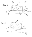
- socket 2 according to a first embodiment is coupled to a component 1.
- the bush 2 is partly inserted into a recess 11 of the component 1.
- the socket 2 has a head portion 21 and a socket body 20.
- the head portion 21 extends substantially perpendicularly from the socket body 20 and is in contact with the component 1.
- the socket body 20 is also in contact with the component 1.
- the socket 2 has at its end facing away from the head portion 21 two positive locking means in the form of two protruding portions 23, 23 '.
- the two Positive locking means are separated by a groove 22 and protrude from the socket body 20.
- the groove 22 extends from the end face of the bushing 2 in the direction of the head portion 21.
- the bushing body 20 is regarded as the part of the bushing 2 which is not machined, ie the part in which no material removal occurred during the production of the groove 22 ,
- a recess 10 is provided, which is counter-shaped to the positive locking means or to the protruding portion 23, 23 '.
- FIG. 1 shown a state in which no deformation of the protruding portion 23, 23 'takes place.
- the bushing 2 can still move in a longitudinal direction P of the bushing 2, wherein the movement in the longitudinal direction P is directed opposite to the movement in the longitudinal direction P '.
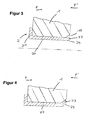
- FIG. 2 a state is shown in which a deformation of the positive locking means is carried out.
- the interlocking means or the component 1 closer to the protruding portion 23 is formed such that it penetrates into the recess 10 and comes into contact with the component 1.
- a positive connection between the sleeve 2 and the component 1 is achieved by the forming.
- FIGS. 3 and 4 a socket 1 according to a second embodiment is shown. It will be in FIG. 3 a state shown in which the positive locking means is not deformed and in FIG. 4 a state in which the positive locking means is deformed.
- the sleeve 2 according to the second embodiment differs from the sleeve 2 according to the first embodiment in the configuration of the positive locking means.
- only a single positive locking means in the form of a projecting from the female body 20 portion 23 is formed.
- the interlocking means is formed by chamfering a side of the socket 2 remote from the head portion.
- the side of the bushing 2 which is provided at the end remote from the head section 21 and at a side of the bushing body 20 remote from the component 1 is chamfered.
- the positive-locking means projects from the socket body 20.
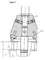
- FIG. 5 a processing apparatus for carrying out the curling process is shown.
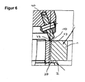
- FIG. 6 an enlarged portion of the engagement portion of the device tool with the socket is shown.
- the processing device has a carrier 3 for supporting the socket 2 and the component 1.
- the processing device has a tool holder 4, which holds a tool 40.
- the tool 40 can rotate about an axis of rotation as well as perform a lifting movement along a longitudinal axis of the processing device.
- the tool holder may be a pillar drill.
- the recess 10 is generated before the coupling process with the socket 2. This can be done by the in FIG. 5 shown processing device or another device done. Subsequently, a coupling of the socket 2 with the component 1. For this purpose, the socket 2 is inserted into the recess 11 of the component. After insertion, the groove 22 and thus the positive locking means in the socket 2 is generated by means of the tool 40.
Landscapes
- Engineering & Computer Science (AREA)
- General Engineering & Computer Science (AREA)
- Mechanical Engineering (AREA)
- Automatic Assembly (AREA)
- Connector Housings Or Holding Contact Members (AREA)
- Mutual Connection Of Rods And Tubes (AREA)
- Connection Of Plates (AREA)
Applications Claiming Priority (1)
| Application Number | Priority Date | Filing Date | Title |
|---|---|---|---|
| DE102012007010A DE102012007010A1 (de) | 2012-04-05 | 2012-04-05 | Buchse zum Koppeln mit einem Bauteil |
Publications (3)
| Publication Number | Publication Date |
|---|---|
| EP2647860A2 true EP2647860A2 (fr) | 2013-10-09 |
| EP2647860A3 EP2647860A3 (fr) | 2017-12-27 |
| EP2647860B1 EP2647860B1 (fr) | 2023-12-06 |
Family
ID=48087338
Family Applications (1)
| Application Number | Title | Priority Date | Filing Date |
|---|---|---|---|
| EP13001552.2A Active EP2647860B1 (fr) | 2012-04-05 | 2013-03-26 | Douille à raccorder à un composant |
Country Status (4)
| Country | Link |
|---|---|
| US (1) | US9366363B2 (fr) |
| EP (1) | EP2647860B1 (fr) |
| CN (1) | CN103362918B (fr) |
| DE (1) | DE102012007010A1 (fr) |
Families Citing this family (2)
| Publication number | Priority date | Publication date | Assignee | Title |
|---|---|---|---|---|
| DE102013223005A1 (de) | 2013-11-12 | 2015-05-13 | Brose Fahrzeugteile Gmbh & Co. Kg, Coburg | Verfahren zum Verbinden einer Buchse mit einem Bauteil |
| DE102023136189A1 (de) * | 2023-12-21 | 2025-06-26 | Arnold Umformtechnik Gmbh & Co. Kg | Verbindungselement, Anordnung und Verfahren |
Family Cites Families (24)
| Publication number | Priority date | Publication date | Assignee | Title |
|---|---|---|---|---|
| US914705A (en) * | 1908-01-28 | 1909-03-09 | Frank A Donnelly | Eyelet. |
| US1226090A (en) * | 1917-03-31 | 1917-05-15 | Nat Bush Company | Bushing for bungs. |
| US1297142A (en) * | 1918-07-19 | 1919-03-11 | William J Gibbons | Bushing-blank and process of making bushings. |
| US1481217A (en) * | 1921-11-21 | 1924-01-15 | Richard E Maloy | Grommet |
| US2327656A (en) * | 1942-04-13 | 1943-08-24 | Buckeye Forging Company | Container |
| US2385294A (en) * | 1944-06-17 | 1945-09-18 | New York Engineering Company | Bung bushing |
| US2583719A (en) * | 1946-05-10 | 1952-01-29 | Weatherhead Co | Grommet |
| US2901800A (en) * | 1953-09-10 | 1959-09-01 | C E M Company | Self coring grommet |
| GB991487A (en) * | 1961-10-10 | 1965-05-12 | Multifastener Corp | Nut and panel assembly and method of making same |
| US3399435A (en) * | 1966-12-28 | 1968-09-03 | United Shoe Machinery Corp | Grommet assembly |
| GB2190435B (en) * | 1986-05-08 | 1989-12-06 | Johnson Electric Ind Mfg | Sintered bearings |
| JPH0324889Y2 (fr) * | 1986-06-09 | 1991-05-30 | ||
| DE19609252C1 (de) * | 1996-02-28 | 1997-01-16 | Brose Fahrzeugteile | Bauteilverbindung sowie Verfahren und Vorrichtung zu ihrer Herstellung |
| DE19950719B4 (de) * | 1999-10-21 | 2008-05-21 | Volkswagen Ag | Arbeitsverfahren zur Herstellung einer Nietverbindung sowie Niet, Nietwerkzeug und Anwendung derselben |
| US6817079B2 (en) * | 2002-11-20 | 2004-11-16 | Falcon Fasteners Reg'd | Method of riveting a headed fastener |
| JP2005034857A (ja) * | 2003-07-17 | 2005-02-10 | Aisin Seiki Co Ltd | カシメ部材およびカシメ方法 |
| TWI226921B (en) * | 2003-09-16 | 2005-01-21 | Benq Corp | Bushing structure |
| US7380315B1 (en) * | 2003-11-04 | 2008-06-03 | In-Soo Jung | Systems and methods for reinforcing lockable telescoping poles |
| DE102005007203A1 (de) * | 2004-10-15 | 2006-04-20 | Gustav Klauke Gmbh | Kabelschuh mit Mutter bzw. Funktionsteil, Verfahren zur Herstellung eines solchen Kabelschuhs und Mutter |
| DE202005005827U1 (de) * | 2005-04-11 | 2005-06-16 | Igus Gmbh | Gleitlager und Gleitlagersystem |
| EP1717460A1 (fr) * | 2005-04-27 | 2006-11-02 | Richard Bergner Verbindungstechnik GmbH & Co. KG | Unité de construction avec un élément enfoncé d'insertion aussi bien que l'élément et la procédure d'insertion pour serrer un élément d'insertion dedans |
| US8037578B2 (en) * | 2007-06-04 | 2011-10-18 | Hewlett-Packard Development Company, L.P. | Low-profile assemblies |
| US8225478B2 (en) * | 2008-01-30 | 2012-07-24 | The Boeing Company | Memory shape bushings and bearings |
| CN102338147A (zh) * | 2011-09-14 | 2012-02-01 | 苏州工业园区新凯精密五金有限公司 | 一种带有锥度斜齿的螺母结构 |
-
2012
- 2012-04-05 DE DE102012007010A patent/DE102012007010A1/de active Pending
-
2013
- 2013-03-26 EP EP13001552.2A patent/EP2647860B1/fr active Active
- 2013-04-02 CN CN201310112411.5A patent/CN103362918B/zh active Active
- 2013-04-04 US US13/856,767 patent/US9366363B2/en active Active
Non-Patent Citations (1)
| Title |
|---|
| None |
Also Published As
| Publication number | Publication date |
|---|---|
| CN103362918B (zh) | 2017-03-01 |
| US9366363B2 (en) | 2016-06-14 |
| EP2647860B1 (fr) | 2023-12-06 |
| EP2647860A3 (fr) | 2017-12-27 |
| CN103362918A (zh) | 2013-10-23 |
| DE102012007010A1 (de) | 2013-10-10 |
| US20140150205A1 (en) | 2014-06-05 |
Similar Documents
| Publication | Publication Date | Title |
|---|---|---|
| EP1233193B1 (fr) | Tige à bague de serrage pour l'obtention d'une liaison mécanique solide de deux pièces ou plus rendue étanche par une masse de produit | |
| DE1932039A1 (de) | Zweiteiliges Verbindungselement Zweiteiliges Verbindungselement | |
| DE2537584A1 (de) | Selbstkalibrierende befestigungsanordnung | |
| EP2857699A1 (fr) | Douille taraudée à visser | |
| WO2008049731A1 (fr) | Disposition d'un boulon dans un perçage et procédé pour positionner et bloquer le boulon dans le perçage | |
| EP2860407A1 (fr) | Composant de structure | |
| EP4118717A1 (fr) | Connecteur à soudure de friction et son procédé de production | |
| DE19753111A1 (de) | Lagerbuchse mit Mittelbund sowie deren Verwendung und Herstellungsverfahren | |
| EP1336767B1 (fr) | Dispositif de couplage pour bras pourvu d'un porte-outil de construction modulaire | |
| EP2745980A1 (fr) | Procédé d'assemblage thermique d'éléments fonctionnels non circulaires sur un arbre | |
| EP2647860A2 (fr) | Douille à raccorder à un composant | |
| DE102011089079A1 (de) | Verfahren zum Herstellen eines Linearschienensystems und Kombinationsprodukt eines Linearschienensystems | |
| DE102007008142B4 (de) | Verfahren und Vorrichtungen zur Herstellung eines Mehrflächengleitlagers | |
| WO2011160241A1 (fr) | Procédé de réalisation d'un moletage intérieur dans un perçage de réception d'un corps de moyeu | |
| EP2446980A2 (fr) | Tuyau et procédé destinés au traitement d'extrémités de tuyaux | |
| DE102007007890A1 (de) | Verbindung von einer Innenwelle mit einer Aussenhülse bzw. einer Aussenwelle mit einer Innenhülse | |
| EP1729371B1 (fr) | Douille et son procédé fabrication | |
| EP2833007A1 (fr) | Liaison rotative | |
| EP3410546A1 (fr) | Procédé de fabrication d'un élément de contact pour un connecteur enfichable | |
| DE102012202331A1 (de) | Buchse zur Lochverstärkung in einem Bauteil | |
| DE102006033279A1 (de) | Verfahren und Vorrichtung zum Verbinden mehrerer Kabel mit einem Bauteil sowie Nietbuchse hierfür | |
| DE102014109752B4 (de) | Verfahren zur Montage einer verstellbaren Nockenwelle | |
| DE102013002190A1 (de) | Schraubanordnung | |
| DE102019109921A1 (de) | Verfahren zur Schaffung einer Pressverbindungsanordnung, Pressverbindungsanordnung und Verfahren zur Schaffung einer Spannverbindung sowie die Spannverbindung an sich sowie deren Verwendung | |
| EP3924578B1 (fr) | Cylindre de fermeture programmable |
Legal Events
| Date | Code | Title | Description |
|---|---|---|---|
| PUAI | Public reference made under article 153(3) epc to a published international application that has entered the european phase |
Free format text: ORIGINAL CODE: 0009012 |
|
| AK | Designated contracting states |
Kind code of ref document: A2 Designated state(s): AL AT BE BG CH CY CZ DE DK EE ES FI FR GB GR HR HU IE IS IT LI LT LU LV MC MK MT NL NO PL PT RO RS SE SI SK SM TR |
|
| AX | Request for extension of the european patent |
Extension state: BA ME |
|
| PUAL | Search report despatched |
Free format text: ORIGINAL CODE: 0009013 |
|
| AK | Designated contracting states |
Kind code of ref document: A3 Designated state(s): AL AT BE BG CH CY CZ DE DK EE ES FI FR GB GR HR HU IE IS IT LI LT LU LV MC MK MT NL NO PL PT RO RS SE SI SK SM TR |
|
| AX | Request for extension of the european patent |
Extension state: BA ME |
|
| RIC1 | Information provided on ipc code assigned before grant |
Ipc: F16C 33/08 20060101ALI20171117BHEP Ipc: B23P 11/00 20060101ALI20171117BHEP Ipc: F16C 35/02 20060101AFI20171117BHEP |
|
| STAA | Information on the status of an ep patent application or granted ep patent |
Free format text: STATUS: REQUEST FOR EXAMINATION WAS MADE |
|
| 17P | Request for examination filed |
Effective date: 20180621 |
|
| STAA | Information on the status of an ep patent application or granted ep patent |
Free format text: STATUS: EXAMINATION IS IN PROGRESS |
|
| 17Q | First examination report despatched |
Effective date: 20211203 |
|
| RIC1 | Information provided on ipc code assigned before grant |
Ipc: F16B 19/10 20060101ALN20230725BHEP Ipc: B21J 15/04 20060101ALN20230725BHEP Ipc: B23P 11/00 20060101ALI20230725BHEP Ipc: F16C 33/08 20060101ALI20230725BHEP Ipc: F16C 35/02 20060101AFI20230725BHEP |
|
| GRAP | Despatch of communication of intention to grant a patent |
Free format text: ORIGINAL CODE: EPIDOSNIGR1 |
|
| STAA | Information on the status of an ep patent application or granted ep patent |
Free format text: STATUS: GRANT OF PATENT IS INTENDED |
|
| RIC1 | Information provided on ipc code assigned before grant |
Ipc: F16B 19/10 20060101ALN20230830BHEP Ipc: B21J 15/04 20060101ALN20230830BHEP Ipc: B23P 11/00 20060101ALI20230830BHEP Ipc: F16C 33/08 20060101ALI20230830BHEP Ipc: F16C 35/02 20060101AFI20230830BHEP |
|
| INTG | Intention to grant announced |
Effective date: 20230913 |
|
| GRAS | Grant fee paid |
Free format text: ORIGINAL CODE: EPIDOSNIGR3 |
|
| GRAA | (expected) grant |
Free format text: ORIGINAL CODE: 0009210 |
|
| STAA | Information on the status of an ep patent application or granted ep patent |
Free format text: STATUS: THE PATENT HAS BEEN GRANTED |
|
| AK | Designated contracting states |
Kind code of ref document: B1 Designated state(s): AL AT BE BG CH CY CZ DE DK EE ES FI FR GB GR HR HU IE IS IT LI LT LU LV MC MK MT NL NO PL PT RO RS SE SI SK SM TR |
|
| REG | Reference to a national code |
Ref country code: GB Ref legal event code: FG4D Free format text: NOT ENGLISH |
|
| REG | Reference to a national code |
Ref country code: DE Ref legal event code: R096 Ref document number: 502013016471 Country of ref document: DE |
|
| REG | Reference to a national code |
Ref country code: CH Ref legal event code: EP |
|
| REG | Reference to a national code |
Ref country code: IE Ref legal event code: FG4D Free format text: LANGUAGE OF EP DOCUMENT: GERMAN |
|
| REG | Reference to a national code |
Ref country code: LT Ref legal event code: MG9D |
|
| PG25 | Lapsed in a contracting state [announced via postgrant information from national office to epo] |
Ref country code: GR Free format text: LAPSE BECAUSE OF FAILURE TO SUBMIT A TRANSLATION OF THE DESCRIPTION OR TO PAY THE FEE WITHIN THE PRESCRIBED TIME-LIMIT Effective date: 20240307 |
|
| REG | Reference to a national code |
Ref country code: NL Ref legal event code: MP Effective date: 20231206 |
|
| PG25 | Lapsed in a contracting state [announced via postgrant information from national office to epo] |
Ref country code: LT Free format text: LAPSE BECAUSE OF FAILURE TO SUBMIT A TRANSLATION OF THE DESCRIPTION OR TO PAY THE FEE WITHIN THE PRESCRIBED TIME-LIMIT Effective date: 20231206 |
|
| PG25 | Lapsed in a contracting state [announced via postgrant information from national office to epo] |
Ref country code: ES Free format text: LAPSE BECAUSE OF FAILURE TO SUBMIT A TRANSLATION OF THE DESCRIPTION OR TO PAY THE FEE WITHIN THE PRESCRIBED TIME-LIMIT Effective date: 20231206 |
|
| PG25 | Lapsed in a contracting state [announced via postgrant information from national office to epo] |
Ref country code: LT Free format text: LAPSE BECAUSE OF FAILURE TO SUBMIT A TRANSLATION OF THE DESCRIPTION OR TO PAY THE FEE WITHIN THE PRESCRIBED TIME-LIMIT Effective date: 20231206 Ref country code: GR Free format text: LAPSE BECAUSE OF FAILURE TO SUBMIT A TRANSLATION OF THE DESCRIPTION OR TO PAY THE FEE WITHIN THE PRESCRIBED TIME-LIMIT Effective date: 20240307 Ref country code: ES Free format text: LAPSE BECAUSE OF FAILURE TO SUBMIT A TRANSLATION OF THE DESCRIPTION OR TO PAY THE FEE WITHIN THE PRESCRIBED TIME-LIMIT Effective date: 20231206 Ref country code: BG Free format text: LAPSE BECAUSE OF FAILURE TO SUBMIT A TRANSLATION OF THE DESCRIPTION OR TO PAY THE FEE WITHIN THE PRESCRIBED TIME-LIMIT Effective date: 20240306 |
|
| PG25 | Lapsed in a contracting state [announced via postgrant information from national office to epo] |
Ref country code: NL Free format text: LAPSE BECAUSE OF FAILURE TO SUBMIT A TRANSLATION OF THE DESCRIPTION OR TO PAY THE FEE WITHIN THE PRESCRIBED TIME-LIMIT Effective date: 20231206 |
|
| PG25 | Lapsed in a contracting state [announced via postgrant information from national office to epo] |
Ref country code: SE Free format text: LAPSE BECAUSE OF FAILURE TO SUBMIT A TRANSLATION OF THE DESCRIPTION OR TO PAY THE FEE WITHIN THE PRESCRIBED TIME-LIMIT Effective date: 20231206 Ref country code: RS Free format text: LAPSE BECAUSE OF FAILURE TO SUBMIT A TRANSLATION OF THE DESCRIPTION OR TO PAY THE FEE WITHIN THE PRESCRIBED TIME-LIMIT Effective date: 20231206 Ref country code: NO Free format text: LAPSE BECAUSE OF FAILURE TO SUBMIT A TRANSLATION OF THE DESCRIPTION OR TO PAY THE FEE WITHIN THE PRESCRIBED TIME-LIMIT Effective date: 20240306 Ref country code: NL Free format text: LAPSE BECAUSE OF FAILURE TO SUBMIT A TRANSLATION OF THE DESCRIPTION OR TO PAY THE FEE WITHIN THE PRESCRIBED TIME-LIMIT Effective date: 20231206 Ref country code: LV Free format text: LAPSE BECAUSE OF FAILURE TO SUBMIT A TRANSLATION OF THE DESCRIPTION OR TO PAY THE FEE WITHIN THE PRESCRIBED TIME-LIMIT Effective date: 20231206 Ref country code: HR Free format text: LAPSE BECAUSE OF FAILURE TO SUBMIT A TRANSLATION OF THE DESCRIPTION OR TO PAY THE FEE WITHIN THE PRESCRIBED TIME-LIMIT Effective date: 20231206 |
|
| PG25 | Lapsed in a contracting state [announced via postgrant information from national office to epo] |
Ref country code: IS Free format text: LAPSE BECAUSE OF FAILURE TO SUBMIT A TRANSLATION OF THE DESCRIPTION OR TO PAY THE FEE WITHIN THE PRESCRIBED TIME-LIMIT Effective date: 20240406 |
|
| PG25 | Lapsed in a contracting state [announced via postgrant information from national office to epo] |
Ref country code: CZ Free format text: LAPSE BECAUSE OF FAILURE TO SUBMIT A TRANSLATION OF THE DESCRIPTION OR TO PAY THE FEE WITHIN THE PRESCRIBED TIME-LIMIT Effective date: 20231206 |
|
| PG25 | Lapsed in a contracting state [announced via postgrant information from national office to epo] |
Ref country code: SK Free format text: LAPSE BECAUSE OF FAILURE TO SUBMIT A TRANSLATION OF THE DESCRIPTION OR TO PAY THE FEE WITHIN THE PRESCRIBED TIME-LIMIT Effective date: 20231206 |
|
| PG25 | Lapsed in a contracting state [announced via postgrant information from national office to epo] |
Ref country code: SM Free format text: LAPSE BECAUSE OF FAILURE TO SUBMIT A TRANSLATION OF THE DESCRIPTION OR TO PAY THE FEE WITHIN THE PRESCRIBED TIME-LIMIT Effective date: 20231206 Ref country code: SK Free format text: LAPSE BECAUSE OF FAILURE TO SUBMIT A TRANSLATION OF THE DESCRIPTION OR TO PAY THE FEE WITHIN THE PRESCRIBED TIME-LIMIT Effective date: 20231206 Ref country code: RO Free format text: LAPSE BECAUSE OF FAILURE TO SUBMIT A TRANSLATION OF THE DESCRIPTION OR TO PAY THE FEE WITHIN THE PRESCRIBED TIME-LIMIT Effective date: 20231206 Ref country code: IT Free format text: LAPSE BECAUSE OF FAILURE TO SUBMIT A TRANSLATION OF THE DESCRIPTION OR TO PAY THE FEE WITHIN THE PRESCRIBED TIME-LIMIT Effective date: 20231206 Ref country code: IS Free format text: LAPSE BECAUSE OF FAILURE TO SUBMIT A TRANSLATION OF THE DESCRIPTION OR TO PAY THE FEE WITHIN THE PRESCRIBED TIME-LIMIT Effective date: 20240406 Ref country code: EE Free format text: LAPSE BECAUSE OF FAILURE TO SUBMIT A TRANSLATION OF THE DESCRIPTION OR TO PAY THE FEE WITHIN THE PRESCRIBED TIME-LIMIT Effective date: 20231206 Ref country code: CZ Free format text: LAPSE BECAUSE OF FAILURE TO SUBMIT A TRANSLATION OF THE DESCRIPTION OR TO PAY THE FEE WITHIN THE PRESCRIBED TIME-LIMIT Effective date: 20231206 |
|
| PG25 | Lapsed in a contracting state [announced via postgrant information from national office to epo] |
Ref country code: PL Free format text: LAPSE BECAUSE OF FAILURE TO SUBMIT A TRANSLATION OF THE DESCRIPTION OR TO PAY THE FEE WITHIN THE PRESCRIBED TIME-LIMIT Effective date: 20231206 Ref country code: PT Free format text: LAPSE BECAUSE OF FAILURE TO SUBMIT A TRANSLATION OF THE DESCRIPTION OR TO PAY THE FEE WITHIN THE PRESCRIBED TIME-LIMIT Effective date: 20240408 |
|
| PG25 | Lapsed in a contracting state [announced via postgrant information from national office to epo] |
Ref country code: PT Free format text: LAPSE BECAUSE OF FAILURE TO SUBMIT A TRANSLATION OF THE DESCRIPTION OR TO PAY THE FEE WITHIN THE PRESCRIBED TIME-LIMIT Effective date: 20240408 Ref country code: PL Free format text: LAPSE BECAUSE OF FAILURE TO SUBMIT A TRANSLATION OF THE DESCRIPTION OR TO PAY THE FEE WITHIN THE PRESCRIBED TIME-LIMIT Effective date: 20231206 |
|
| REG | Reference to a national code |
Ref country code: DE Ref legal event code: R097 Ref document number: 502013016471 Country of ref document: DE |
|
| PG25 | Lapsed in a contracting state [announced via postgrant information from national office to epo] |
Ref country code: DK Free format text: LAPSE BECAUSE OF FAILURE TO SUBMIT A TRANSLATION OF THE DESCRIPTION OR TO PAY THE FEE WITHIN THE PRESCRIBED TIME-LIMIT Effective date: 20231206 |
|
| PLBE | No opposition filed within time limit |
Free format text: ORIGINAL CODE: 0009261 |
|
| STAA | Information on the status of an ep patent application or granted ep patent |
Free format text: STATUS: NO OPPOSITION FILED WITHIN TIME LIMIT |
|
| PG25 | Lapsed in a contracting state [announced via postgrant information from national office to epo] |
Ref country code: SI Free format text: LAPSE BECAUSE OF FAILURE TO SUBMIT A TRANSLATION OF THE DESCRIPTION OR TO PAY THE FEE WITHIN THE PRESCRIBED TIME-LIMIT Effective date: 20231206 |
|
| PG25 | Lapsed in a contracting state [announced via postgrant information from national office to epo] |
Ref country code: SI Free format text: LAPSE BECAUSE OF FAILURE TO SUBMIT A TRANSLATION OF THE DESCRIPTION OR TO PAY THE FEE WITHIN THE PRESCRIBED TIME-LIMIT Effective date: 20231206 Ref country code: DK Free format text: LAPSE BECAUSE OF FAILURE TO SUBMIT A TRANSLATION OF THE DESCRIPTION OR TO PAY THE FEE WITHIN THE PRESCRIBED TIME-LIMIT Effective date: 20231206 |
|
| REG | Reference to a national code |
Ref country code: CH Ref legal event code: PL |
|
| 26N | No opposition filed |
Effective date: 20240909 |
|
| PG25 | Lapsed in a contracting state [announced via postgrant information from national office to epo] |
Ref country code: LU Free format text: LAPSE BECAUSE OF NON-PAYMENT OF DUE FEES Effective date: 20240326 |
|
| PG25 | Lapsed in a contracting state [announced via postgrant information from national office to epo] |
Ref country code: MC Free format text: LAPSE BECAUSE OF FAILURE TO SUBMIT A TRANSLATION OF THE DESCRIPTION OR TO PAY THE FEE WITHIN THE PRESCRIBED TIME-LIMIT Effective date: 20231206 |
|
| PG25 | Lapsed in a contracting state [announced via postgrant information from national office to epo] |
Ref country code: MC Free format text: LAPSE BECAUSE OF FAILURE TO SUBMIT A TRANSLATION OF THE DESCRIPTION OR TO PAY THE FEE WITHIN THE PRESCRIBED TIME-LIMIT Effective date: 20231206 Ref country code: LU Free format text: LAPSE BECAUSE OF NON-PAYMENT OF DUE FEES Effective date: 20240326 |
|
| REG | Reference to a national code |
Ref country code: BE Ref legal event code: MM Effective date: 20240331 |
|
| PG25 | Lapsed in a contracting state [announced via postgrant information from national office to epo] |
Ref country code: BE Free format text: LAPSE BECAUSE OF NON-PAYMENT OF DUE FEES Effective date: 20240331 |
|
| PG25 | Lapsed in a contracting state [announced via postgrant information from national office to epo] |
Ref country code: IE Free format text: LAPSE BECAUSE OF NON-PAYMENT OF DUE FEES Effective date: 20240326 |
|
| PG25 | Lapsed in a contracting state [announced via postgrant information from national office to epo] |
Ref country code: IE Free format text: LAPSE BECAUSE OF NON-PAYMENT OF DUE FEES Effective date: 20240326 Ref country code: BE Free format text: LAPSE BECAUSE OF NON-PAYMENT OF DUE FEES Effective date: 20240331 Ref country code: CH Free format text: LAPSE BECAUSE OF NON-PAYMENT OF DUE FEES Effective date: 20240331 |
|
| PGFP | Annual fee paid to national office [announced via postgrant information from national office to epo] |
Ref country code: DE Payment date: 20250331 Year of fee payment: 13 |
|
| REG | Reference to a national code |
Ref country code: AT Ref legal event code: MM01 Ref document number: 1638672 Country of ref document: AT Kind code of ref document: T Effective date: 20240326 |
|
| PG25 | Lapsed in a contracting state [announced via postgrant information from national office to epo] |
Ref country code: AT Free format text: LAPSE BECAUSE OF NON-PAYMENT OF DUE FEES Effective date: 20240326 |
|
| PG25 | Lapsed in a contracting state [announced via postgrant information from national office to epo] |
Ref country code: CY Free format text: LAPSE BECAUSE OF FAILURE TO SUBMIT A TRANSLATION OF THE DESCRIPTION OR TO PAY THE FEE WITHIN THE PRESCRIBED TIME-LIMIT; INVALID AB INITIO Effective date: 20130326 |
|
| PG25 | Lapsed in a contracting state [announced via postgrant information from national office to epo] |
Ref country code: HU Free format text: LAPSE BECAUSE OF FAILURE TO SUBMIT A TRANSLATION OF THE DESCRIPTION OR TO PAY THE FEE WITHIN THE PRESCRIBED TIME-LIMIT; INVALID AB INITIO Effective date: 20130326 |
|
| PG25 | Lapsed in a contracting state [announced via postgrant information from national office to epo] |
Ref country code: FI Free format text: LAPSE BECAUSE OF FAILURE TO SUBMIT A TRANSLATION OF THE DESCRIPTION OR TO PAY THE FEE WITHIN THE PRESCRIBED TIME-LIMIT Effective date: 20231207 |
|
| PG25 | Lapsed in a contracting state [announced via postgrant information from national office to epo] |
Ref country code: TR Free format text: LAPSE BECAUSE OF FAILURE TO SUBMIT A TRANSLATION OF THE DESCRIPTION OR TO PAY THE FEE WITHIN THE PRESCRIBED TIME-LIMIT Effective date: 20231206 |
|
| PGFP | Annual fee paid to national office [announced via postgrant information from national office to epo] |
Ref country code: GB Payment date: 20260330 Year of fee payment: 14 |
|
| PGFP | Annual fee paid to national office [announced via postgrant information from national office to epo] |
Ref country code: FR Payment date: 20260330 Year of fee payment: 14 |