EP2647862A2 - Kohlenstoff-keramik-bremsscheibe und herstellungsverfahren dafür - Google Patents
Kohlenstoff-keramik-bremsscheibe und herstellungsverfahren dafür Download PDFInfo
- Publication number
- EP2647862A2 EP2647862A2 EP11844022.1A EP11844022A EP2647862A2 EP 2647862 A2 EP2647862 A2 EP 2647862A2 EP 11844022 A EP11844022 A EP 11844022A EP 2647862 A2 EP2647862 A2 EP 2647862A2
- Authority
- EP
- European Patent Office
- Prior art keywords
- disk
- core
- carbon
- layer
- mold
- Prior art date
- Legal status (The legal status is an assumption and is not a legal conclusion. Google has not performed a legal analysis and makes no representation as to the accuracy of the status listed.)
- Granted
Links
Images



Classifications
-
- C—CHEMISTRY; METALLURGY
- C22—METALLURGY; FERROUS OR NON-FERROUS ALLOYS; TREATMENT OF ALLOYS OR NON-FERROUS METALS
- C22C—ALLOYS
- C22C49/00—Alloys containing metallic or non-metallic fibres or filaments
- C22C49/14—Alloys containing metallic or non-metallic fibres or filaments characterised by the fibres or filaments
-
- C—CHEMISTRY; METALLURGY
- C04—CEMENTS; CONCRETE; ARTIFICIAL STONE; CERAMICS; REFRACTORIES
- C04B—LIME, MAGNESIA; SLAG; CEMENTS; COMPOSITIONS THEREOF, e.g. MORTARS, CONCRETE OR LIKE BUILDING MATERIALS; ARTIFICIAL STONE; CERAMICS; REFRACTORIES; TREATMENT OF NATURAL STONE
- C04B35/00—Shaped ceramic products characterised by their composition; Ceramics compositions; Processing powders of inorganic compounds preparatory to the manufacturing of ceramic products
- C04B35/515—Shaped ceramic products characterised by their composition; Ceramics compositions; Processing powders of inorganic compounds preparatory to the manufacturing of ceramic products based on non-oxide ceramics
- C04B35/56—Shaped ceramic products characterised by their composition; Ceramics compositions; Processing powders of inorganic compounds preparatory to the manufacturing of ceramic products based on non-oxide ceramics based on carbides or oxycarbides
- C04B35/565—Shaped ceramic products characterised by their composition; Ceramics compositions; Processing powders of inorganic compounds preparatory to the manufacturing of ceramic products based on non-oxide ceramics based on carbides or oxycarbides based on silicon carbide
- C04B35/573—Shaped ceramic products characterised by their composition; Ceramics compositions; Processing powders of inorganic compounds preparatory to the manufacturing of ceramic products based on non-oxide ceramics based on carbides or oxycarbides based on silicon carbide obtained by reaction sintering or recrystallisation
-
- C—CHEMISTRY; METALLURGY
- C04—CEMENTS; CONCRETE; ARTIFICIAL STONE; CERAMICS; REFRACTORIES
- C04B—LIME, MAGNESIA; SLAG; CEMENTS; COMPOSITIONS THEREOF, e.g. MORTARS, CONCRETE OR LIKE BUILDING MATERIALS; ARTIFICIAL STONE; CERAMICS; REFRACTORIES; TREATMENT OF NATURAL STONE
- C04B35/00—Shaped ceramic products characterised by their composition; Ceramics compositions; Processing powders of inorganic compounds preparatory to the manufacturing of ceramic products
- C04B35/71—Ceramic products containing macroscopic reinforcing agents
- C04B35/78—Ceramic products containing macroscopic reinforcing agents containing non-metallic materials
- C04B35/80—Fibres, filaments, whiskers, platelets, or the like
- C04B35/83—Carbon fibres in a carbon matrix
-
- F—MECHANICAL ENGINEERING; LIGHTING; HEATING; WEAPONS; BLASTING
- F16—ENGINEERING ELEMENTS AND UNITS; GENERAL MEASURES FOR PRODUCING AND MAINTAINING EFFECTIVE FUNCTIONING OF MACHINES OR INSTALLATIONS; THERMAL INSULATION IN GENERAL
- F16D—COUPLINGS FOR TRANSMITTING ROTATION; CLUTCHES; BRAKES
- F16D65/00—Parts or details
- F16D65/02—Braking members; Mounting thereof
- F16D65/12—Discs; Drums for disc brakes
-
- C—CHEMISTRY; METALLURGY
- C04—CEMENTS; CONCRETE; ARTIFICIAL STONE; CERAMICS; REFRACTORIES
- C04B—LIME, MAGNESIA; SLAG; CEMENTS; COMPOSITIONS THEREOF, e.g. MORTARS, CONCRETE OR LIKE BUILDING MATERIALS; ARTIFICIAL STONE; CERAMICS; REFRACTORIES; TREATMENT OF NATURAL STONE
- C04B2235/00—Aspects relating to ceramic starting mixtures or sintered ceramic products
- C04B2235/02—Composition of constituents of the starting material or of secondary phases of the final product
- C04B2235/30—Constituents and secondary phases not being of a fibrous nature
- C04B2235/42—Non metallic elements added as constituents or additives, e.g. sulfur, phosphor, selenium or tellurium
- C04B2235/428—Silicon
-
- C—CHEMISTRY; METALLURGY
- C04—CEMENTS; CONCRETE; ARTIFICIAL STONE; CERAMICS; REFRACTORIES
- C04B—LIME, MAGNESIA; SLAG; CEMENTS; COMPOSITIONS THEREOF, e.g. MORTARS, CONCRETE OR LIKE BUILDING MATERIALS; ARTIFICIAL STONE; CERAMICS; REFRACTORIES; TREATMENT OF NATURAL STONE
- C04B2235/00—Aspects relating to ceramic starting mixtures or sintered ceramic products
- C04B2235/02—Composition of constituents of the starting material or of secondary phases of the final product
- C04B2235/30—Constituents and secondary phases not being of a fibrous nature
- C04B2235/48—Organic compounds becoming part of a ceramic after heat treatment, e.g. carbonising phenol resins
-
- C—CHEMISTRY; METALLURGY
- C04—CEMENTS; CONCRETE; ARTIFICIAL STONE; CERAMICS; REFRACTORIES
- C04B—LIME, MAGNESIA; SLAG; CEMENTS; COMPOSITIONS THEREOF, e.g. MORTARS, CONCRETE OR LIKE BUILDING MATERIALS; ARTIFICIAL STONE; CERAMICS; REFRACTORIES; TREATMENT OF NATURAL STONE
- C04B2235/00—Aspects relating to ceramic starting mixtures or sintered ceramic products
- C04B2235/02—Composition of constituents of the starting material or of secondary phases of the final product
- C04B2235/50—Constituents or additives of the starting mixture chosen for their shape or used because of their shape or their physical appearance
- C04B2235/52—Constituents or additives characterised by their shapes
- C04B2235/5208—Fibers
- C04B2235/5216—Inorganic
- C04B2235/524—Non-oxidic, e.g. borides, carbides, silicides or nitrides
- C04B2235/5248—Carbon, e.g. graphite
-
- C—CHEMISTRY; METALLURGY
- C04—CEMENTS; CONCRETE; ARTIFICIAL STONE; CERAMICS; REFRACTORIES
- C04B—LIME, MAGNESIA; SLAG; CEMENTS; COMPOSITIONS THEREOF, e.g. MORTARS, CONCRETE OR LIKE BUILDING MATERIALS; ARTIFICIAL STONE; CERAMICS; REFRACTORIES; TREATMENT OF NATURAL STONE
- C04B2235/00—Aspects relating to ceramic starting mixtures or sintered ceramic products
- C04B2235/02—Composition of constituents of the starting material or of secondary phases of the final product
- C04B2235/50—Constituents or additives of the starting mixture chosen for their shape or used because of their shape or their physical appearance
- C04B2235/52—Constituents or additives characterised by their shapes
- C04B2235/5208—Fibers
- C04B2235/526—Fibers characterised by the length of the fibers
-
- F—MECHANICAL ENGINEERING; LIGHTING; HEATING; WEAPONS; BLASTING
- F16—ENGINEERING ELEMENTS AND UNITS; GENERAL MEASURES FOR PRODUCING AND MAINTAINING EFFECTIVE FUNCTIONING OF MACHINES OR INSTALLATIONS; THERMAL INSULATION IN GENERAL
- F16D—COUPLINGS FOR TRANSMITTING ROTATION; CLUTCHES; BRAKES
- F16D65/00—Parts or details
- F16D65/02—Braking members; Mounting thereof
- F16D2065/13—Parts or details of discs or drums
- F16D2065/1304—Structure
- F16D2065/132—Structure layered
-
- F—MECHANICAL ENGINEERING; LIGHTING; HEATING; WEAPONS; BLASTING
- F16—ENGINEERING ELEMENTS AND UNITS; GENERAL MEASURES FOR PRODUCING AND MAINTAINING EFFECTIVE FUNCTIONING OF MACHINES OR INSTALLATIONS; THERMAL INSULATION IN GENERAL
- F16D—COUPLINGS FOR TRANSMITTING ROTATION; CLUTCHES; BRAKES
- F16D65/00—Parts or details
- F16D65/02—Braking members; Mounting thereof
- F16D2065/13—Parts or details of discs or drums
- F16D2065/1304—Structure
- F16D2065/1328—Structure internal cavities, e.g. cooling channels
-
- F—MECHANICAL ENGINEERING; LIGHTING; HEATING; WEAPONS; BLASTING
- F16—ENGINEERING ELEMENTS AND UNITS; GENERAL MEASURES FOR PRODUCING AND MAINTAINING EFFECTIVE FUNCTIONING OF MACHINES OR INSTALLATIONS; THERMAL INSULATION IN GENERAL
- F16D—COUPLINGS FOR TRANSMITTING ROTATION; CLUTCHES; BRAKES
- F16D2200/00—Materials; Production methods therefor
- F16D2200/0034—Materials; Production methods therefor non-metallic
- F16D2200/0039—Ceramics
- F16D2200/0047—Ceramic composite, e.g. C/C composite infiltrated with Si or B, or ceramic matrix infiltrated with metal
Definitions
- the present invention relates to a carbon-ceramic brake disk and method for manufacturing the same.
- a brake system for a vehicle includes a hat part (also, referred to as a hub) 10 connected to a shaft of a vehicle, a brake disk 20 coupled to the hat part 10, a brake pad (also, referred to as a lining) 30 positioned at a position adjacent a friction surface 21 of the brake disk 20 so as to selectively press the friction surface 21 of the brake disk 20.
- the hat part 10 is coupled to the brake disk 20 by a coupling means 40.
- the brake disk 20 and the brake pads 30 are made of a carbon fiber-reinforced ceramic composite being light and having wear resistance and heat resistance.
- a carbon-fiber-reinforced ceramic material is material that matrix is ceramic and reinforced as carbon fibers.
- a carbon-ceramic brake disk is a brake disk made of carbon-fiber-reinforced ceramic material.
- the hat part is usually made of a stainless steel.
- the coupling means usually includes bolt and nut, the bolt and nut are made of a stainless steel, respectively.
- a plurality of cooling channels is provided at the brake disk, which penetrates a portion between inner circumference and outer circumference of the brake disk, respectively.
- FIG.2 is a perspective view of a carbon-ceramic brake disk provided cooling channels.
- the carbon-ceramic brake disk includes two disk portions 21, 22 positioned at a regular interval to each other, a plurality of connection portions 23 connecting the two disk portions 21, 22, a plurality of cooling channels 24 formed between the connection portions 24.
- Each of the two disk portions 21, 22 is formed as ring shape having a through hole H at center portion thereof, and the cooling channels 24 are formed in radial direction of the two disk portions 21, 22.
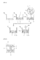
- a first layer L1 is formed by filling a mixture including long fibers and phenol resin into a mold 100.
- the mold 100 is a shape as a hollow cylindrical body, one end of which is blocked.
- a core C provided a plurality of through holes 2 is inserted in the mold 100 to be positioned on the first layer L1.
- the core C which is a disk having a uniform thickness, has the through holes 2 which are through upper surface and lower surface of the disk.
- Each of the through holes 2 has a uniformed width and length, and the through holes 2 are positioned in radial direction.
- the mixture including long fibers and phenol resin is filled in each of the through holes 2 of the core C.
- a second layer L2 is formed on the core C by filling the mixture including long fibers and phenol resin into the mold 100.
- the first layer L1, the core C, and the second layer L2 in the mold 100 are pressed and heated to form a pressed body, and the molded body is separated from the mold 100.
- the molded body is inserted inside a furnace and then is pyrolysed under a high temperature to form a preform.
- the temperature for pyrolyzing the molded body is within a range of 1200°C to 2000°C.
- the core C in the molded body melts and the core C is removed from the molded body.
- the part from which the core C is removed by such a melting becomes cooling channels 24 and the mixture filled in the through holes 2 of the core C becomes connection portions 23 which connect the first layer L1 and the second layer L2 in the final product.
- each of the first layer L1 and the second layer L2 becomes the disk portion.
- the preform is machined.
- a step infiltrating the preform with a molten silicon is proceeded. Since melting temperature of the silicon is within a range of 1400°C to 2000°C, under the melting temperature, the silicon melts and then is infiltrated into the preform. After processing such an infiltration step, the preform infiltrated with the silicone thus obtained is cooled.
- the silicon combines the preform, which is a carbon, to form a silicon carbide, and the silicon, which is not combined with the preform, is filled inside the preform.
- the preform which is combined with the molten silicon becomes a carbon-ceramic brake disk that a matrix is carbon carbide, that is, ceramic, and the carbon fibers have a reinforcing effect on the surrounding carbon carbide matrix.
- the carbon-ceramic brake disk manufactured as a prior method has a problem that the mixture including long fibers is not filled into each of narrow through holes 2 of the core C fully since the mixture includes long fibers and the mixture including the long fibers is filled into the through holes of the core C.
- the width of the connection portion 23 is getting narrow and the shape of the connection portion 23 is getting complex. Therefore, the mixture including long fibers is not filled more and more into the through holes of the core C fully. For this reason, as shown in FIG. 4 , the density of the connection portion 23 is low and the strength of the connection portion 23 get weak. Also, efficiency of the heat transfer of the connection portion 23 get low because of the low density of the connection portion 23, therefore, frictional heat generated in braking operation is not efficiently dissipated through the cooling channels 24.
- An object of the present invention is to improve structural strength of a connection portion connecting two disk portions and to improve an efficiency of the heat transfer of the connection portion.
- a carbon-ceramic brake disk including a first disk portion, a second disk portion positioned at a predetermined distance from the first disk portion, a plurality of connection portions connecting the first disk portion and the second disk portion, a plurality of cooling channels formed between the connection portions, wherein each of the first disk portion and the second disk portion includes long fibers, and wherein the connection portion includes short fibers.
- the long fiber may have a length of from 11mm to 50mm.
- the short fiber may have a length of between from 1mm to 10mm.
- a part of the long fiber adjacent to the connection portion may be bent toward the connection portion.
- Each of the short fiber and the long fiber may be a carbon fiber.
- an method for manufacturing a carbon-ceramic including forming a first layer in a mold by filling a mixture including long fibers into the mold, inserting a core which has a plurality of through holes into the mold so as to be positioned on the first layer, filling a mixture including short fibers into the through holes of the core, forming a second layer on the core by filling a mixture including long fibers into the mold; and pressure-heating the first layer, the core, and the second layer in the mold.
- the core may includes a first disk core provided a plurality of through holes, and a second disk core and a third disk core which are lower than the first disk core in strength and melting temperature, which are formed in the same shape as the first disk core, wherein the second disk core is attached to one side of the first disk core and the third disk core is attached to the other side of the first disk core.
- the present invention improves the strength of the connection portions which connect two disk portions and improves efficiency of the heat transfer of the connection portion. Therefore, the frictional heat generated in braking operating is efficiently dissipated outside. As a result, it is possible to prevent the thermal distortion of a hot part and a brake disk.
- the present invention provides advantages that it is easy to fill a mixture into each of the through holes of the core since the mixture including short fibers is filled into each of through holes forming the connection portion, and the mixture can be densely filled into each of the through holes.
- FIG. 5 is a perspective view of a carbon-ceramic brake disk according to the present invention.
- an embodiment of the carbon-ceramic brake disk includes a first disk portion 51, a second disk portion 52 positioned at a predetermined distance from the first disk portion 51, a plurality of connection portion 53 connecting the first disk portion 51 and the second disk portion 52, a plurality of cooling channels 54 formed between the connection portions 53, wherein each of the first and second disk portions 51 and 52 includes long fibers F1 and wherein the connection portion 53 includes short fibers F2.
- Each of the first and second disk portions 51 and 52 is a disk as a ring shape, which has a uniform thickness and a central hole H pierced at the center.
- connection portion 53 One end of the connection portion 53 is connected to one side face of the first connection portion 51, and the other end of the connection portion 53 is connected to one side face of the second connection portion 52.
- an inner surface is the surface to which the connection portion 53 is connected, and an outer surface is an opposite surface of the inner surface.
- a frictional layer may be formed at each of the first and second disk portions 51 and 52, as a uniform thickness from the outer surface into the inner portion.
- the other part except the frictional layer is a support layer.
- the support layer may be preferably made of a material to have durability, and the frictional layer may be preferably made of a material to have wear resistance and heat resistance.
- the support layer includes long fibers F1, silicon carbide, and silicon, etc.
- the frictional layer includes silicon carbide, and silicon, etc.
- Each of the support layer and the frictional layer may include short fiber F2.
- the short fiber F2 may be a carbon fiber.
- the long fiber F1 may have a length of from 11mm to 50mm.
- the long fiber F1 may be a carbon fiber. At least 60% or more of the long fibers F1 may be arranged in circumferential direction of the disk portion. As shown in FIG. 6 , a part of the long fiber adjacent to the connection portion 53 may be bent toward the connection portion.
- the first disk portion 51 and the second disk portion 52 keep a predetermined gap each other by the connection portions 53.
- the connection portions 53 may be arranged at regularly spaced interval.
- a horizontal section (which is parallel to the first disk portion and the second disk portion; shape of the connection portion 53 may have a uniform thickness (width) and a uniform length, wherein both end portion of the connection portion 53 may be formed as a curve.
- a horizontal section shape of the connection portion 53 can be formed variously.
- the connection portion 53 includes short fibers.
- the short fiber F2 may have a length of from 1mm to 10mm.
- the short fiber F2 may be a carbon fiber.
- the boundary part where is met with the connection portion 53 and the disk portion may include the short fibers F2 and the long fibers F1 as a mixed state, each other.
- the space between the two connection portions 53 which are continuous with each other becomes a cooling channel 54. That is, the cooling channel 54 is formed by each inner surface of the two connection portions 53 and each the inner surface of the first and second disk portions 51 and 52.
- the cooling channel 54 is formed in radial direction of the first and second disk portions 51 and 52. Accordingly, when the carbon-ceramic brake disk 50 rotates, air inflows into the central hole H of the first and second disk portions 51 and 52 and passes the cooling channels 24 and outflows toward the outer circumference side of the first and second disk portions 51 and 52.
- Embodiments of the method for manufacturing a carbon-ceramic brake disk according to the present invention are described as below.
- a first layer L1 is formed by filling a first mixture including long fibers F1 into a mold 100.
- the mold 100 is a shape as a hollow cylindrical body, one end of which is blocked.
- the first mixture includes long fibers F1 and phenol resin.
- the long fiber F1 may be a carbon fiber.
- Short fibers F2 may be mixed to the first mixture, additionally.
- a core C' is inserted in the mold 100 into so as to be positioned on the first layer L1.
- the core C' is a disk shape provided a plurality of through holes 3.
- the disk shape has a uniform thickness, and each of the through holes 3 is formed to penetrate the disk shape from one side to other side.
- the shape and arrangement of the through holes 3 in the core C' are the same as the horizontal section shape of the connection portions 53 of the carbon-ceramic brake disk.
- the core C' may be a plastic material.
- the second embodiment of the core C' includes a first disk core 4 having a plurality of through holes 3, and a second disk core 5 and a third disk core 6 which are formed in the same shape as the first disk core, wherein the second disk core 5 is attached to one side of the first disk core 4 and the third disk core 6 is attached to the other side of the first disk core 4.
- the first disk core 4 has a uniform thickness.
- the through holes 3 of the first disk core 4 are formed as the same as shape of the connection portions 53 of the carbon-ceramic brake disk.
- the second and third disk core 5 and 6 may be a material which is lower than the first disk core 4 in strength and melting temperature.
- the first disk core 4 may be a plastic material, the second and third disk cores 5 and 6 may be a polystyrene material.
- a second mixture including short fibers F2 is filled in each of the through holes 3 of the core C'.
- the second mixture includes the short fibers F2 and phenol resin.
- the short fiber F2 may be a carbon fiber.
- the second mixture is densely filled in the through holes 3 of the core C' since the second mixture including short fibers F2 is filled in each of the through holes 3 of the core C'.
- a second layer L2 is formed on the core C' by filling the first mixture into the mold 100.
- the first layer L1, the core C', and the second layer L2 harden by pressure-heating the first layer L1, the core C', and the second layer L2 in the mold 100. That is, a cylinder type tool presses the first layer L1, the core C', and the second layer L2 in the mold 100, and at that time a heater provided at the mold heats the first layer L1, the core C', and the second layer L2 in the mold 100.
- the first disk core 4 is not changed in shape and the second and third disk cores 5 and 6 shrink or melt.
- the second mixture which has been filled in each of the through holes of the second and third disk cores 5 and 6 is pressed and entered into each of the through holes 3 of the first disk core 4 since the second and third disk cores 5 and 6 shrink or melt. Therefore, Density of the second mixture filled in each of the through holes 3 of the first disk core 4 becomes high.
- the molded body to harden in the mold 100 is separated from the mold 100.
- the molded body is inserted inside a furnace and then is pyrolysed under a high temperature to form a preform.
- the temperature for pyrolysing the molded body is within a range of 1200°C and 2000°C.
- the core C' in the molded body melts and the core C' is removed from the molded body. Therefore, in the molded body, the part from which the core C is removed by such a melting becomes cooling channels 54, and the second mixture, in final product, filled in the through holes 3 of the core C' becomes connection portions 53 which connect the first and second layers L1 and L2. Also, in final product, each of the first and second layers L1 and L2 becomes the first disk portion 51 and the second disk portion 52.
- the preform is machined.
- a step infiltrating the preform with a molten silicon is proceeded. Since melting temperature of the silicon is within a range of 1400°C and 2000°C, under the melting temperature, the molten silicon melts and then is infiltrated into the preform. After processing such an infiltration step, the preform infiltrated with the silicone thus obtained is cooled.
- the silicon combines with the preform, which is a carbon, to form a silicon carbide (SiC), and the silicon (Si), which is not combined with the preform, is filled inside the preform.
- the preform which is combined with the molten silicon becomes a carbon-ceramic brake disk that a matrix is carbon carbide, that is, ceramic, and the carbon fibers have a reinforcing effect on the surrounding carbon carbide matrix.
- a carbon-ceramic brake disk according to the present invention consists of a brake system, and brake pads of the brake system are pressed on the outer surface of the first disk portion 51 and the outer surface of the second disk portion 52, therefore, a vehicle having the brake system is decelerated and the vehicle is stopped.
- a carbon-ceramic brake disk according to the present invention provides an advantage that the density of the connection portion 53 is high because the connection portion 53 connecting the first disk portion 51 and the second disk portion 52 includes the short fibers F2. Especially, even if the width (thickness) of the connection portion 53 is narrow and the shape of the connection portion is complex, the density of connection portion 53 is high because of including the sort fibers. As a result, the strength of the connection portion is great, and for improving efficiency of dissipating heat, it is possible to make the width of the connection portion narrow and it is possible to make the structure of the connection portion complex and various. Efficiency of heat transfer is excellent because the density of the connection portion 53 is high. Therefore, frictional heat generated in braking operation is efficiently dissipated through the cooling channels 24. In addition, it is possible to prevent the connection portion from oxidizing by external air or foreign substance because the density of the connection portion 53 is high. Therefore, the strength of the connection portion 53 is kept.
- a carbon-ceramic brake disk according to the present invention prevents the connection portion from destroying by external impact or highspeed running since the strength of the connection portion is great. Also, the present invention prevents the thermal distortion of hot part and brake disk since the frictional heat generated in braking operating is efficiently radiated outside.
- a method for manufacturing a carbon-ceramic brake disk according to the present invention provides advantages that it is easy to fill a mixture into each of the through holes of the core since the mixture including short fibers is filled into each of through holes forming the connection portion, and the mixture can be densely filled into each of the through holes of the core.
Landscapes
- Chemical & Material Sciences (AREA)
- Engineering & Computer Science (AREA)
- Ceramic Engineering (AREA)
- Materials Engineering (AREA)
- Organic Chemistry (AREA)
- Structural Engineering (AREA)
- Manufacturing & Machinery (AREA)
- Chemical Kinetics & Catalysis (AREA)
- Mechanical Engineering (AREA)
- General Engineering & Computer Science (AREA)
- Metallurgy (AREA)
- Composite Materials (AREA)
- Braking Arrangements (AREA)
- Ceramic Products (AREA)
Applications Claiming Priority (2)
| Application Number | Priority Date | Filing Date | Title |
|---|---|---|---|
| KR1020100119592A KR101247582B1 (ko) | 2010-11-29 | 2010-11-29 | 탄소-세라믹 브레이크 디스크 및 그 제작방법 |
| PCT/KR2011/009126 WO2012074258A2 (ko) | 2010-11-29 | 2011-11-28 | 탄소-세라믹 브레이크 디스크 및 그 제작방법 |
Publications (3)
| Publication Number | Publication Date |
|---|---|
| EP2647862A2 true EP2647862A2 (de) | 2013-10-09 |
| EP2647862A4 EP2647862A4 (de) | 2015-05-06 |
| EP2647862B1 EP2647862B1 (de) | 2018-01-03 |
Family
ID=46172377
Family Applications (1)
| Application Number | Title | Priority Date | Filing Date |
|---|---|---|---|
| EP11844022.1A Active EP2647862B1 (de) | 2010-11-29 | 2011-11-28 | Herstellungsverfahren für eine kohlenstoff-keramik-bremsscheibe |
Country Status (3)
| Country | Link |
|---|---|
| EP (1) | EP2647862B1 (de) |
| KR (1) | KR101247582B1 (de) |
| WO (1) | WO2012074258A2 (de) |
Cited By (2)
| Publication number | Priority date | Publication date | Assignee | Title |
|---|---|---|---|---|
| AU2016200274B2 (en) * | 2015-05-12 | 2017-09-21 | Dacc Carbon Co., Ltd. | Carbon ceramic brake disc and method for manufacturing the same |
| US11702370B2 (en) | 2018-01-10 | 2023-07-18 | SiC Technologies, Inc. | Systems, devices, and methods for manufacturing carbon ceramic brake discs |
Families Citing this family (2)
| Publication number | Priority date | Publication date | Assignee | Title |
|---|---|---|---|---|
| KR20220043585A (ko) | 2020-09-29 | 2022-04-05 | 주식회사 뱅크정밀항공 | 브레이크 디스크의 마찰층 제작을 위한 절단 장치 및 그 절단방법 |
| CN119707496A (zh) * | 2023-09-28 | 2025-03-28 | 比亚迪股份有限公司 | 一种陶瓷刹车盘及其制备方法和用途 |
Family Cites Families (10)
| Publication number | Priority date | Publication date | Assignee | Title |
|---|---|---|---|---|
| DE4438455C1 (de) * | 1994-10-28 | 1996-05-02 | Deutsche Forsch Luft Raumfahrt | Verfahren zur Herstellung einer Reibeinheit mittels Infiltration eines porösen Kohlenstoffkörpers mit flüssigem Silizium |
| EP0777061B1 (de) * | 1995-11-24 | 2003-11-26 | Deutsches Zentrum für Luft- und Raumfahrt e.V | Bremsscheibe |
| DE19834542C5 (de) * | 1998-07-31 | 2004-07-01 | Daimlerchrysler Ag | Verfahren zur Herstellung von Verstärkungsfasern enthaltenden Körpern, danach erhältliche Körper, Verfahren zum Fügen der so erhaltenen Körper, gefügte Körper und Anwendung des Fügeverfahrens |
| DE19901215B4 (de) * | 1999-01-14 | 2004-02-19 | Menzolit-Fibron Gmbh | Scheibenbremse, Preßwerkzeug und Verfahren zur Herstellung einer Bremsscheibe |
| SK3722003A3 (en) * | 2000-09-29 | 2003-09-11 | Menzolit Fibron Gmbh | Method for producing ceramic brake disks from BMC |
| ATE371820T1 (de) * | 2000-10-18 | 2007-09-15 | Menzolit Fibron Gmbh | Verfahren zur herstellung von keramikbremsscheiben mit einem einleger im grünling vor der pyrolyse |
| KR100447840B1 (ko) * | 2002-05-20 | 2004-09-08 | 주식회사 데크 | 탄소 복합재 제조 방법 |
| DE60336270D1 (de) * | 2003-05-06 | 2011-04-14 | Freni Brembo Spa | Kernaufbau einer bremsscheibe |
| KR100588342B1 (ko) * | 2003-11-26 | 2006-06-12 | 주식회사 데크 | 동력전달용 클러치 |
| KR101051408B1 (ko) * | 2008-09-30 | 2011-07-22 | 주식회사 데크 | 내부 냉각채널을 갖는 세라믹 브레이크 디스크 로터의 제조방법 |
-
2010
- 2010-11-29 KR KR1020100119592A patent/KR101247582B1/ko active Active
-
2011
- 2011-11-28 EP EP11844022.1A patent/EP2647862B1/de active Active
- 2011-11-28 WO PCT/KR2011/009126 patent/WO2012074258A2/ko not_active Ceased
Cited By (2)
| Publication number | Priority date | Publication date | Assignee | Title |
|---|---|---|---|---|
| AU2016200274B2 (en) * | 2015-05-12 | 2017-09-21 | Dacc Carbon Co., Ltd. | Carbon ceramic brake disc and method for manufacturing the same |
| US11702370B2 (en) | 2018-01-10 | 2023-07-18 | SiC Technologies, Inc. | Systems, devices, and methods for manufacturing carbon ceramic brake discs |
Also Published As
| Publication number | Publication date |
|---|---|
| KR20120058004A (ko) | 2012-06-07 |
| WO2012074258A3 (ko) | 2012-10-18 |
| WO2012074258A2 (ko) | 2012-06-07 |
| EP2647862A4 (de) | 2015-05-06 |
| KR101247582B1 (ko) | 2013-04-02 |
| EP2647862B1 (de) | 2018-01-03 |
Similar Documents
| Publication | Publication Date | Title |
|---|---|---|
| JP3911522B2 (ja) | 摩擦ディスクとその製造方法 | |
| KR101304309B1 (ko) | 탄소-세라믹 브레이크 디스크 | |
| JP2002502480A (ja) | 摩擦ユニット | |
| EP2647862A2 (de) | Kohlenstoff-keramik-bremsscheibe und herstellungsverfahren dafür | |
| KR101745627B1 (ko) | 탄소 세라믹 브레이크 디스크 및 이를 제조하는 방법 | |
| KR101051408B1 (ko) | 내부 냉각채널을 갖는 세라믹 브레이크 디스크 로터의 제조방법 | |
| JP2014505841A (ja) | カーボンセラミック摩擦ディスクおよびその製造方法 | |
| KR101304188B1 (ko) | 탄소-세라믹 브레이크 디스크 및 이를 만드는 방법 | |
| CN108644260B (zh) | 一种高速列车用轻量一体化制动轴盘的制备方法 | |
| KR101242079B1 (ko) | 탄소-세라믹 브레이크 디스크 및 이를 만드는 방법 | |
| US20110100773A1 (en) | Disc brake | |
| KR101610131B1 (ko) | 자동차 브레이크 디스크 제조 방법 | |
| KR101258828B1 (ko) | 탄소-세라믹 브레이크 디스크 및 그 제작방법 및 그 제작방법에 사용되는 다기능 코어 | |
| CN208719193U (zh) | 一种带径向和周向导气槽的制动盘 | |
| KR101242078B1 (ko) | 일체형 탄소-세라믹 브레이크 디스크 및 그 제작방법 | |
| KR20120058001A (ko) | 일체형 탄소-세라믹 브레이크 디스크 및 그 제작방법 | |
| KR101304303B1 (ko) | 탄소-세라믹 브레이크 디스크 및 이를 만드는 방법 | |
| CN208719191U (zh) | 一种高速列车用带导气槽制动轴盘 | |
| KR101216144B1 (ko) | 탄소-세라믹 브레이크 디스크 및 이를 제조하는 방법 | |
| KR101370558B1 (ko) | 탄소-세라믹 브레이크 디스크 및 이를 만드는 방법 | |
| KR20120057866A (ko) | 탄소-세라믹 브레이크 디스크 및 이를 만드는 방법 | |
| US12092179B2 (en) | Internally ventilated rotor | |
| KR20110095543A (ko) | 탄소-세라믹 브레이크 디스크 및 이를 제조하는 방법 | |
| CN208719192U (zh) | 一种高速列车用轻量一体化制动轴盘 | |
| KR101336101B1 (ko) | 탄소-세라믹 브레이크 디스크 및 이를 만드는 방법 |
Legal Events
| Date | Code | Title | Description |
|---|---|---|---|
| PUAI | Public reference made under article 153(3) epc to a published international application that has entered the european phase |
Free format text: ORIGINAL CODE: 0009012 |
|
| 17P | Request for examination filed |
Effective date: 20130611 |
|
| AK | Designated contracting states |
Kind code of ref document: A2 Designated state(s): AL AT BE BG CH CY CZ DE DK EE ES FI FR GB GR HR HU IE IS IT LI LT LU LV MC MK MT NL NO PL PT RO RS SE SI SK SM TR |
|
| DAX | Request for extension of the european patent (deleted) | ||
| A4 | Supplementary search report drawn up and despatched |
Effective date: 20150407 |
|
| RIC1 | Information provided on ipc code assigned before grant |
Ipc: F16D 65/00 20060101ALI20150330BHEP Ipc: F16D 65/12 20060101AFI20150330BHEP Ipc: C22C 49/00 20060101ALI20150330BHEP Ipc: C04B 35/573 20060101ALI20150330BHEP |
|
| RAP1 | Party data changed (applicant data changed or rights of an application transferred) |
Owner name: DACC CARBON |
|
| 17Q | First examination report despatched |
Effective date: 20161215 |
|
| GRAP | Despatch of communication of intention to grant a patent |
Free format text: ORIGINAL CODE: EPIDOSNIGR1 |
|
| INTG | Intention to grant announced |
Effective date: 20170616 |
|
| GRAS | Grant fee paid |
Free format text: ORIGINAL CODE: EPIDOSNIGR3 |
|
| GRAA | (expected) grant |
Free format text: ORIGINAL CODE: 0009210 |
|
| AK | Designated contracting states |
Kind code of ref document: B1 Designated state(s): AL AT BE BG CH CY CZ DE DK EE ES FI FR GB GR HR HU IE IS IT LI LT LU LV MC MK MT NL NO PL PT RO RS SE SI SK SM TR |
|
| REG | Reference to a national code |
Ref country code: GB Ref legal event code: FG4D |
|
| REG | Reference to a national code |
Ref country code: CH Ref legal event code: EP Ref country code: AT Ref legal event code: REF Ref document number: 960576 Country of ref document: AT Kind code of ref document: T Effective date: 20180115 |
|
| REG | Reference to a national code |
Ref country code: IE Ref legal event code: FG4D |
|
| REG | Reference to a national code |
Ref country code: DE Ref legal event code: R096 Ref document number: 602011044816 Country of ref document: DE |
|
| REG | Reference to a national code |
Ref country code: NL Ref legal event code: MP Effective date: 20180103 |
|
| REG | Reference to a national code |
Ref country code: LT Ref legal event code: MG4D |
|
| REG | Reference to a national code |
Ref country code: AT Ref legal event code: MK05 Ref document number: 960576 Country of ref document: AT Kind code of ref document: T Effective date: 20180103 |
|
| PG25 | Lapsed in a contracting state [announced via postgrant information from national office to epo] |
Ref country code: NL Free format text: LAPSE BECAUSE OF FAILURE TO SUBMIT A TRANSLATION OF THE DESCRIPTION OR TO PAY THE FEE WITHIN THE PRESCRIBED TIME-LIMIT Effective date: 20180103 |
|
| PG25 | Lapsed in a contracting state [announced via postgrant information from national office to epo] |
Ref country code: LT Free format text: LAPSE BECAUSE OF FAILURE TO SUBMIT A TRANSLATION OF THE DESCRIPTION OR TO PAY THE FEE WITHIN THE PRESCRIBED TIME-LIMIT Effective date: 20180103 Ref country code: CY Free format text: LAPSE BECAUSE OF FAILURE TO SUBMIT A TRANSLATION OF THE DESCRIPTION OR TO PAY THE FEE WITHIN THE PRESCRIBED TIME-LIMIT Effective date: 20180103 Ref country code: FI Free format text: LAPSE BECAUSE OF FAILURE TO SUBMIT A TRANSLATION OF THE DESCRIPTION OR TO PAY THE FEE WITHIN THE PRESCRIBED TIME-LIMIT Effective date: 20180103 Ref country code: NO Free format text: LAPSE BECAUSE OF FAILURE TO SUBMIT A TRANSLATION OF THE DESCRIPTION OR TO PAY THE FEE WITHIN THE PRESCRIBED TIME-LIMIT Effective date: 20180403 Ref country code: HR Free format text: LAPSE BECAUSE OF FAILURE TO SUBMIT A TRANSLATION OF THE DESCRIPTION OR TO PAY THE FEE WITHIN THE PRESCRIBED TIME-LIMIT Effective date: 20180103 Ref country code: ES Free format text: LAPSE BECAUSE OF FAILURE TO SUBMIT A TRANSLATION OF THE DESCRIPTION OR TO PAY THE FEE WITHIN THE PRESCRIBED TIME-LIMIT Effective date: 20180103 |
|
| PG25 | Lapsed in a contracting state [announced via postgrant information from national office to epo] |
Ref country code: RS Free format text: LAPSE BECAUSE OF FAILURE TO SUBMIT A TRANSLATION OF THE DESCRIPTION OR TO PAY THE FEE WITHIN THE PRESCRIBED TIME-LIMIT Effective date: 20180103 Ref country code: SE Free format text: LAPSE BECAUSE OF FAILURE TO SUBMIT A TRANSLATION OF THE DESCRIPTION OR TO PAY THE FEE WITHIN THE PRESCRIBED TIME-LIMIT Effective date: 20180103 Ref country code: LV Free format text: LAPSE BECAUSE OF FAILURE TO SUBMIT A TRANSLATION OF THE DESCRIPTION OR TO PAY THE FEE WITHIN THE PRESCRIBED TIME-LIMIT Effective date: 20180103 Ref country code: GR Free format text: LAPSE BECAUSE OF FAILURE TO SUBMIT A TRANSLATION OF THE DESCRIPTION OR TO PAY THE FEE WITHIN THE PRESCRIBED TIME-LIMIT Effective date: 20180404 Ref country code: PL Free format text: LAPSE BECAUSE OF FAILURE TO SUBMIT A TRANSLATION OF THE DESCRIPTION OR TO PAY THE FEE WITHIN THE PRESCRIBED TIME-LIMIT Effective date: 20180103 Ref country code: IS Free format text: LAPSE BECAUSE OF FAILURE TO SUBMIT A TRANSLATION OF THE DESCRIPTION OR TO PAY THE FEE WITHIN THE PRESCRIBED TIME-LIMIT Effective date: 20180503 Ref country code: BG Free format text: LAPSE BECAUSE OF FAILURE TO SUBMIT A TRANSLATION OF THE DESCRIPTION OR TO PAY THE FEE WITHIN THE PRESCRIBED TIME-LIMIT Effective date: 20180403 Ref country code: AT Free format text: LAPSE BECAUSE OF FAILURE TO SUBMIT A TRANSLATION OF THE DESCRIPTION OR TO PAY THE FEE WITHIN THE PRESCRIBED TIME-LIMIT Effective date: 20180103 |
|
| REG | Reference to a national code |
Ref country code: DE Ref legal event code: R097 Ref document number: 602011044816 Country of ref document: DE |
|
| PG25 | Lapsed in a contracting state [announced via postgrant information from national office to epo] |
Ref country code: AL Free format text: LAPSE BECAUSE OF FAILURE TO SUBMIT A TRANSLATION OF THE DESCRIPTION OR TO PAY THE FEE WITHIN THE PRESCRIBED TIME-LIMIT Effective date: 20180103 Ref country code: EE Free format text: LAPSE BECAUSE OF FAILURE TO SUBMIT A TRANSLATION OF THE DESCRIPTION OR TO PAY THE FEE WITHIN THE PRESCRIBED TIME-LIMIT Effective date: 20180103 Ref country code: RO Free format text: LAPSE BECAUSE OF FAILURE TO SUBMIT A TRANSLATION OF THE DESCRIPTION OR TO PAY THE FEE WITHIN THE PRESCRIBED TIME-LIMIT Effective date: 20180103 |
|
| PLBE | No opposition filed within time limit |
Free format text: ORIGINAL CODE: 0009261 |
|
| STAA | Information on the status of an ep patent application or granted ep patent |
Free format text: STATUS: NO OPPOSITION FILED WITHIN TIME LIMIT |
|
| PG25 | Lapsed in a contracting state [announced via postgrant information from national office to epo] |
Ref country code: SK Free format text: LAPSE BECAUSE OF FAILURE TO SUBMIT A TRANSLATION OF THE DESCRIPTION OR TO PAY THE FEE WITHIN THE PRESCRIBED TIME-LIMIT Effective date: 20180103 Ref country code: CZ Free format text: LAPSE BECAUSE OF FAILURE TO SUBMIT A TRANSLATION OF THE DESCRIPTION OR TO PAY THE FEE WITHIN THE PRESCRIBED TIME-LIMIT Effective date: 20180103 Ref country code: DK Free format text: LAPSE BECAUSE OF FAILURE TO SUBMIT A TRANSLATION OF THE DESCRIPTION OR TO PAY THE FEE WITHIN THE PRESCRIBED TIME-LIMIT Effective date: 20180103 Ref country code: SM Free format text: LAPSE BECAUSE OF FAILURE TO SUBMIT A TRANSLATION OF THE DESCRIPTION OR TO PAY THE FEE WITHIN THE PRESCRIBED TIME-LIMIT Effective date: 20180103 |
|
| 26N | No opposition filed |
Effective date: 20181005 |
|
| PG25 | Lapsed in a contracting state [announced via postgrant information from national office to epo] |
Ref country code: SI Free format text: LAPSE BECAUSE OF FAILURE TO SUBMIT A TRANSLATION OF THE DESCRIPTION OR TO PAY THE FEE WITHIN THE PRESCRIBED TIME-LIMIT Effective date: 20180103 |
|
| REG | Reference to a national code |
Ref country code: CH Ref legal event code: PL |
|
| GBPC | Gb: european patent ceased through non-payment of renewal fee |
Effective date: 20181128 |
|
| PG25 | Lapsed in a contracting state [announced via postgrant information from national office to epo] |
Ref country code: LU Free format text: LAPSE BECAUSE OF NON-PAYMENT OF DUE FEES Effective date: 20181128 Ref country code: MC Free format text: LAPSE BECAUSE OF FAILURE TO SUBMIT A TRANSLATION OF THE DESCRIPTION OR TO PAY THE FEE WITHIN THE PRESCRIBED TIME-LIMIT Effective date: 20180103 |
|
| REG | Reference to a national code |
Ref country code: BE Ref legal event code: MM Effective date: 20181130 |
|
| REG | Reference to a national code |
Ref country code: IE Ref legal event code: MM4A |
|
| PG25 | Lapsed in a contracting state [announced via postgrant information from national office to epo] |
Ref country code: LI Free format text: LAPSE BECAUSE OF NON-PAYMENT OF DUE FEES Effective date: 20181130 Ref country code: CH Free format text: LAPSE BECAUSE OF NON-PAYMENT OF DUE FEES Effective date: 20181130 |
|
| PG25 | Lapsed in a contracting state [announced via postgrant information from national office to epo] |
Ref country code: IE Free format text: LAPSE BECAUSE OF NON-PAYMENT OF DUE FEES Effective date: 20181128 |
|
| PG25 | Lapsed in a contracting state [announced via postgrant information from national office to epo] |
Ref country code: BE Free format text: LAPSE BECAUSE OF NON-PAYMENT OF DUE FEES Effective date: 20181130 |
|
| PG25 | Lapsed in a contracting state [announced via postgrant information from national office to epo] |
Ref country code: GB Free format text: LAPSE BECAUSE OF NON-PAYMENT OF DUE FEES Effective date: 20181128 |
|
| PG25 | Lapsed in a contracting state [announced via postgrant information from national office to epo] |
Ref country code: MT Free format text: LAPSE BECAUSE OF NON-PAYMENT OF DUE FEES Effective date: 20181128 |
|
| PG25 | Lapsed in a contracting state [announced via postgrant information from national office to epo] |
Ref country code: TR Free format text: LAPSE BECAUSE OF FAILURE TO SUBMIT A TRANSLATION OF THE DESCRIPTION OR TO PAY THE FEE WITHIN THE PRESCRIBED TIME-LIMIT Effective date: 20180103 |
|
| PG25 | Lapsed in a contracting state [announced via postgrant information from national office to epo] |
Ref country code: PT Free format text: LAPSE BECAUSE OF FAILURE TO SUBMIT A TRANSLATION OF THE DESCRIPTION OR TO PAY THE FEE WITHIN THE PRESCRIBED TIME-LIMIT Effective date: 20180103 |
|
| PG25 | Lapsed in a contracting state [announced via postgrant information from national office to epo] |
Ref country code: MK Free format text: LAPSE BECAUSE OF NON-PAYMENT OF DUE FEES Effective date: 20180103 Ref country code: HU Free format text: LAPSE BECAUSE OF FAILURE TO SUBMIT A TRANSLATION OF THE DESCRIPTION OR TO PAY THE FEE WITHIN THE PRESCRIBED TIME-LIMIT; INVALID AB INITIO Effective date: 20111128 |
|
| PGFP | Annual fee paid to national office [announced via postgrant information from national office to epo] |
Ref country code: IT Payment date: 20250924 Year of fee payment: 15 |
|
| PGFP | Annual fee paid to national office [announced via postgrant information from national office to epo] |
Ref country code: FR Payment date: 20250925 Year of fee payment: 15 |
|
| PGFP | Annual fee paid to national office [announced via postgrant information from national office to epo] |
Ref country code: DE Payment date: 20250922 Year of fee payment: 15 |