EP2647883A2 - Dispositif de commande hydraulique - Google Patents
Dispositif de commande hydraulique Download PDFInfo
- Publication number
- EP2647883A2 EP2647883A2 EP13160813.5A EP13160813A EP2647883A2 EP 2647883 A2 EP2647883 A2 EP 2647883A2 EP 13160813 A EP13160813 A EP 13160813A EP 2647883 A2 EP2647883 A2 EP 2647883A2
- Authority
- EP
- European Patent Office
- Prior art keywords
- pressure
- valve
- control device
- hydraulic control
- reduction valve
- Prior art date
- Legal status (The legal status is an assumption and is not a legal conclusion. Google has not performed a legal analysis and makes no representation as to the accuracy of the status listed.)
- Granted
Links
Images


Classifications
-
- F—MECHANICAL ENGINEERING; LIGHTING; HEATING; WEAPONS; BLASTING
- F15—FLUID-PRESSURE ACTUATORS; HYDRAULICS OR PNEUMATICS IN GENERAL
- F15B—SYSTEMS ACTING BY MEANS OF FLUIDS IN GENERAL; FLUID-PRESSURE ACTUATORS, e.g. SERVOMOTORS; DETAILS OF FLUID-PRESSURE SYSTEMS, NOT OTHERWISE PROVIDED FOR
- F15B1/00—Installations or systems with accumulators; Supply reservoir or sump assemblies
- F15B1/02—Installations or systems with accumulators
- F15B1/027—Installations or systems with accumulators having accumulator charging devices
-
- F—MECHANICAL ENGINEERING; LIGHTING; HEATING; WEAPONS; BLASTING
- F16—ENGINEERING ELEMENTS AND UNITS; GENERAL MEASURES FOR PRODUCING AND MAINTAINING EFFECTIVE FUNCTIONING OF MACHINES OR INSTALLATIONS; THERMAL INSULATION IN GENERAL
- F16D—COUPLINGS FOR TRANSMITTING ROTATION; CLUTCHES; BRAKES
- F16D48/00—External control of clutches
- F16D48/02—Control by fluid pressure
- F16D48/0206—Control by fluid pressure in a system with a plurality of fluid-actuated clutches
-
- F—MECHANICAL ENGINEERING; LIGHTING; HEATING; WEAPONS; BLASTING
- F16—ENGINEERING ELEMENTS AND UNITS; GENERAL MEASURES FOR PRODUCING AND MAINTAINING EFFECTIVE FUNCTIONING OF MACHINES OR INSTALLATIONS; THERMAL INSULATION IN GENERAL
- F16H—GEARING
- F16H61/00—Control functions within control units of change-speed- or reversing-gearings for conveying rotary motion ; Control of exclusively fluid gearing, friction gearing, gearings with endless flexible members or other particular types of gearing
- F16H61/26—Generation or transmission of movements for final actuating mechanisms
- F16H61/28—Generation or transmission of movements for final actuating mechanisms with at least one movement of the final actuating mechanism being caused by a non-mechanical force, e.g. power-assisted
- F16H61/30—Hydraulic or pneumatic motors or related fluid control means therefor
-
- F—MECHANICAL ENGINEERING; LIGHTING; HEATING; WEAPONS; BLASTING
- F16—ENGINEERING ELEMENTS AND UNITS; GENERAL MEASURES FOR PRODUCING AND MAINTAINING EFFECTIVE FUNCTIONING OF MACHINES OR INSTALLATIONS; THERMAL INSULATION IN GENERAL
- F16H—GEARING
- F16H61/00—Control functions within control units of change-speed- or reversing-gearings for conveying rotary motion ; Control of exclusively fluid gearing, friction gearing, gearings with endless flexible members or other particular types of gearing
- F16H61/68—Control functions within control units of change-speed- or reversing-gearings for conveying rotary motion ; Control of exclusively fluid gearing, friction gearing, gearings with endless flexible members or other particular types of gearing specially adapted for stepped gearings
- F16H61/684—Control functions within control units of change-speed- or reversing-gearings for conveying rotary motion ; Control of exclusively fluid gearing, friction gearing, gearings with endless flexible members or other particular types of gearing specially adapted for stepped gearings without interruption of drive
- F16H61/688—Control functions within control units of change-speed- or reversing-gearings for conveying rotary motion ; Control of exclusively fluid gearing, friction gearing, gearings with endless flexible members or other particular types of gearing specially adapted for stepped gearings without interruption of drive with two inputs, e.g. selection of one of two torque-flow paths by clutches
-
- F—MECHANICAL ENGINEERING; LIGHTING; HEATING; WEAPONS; BLASTING
- F15—FLUID-PRESSURE ACTUATORS; HYDRAULICS OR PNEUMATICS IN GENERAL
- F15B—SYSTEMS ACTING BY MEANS OF FLUIDS IN GENERAL; FLUID-PRESSURE ACTUATORS, e.g. SERVOMOTORS; DETAILS OF FLUID-PRESSURE SYSTEMS, NOT OTHERWISE PROVIDED FOR
- F15B21/00—Common features of fluid actuator systems; Fluid-pressure actuator systems or details thereof, not covered by any other group of this subclass
- F15B21/005—Filling or draining of fluid systems
-
- F—MECHANICAL ENGINEERING; LIGHTING; HEATING; WEAPONS; BLASTING
- F15—FLUID-PRESSURE ACTUATORS; HYDRAULICS OR PNEUMATICS IN GENERAL
- F15B—SYSTEMS ACTING BY MEANS OF FLUIDS IN GENERAL; FLUID-PRESSURE ACTUATORS, e.g. SERVOMOTORS; DETAILS OF FLUID-PRESSURE SYSTEMS, NOT OTHERWISE PROVIDED FOR
- F15B2211/00—Circuits for servomotor systems
- F15B2211/20—Fluid pressure source, e.g. accumulator or variable axial piston pump
- F15B2211/205—Systems with pumps
- F15B2211/20507—Type of prime mover
- F15B2211/20515—Electric motor
-
- F—MECHANICAL ENGINEERING; LIGHTING; HEATING; WEAPONS; BLASTING
- F15—FLUID-PRESSURE ACTUATORS; HYDRAULICS OR PNEUMATICS IN GENERAL
- F15B—SYSTEMS ACTING BY MEANS OF FLUIDS IN GENERAL; FLUID-PRESSURE ACTUATORS, e.g. SERVOMOTORS; DETAILS OF FLUID-PRESSURE SYSTEMS, NOT OTHERWISE PROVIDED FOR
- F15B2211/00—Circuits for servomotor systems
- F15B2211/20—Fluid pressure source, e.g. accumulator or variable axial piston pump
- F15B2211/205—Systems with pumps
- F15B2211/2053—Type of pump
- F15B2211/20538—Type of pump constant capacity
-
- F—MECHANICAL ENGINEERING; LIGHTING; HEATING; WEAPONS; BLASTING
- F15—FLUID-PRESSURE ACTUATORS; HYDRAULICS OR PNEUMATICS IN GENERAL
- F15B—SYSTEMS ACTING BY MEANS OF FLUIDS IN GENERAL; FLUID-PRESSURE ACTUATORS, e.g. SERVOMOTORS; DETAILS OF FLUID-PRESSURE SYSTEMS, NOT OTHERWISE PROVIDED FOR
- F15B2211/00—Circuits for servomotor systems
- F15B2211/20—Fluid pressure source, e.g. accumulator or variable axial piston pump
- F15B2211/21—Systems with pressure sources other than pumps, e.g. with a pyrotechnical charge
- F15B2211/212—Systems with pressure sources other than pumps, e.g. with a pyrotechnical charge the pressure sources being accumulators
-
- F—MECHANICAL ENGINEERING; LIGHTING; HEATING; WEAPONS; BLASTING
- F15—FLUID-PRESSURE ACTUATORS; HYDRAULICS OR PNEUMATICS IN GENERAL
- F15B—SYSTEMS ACTING BY MEANS OF FLUIDS IN GENERAL; FLUID-PRESSURE ACTUATORS, e.g. SERVOMOTORS; DETAILS OF FLUID-PRESSURE SYSTEMS, NOT OTHERWISE PROVIDED FOR
- F15B2211/00—Circuits for servomotor systems
- F15B2211/50—Pressure control
- F15B2211/505—Pressure control characterised by the type of pressure control means
- F15B2211/50509—Pressure control characterised by the type of pressure control means the pressure control means controlling a pressure upstream of the pressure control means
- F15B2211/50536—Pressure control characterised by the type of pressure control means the pressure control means controlling a pressure upstream of the pressure control means using unloading valves controlling the supply pressure by diverting fluid to the return line
-
- F—MECHANICAL ENGINEERING; LIGHTING; HEATING; WEAPONS; BLASTING
- F15—FLUID-PRESSURE ACTUATORS; HYDRAULICS OR PNEUMATICS IN GENERAL
- F15B—SYSTEMS ACTING BY MEANS OF FLUIDS IN GENERAL; FLUID-PRESSURE ACTUATORS, e.g. SERVOMOTORS; DETAILS OF FLUID-PRESSURE SYSTEMS, NOT OTHERWISE PROVIDED FOR
- F15B2211/00—Circuits for servomotor systems
- F15B2211/60—Circuit components or control therefor
- F15B2211/63—Electronic controllers
- F15B2211/6303—Electronic controllers using input signals
- F15B2211/6306—Electronic controllers using input signals representing a pressure
- F15B2211/6309—Electronic controllers using input signals representing a pressure the pressure being a pressure source supply pressure
-
- F—MECHANICAL ENGINEERING; LIGHTING; HEATING; WEAPONS; BLASTING
- F15—FLUID-PRESSURE ACTUATORS; HYDRAULICS OR PNEUMATICS IN GENERAL
- F15B—SYSTEMS ACTING BY MEANS OF FLUIDS IN GENERAL; FLUID-PRESSURE ACTUATORS, e.g. SERVOMOTORS; DETAILS OF FLUID-PRESSURE SYSTEMS, NOT OTHERWISE PROVIDED FOR
- F15B2211/00—Circuits for servomotor systems
- F15B2211/60—Circuit components or control therefor
- F15B2211/63—Electronic controllers
- F15B2211/6303—Electronic controllers using input signals
- F15B2211/6306—Electronic controllers using input signals representing a pressure
- F15B2211/6313—Electronic controllers using input signals representing a pressure the pressure being a load pressure
-
- F—MECHANICAL ENGINEERING; LIGHTING; HEATING; WEAPONS; BLASTING
- F15—FLUID-PRESSURE ACTUATORS; HYDRAULICS OR PNEUMATICS IN GENERAL
- F15B—SYSTEMS ACTING BY MEANS OF FLUIDS IN GENERAL; FLUID-PRESSURE ACTUATORS, e.g. SERVOMOTORS; DETAILS OF FLUID-PRESSURE SYSTEMS, NOT OTHERWISE PROVIDED FOR
- F15B2211/00—Circuits for servomotor systems
- F15B2211/70—Output members, e.g. hydraulic motors or cylinders or control therefor
- F15B2211/71—Multiple output members, e.g. multiple hydraulic motors or cylinders
- F15B2211/7142—Multiple output members, e.g. multiple hydraulic motors or cylinders the output members being arranged in multiple groups
-
- F—MECHANICAL ENGINEERING; LIGHTING; HEATING; WEAPONS; BLASTING
- F16—ENGINEERING ELEMENTS AND UNITS; GENERAL MEASURES FOR PRODUCING AND MAINTAINING EFFECTIVE FUNCTIONING OF MACHINES OR INSTALLATIONS; THERMAL INSULATION IN GENERAL
- F16D—COUPLINGS FOR TRANSMITTING ROTATION; CLUTCHES; BRAKES
- F16D48/00—External control of clutches
- F16D48/02—Control by fluid pressure
- F16D2048/0203—Control by fluid pressure with an accumulator; Details thereof
-
- F—MECHANICAL ENGINEERING; LIGHTING; HEATING; WEAPONS; BLASTING
- F16—ENGINEERING ELEMENTS AND UNITS; GENERAL MEASURES FOR PRODUCING AND MAINTAINING EFFECTIVE FUNCTIONING OF MACHINES OR INSTALLATIONS; THERMAL INSULATION IN GENERAL
- F16D—COUPLINGS FOR TRANSMITTING ROTATION; CLUTCHES; BRAKES
- F16D48/00—External control of clutches
- F16D48/02—Control by fluid pressure
- F16D2048/0209—Control by fluid pressure characterised by fluid valves having control pistons, e.g. spools
-
- F—MECHANICAL ENGINEERING; LIGHTING; HEATING; WEAPONS; BLASTING
- F16—ENGINEERING ELEMENTS AND UNITS; GENERAL MEASURES FOR PRODUCING AND MAINTAINING EFFECTIVE FUNCTIONING OF MACHINES OR INSTALLATIONS; THERMAL INSULATION IN GENERAL
- F16D—COUPLINGS FOR TRANSMITTING ROTATION; CLUTCHES; BRAKES
- F16D48/00—External control of clutches
- F16D48/02—Control by fluid pressure
- F16D2048/0227—Source of pressure producing the clutch engagement or disengagement action within a circuit; Means for initiating command action in power assisted devices
- F16D2048/0233—Source of pressure producing the clutch engagement or disengagement action within a circuit; Means for initiating command action in power assisted devices by rotary pump actuation
-
- F—MECHANICAL ENGINEERING; LIGHTING; HEATING; WEAPONS; BLASTING
- F16—ENGINEERING ELEMENTS AND UNITS; GENERAL MEASURES FOR PRODUCING AND MAINTAINING EFFECTIVE FUNCTIONING OF MACHINES OR INSTALLATIONS; THERMAL INSULATION IN GENERAL
- F16D—COUPLINGS FOR TRANSMITTING ROTATION; CLUTCHES; BRAKES
- F16D48/00—External control of clutches
- F16D48/02—Control by fluid pressure
- F16D2048/0257—Hydraulic circuit layouts, i.e. details of hydraulic circuit elements or the arrangement thereof
- F16D2048/0278—Two valves in series arrangement for controlling supply to actuation cylinder
-
- F—MECHANICAL ENGINEERING; LIGHTING; HEATING; WEAPONS; BLASTING
- F16—ENGINEERING ELEMENTS AND UNITS; GENERAL MEASURES FOR PRODUCING AND MAINTAINING EFFECTIVE FUNCTIONING OF MACHINES OR INSTALLATIONS; THERMAL INSULATION IN GENERAL
- F16D—COUPLINGS FOR TRANSMITTING ROTATION; CLUTCHES; BRAKES
- F16D48/00—External control of clutches
- F16D48/02—Control by fluid pressure
- F16D2048/0257—Hydraulic circuit layouts, i.e. details of hydraulic circuit elements or the arrangement thereof
- F16D2048/0287—Hydraulic circuits combining clutch actuation and other hydraulic systems
- F16D2048/0293—Hydraulic circuits combining clutch and transmission actuation
-
- F—MECHANICAL ENGINEERING; LIGHTING; HEATING; WEAPONS; BLASTING
- F16—ENGINEERING ELEMENTS AND UNITS; GENERAL MEASURES FOR PRODUCING AND MAINTAINING EFFECTIVE FUNCTIONING OF MACHINES OR INSTALLATIONS; THERMAL INSULATION IN GENERAL
- F16H—GEARING
- F16H61/00—Control functions within control units of change-speed- or reversing-gearings for conveying rotary motion ; Control of exclusively fluid gearing, friction gearing, gearings with endless flexible members or other particular types of gearing
- F16H61/0021—Generation or control of line pressure
- F16H61/0025—Supply of control fluid; Pumps therefor
- F16H2061/0034—Accumulators for fluid pressure supply; Control thereof
-
- F—MECHANICAL ENGINEERING; LIGHTING; HEATING; WEAPONS; BLASTING
- F16—ENGINEERING ELEMENTS AND UNITS; GENERAL MEASURES FOR PRODUCING AND MAINTAINING EFFECTIVE FUNCTIONING OF MACHINES OR INSTALLATIONS; THERMAL INSULATION IN GENERAL
- F16H—GEARING
- F16H61/00—Control functions within control units of change-speed- or reversing-gearings for conveying rotary motion ; Control of exclusively fluid gearing, friction gearing, gearings with endless flexible members or other particular types of gearing
- F16H61/26—Generation or transmission of movements for final actuating mechanisms
- F16H61/28—Generation or transmission of movements for final actuating mechanisms with at least one movement of the final actuating mechanism being caused by a non-mechanical force, e.g. power-assisted
- F16H61/30—Hydraulic or pneumatic motors or related fluid control means therefor
- F16H2061/305—Accumulators for fluid supply to the servo motors, or control thereof
Definitions
- the invention relates to a hydraulic control device for a clutch and / or for a transmission of a motor vehicle, preferably for a dual-clutch transmission, with at least one actuator, with a pressure accumulator and with a pressure reduction valve, wherein the pressure stored in the pressure accumulator is degradable via the pressure reduction valve.
- a hydraulic control device with a pressure accumulator is known.
- the hydraulic control device is used for the hydraulic control of a brake of a motor vehicle.
- a two-valve pressure relief system is provided to relieve the pressure provided by the accumulator.
- Two valves are housed in a single unit.
- the accumulator is connected via a first port to the first valve.
- the first valve is biased by a spring so that in a home position, the first valve opens access to a communication channel within the assembly.
- This connecting channel can be closed by the second valve.
- the connecting channel In a basic position of the second valve, the connecting channel is connected to an outlet, so that the pressure medium from the outlet via a tank line can flow back into a tank.
- the first valve When the motor vehicle is in operation and a pump supplies the pressure accumulator with pressure, the first valve is closed via a branch arranged behind the pump, so that a pressure can be built up in the accumulator.
- the second valve can be closed by means of a coil can be acted upon with electricity.
- a switch for actuating the coil and thus the second valve is provided.
- the hydraulic control device includes a motor-driven pump, wherein the pump pumps the hydraulic fluid from a tank through a check valve. Behind the check valve, a pressure accumulator is arranged. Furthermore, behind the check valve arranged a pressure reduction valve. The pressure relief valve drains the accumulator and associated systems when the pump is inactive.
- the pressure reduction valve has three connections. A first port is connected to the accumulator. A second port is connected to the tank via a tank line. A third port is connected to a fluid branch between the check valve and the pump. If now the pump transmits a pressure to the third port, a valve element is displaced within the pressure reduction valve such that a connection channel between the first port and the second port is closed.
- connection channel between the first port and the second port is opened.
- the hydraulic fluid flows back through the first port and the associated connection channel and from the second port into the tank as soon as the pump is not working and thus the branch and thus the third port is depressurized.
- the aforementioned hydraulic control device is not yet optimally formed. A reduction of the pressure in the accumulator takes place only in dependence on the operating state of the pump. Therefore, the control device is not yet optimally designed to control a transmission and / or a clutch with actuators.
- the invention is therefore based on the object, the aforementioned hydraulic control device in such a way and to design, so that a simple and cost-effective way is created to perform a pressure reduction with a hydraulic control device, in particular for a dual-clutch transmission, in particular the constructive and / or circuit complexity or the associated costs are avoided or reduced.
- This object of the invention is based is achieved in that at least two hydraulic subsystems are provided, each subsystem having at least one actuator, wherein the pressure reduction valve is fluidically connected to each of the subsystems and wherein, if the subsystems fall below a minimum pressure in the pressure accumulator stored pressure on the pressure reduction valve is degradable.
- the pressure reduction valve forms a mechanical or hydraulic "switch", which opens an opening or aperture in a main pressure channel with the accumulator as soon as all consumers in the subsystems fall below a minimum pressure, that is no function is required.
- the hydraulic control device has the advantage that the control device is well adapted to a dual-clutch transmission. Each of the Subsystems can be assigned to a partial transmission of the dual-clutch transmission.
- the pressure reduction valve preferably has a stepped piston or is designed as a stepped piston valve.
- the pressure reduction valve has a stepped cylinder, wherein the stepped piston is guided in the cylinder.
- the stepped piston is preloaded with a spring.
- the stepped piston is pressed at one of its end faces by a spring into a position in which a connection or aperture is opened from the main pressure channel in the direction of the tank.
- the subsystems can be pressurized via subsystem valves.
- each subsystem is connected to an effective space of the stepped piston.
- the pressure from the subsystem acts via the subsystem pressure channel on different sized annular surfaces of the stepped piston. The difference of the annular surfaces causes when pressurized from these subsystems a force on the stepped piston and thus a displacement of the stepped piston, whereby the connection or the aperture between the main pressure channel and the tank line is closed.
- the stepped piston is displaced and the diaphragm is closed to the main pressure channel in an oil-tight manner, since the resultant force from one of the two subsystem pressures is greater than the spring force.
- the Wirkffy are connected in particular via an annular gap with each other, whereby a low oil exchange at different pressure levels in the partial transmissions arises. The aforementioned disadvantages are therefore avoided and corresponding advantages are achieved.
- a hydraulic control device 1 for a clutch, not shown, and / or shown for a not-shown gear of a motor vehicle is designed and suitable in particular for a dual-clutch transmission.
- the hydraulic control device 1 has at least one actuator (also referred to as "actuator").
- a total of six actuators 2 to 7 are shown schematically.
- the actuator 2 is used to move a switching device for engaging the gears one and three.
- the actuator 3 serves to actuate a further switching device for engaging the gears seven and five.
- the actuator 4 is used to actuate a first clutch K1 of the dual-clutch transmission.
- the actuator 5 is used to actuate a further switching device for engaging the gears two and four.
- the actuator 6 serves to actuate a further switching device for engaging the sixth gear and a reverse gear.
- the actuator 7 is used to actuate a second clutch K2 of the dual-clutch transmission.
- the actuators 2 to 7 are hydraulically actuated.
- the actuators 2, 3 and the actuators 5, 6 are designed as double-acting cylinder.
- a pump 8 is provided to supply the actuators 2 to 7 with a pressure medium, in particular a hydraulic oil.
- the pump 8 is driven by a motor 9 and pumps the pressure medium from a tank 10.
- the tank 10 may also be referred to as a sump.
- the motor 9 is designed in particular as an electric motor.
- the pump 8 may have a maximum specific delivery rate.
- the pump 8 may be formed as an external gear pump.
- the pump 8 conveys the pressure medium to a filter 11. Parallel to the filter 11, a spring-loaded check valve 12 is arranged.
- a branch 13 is arranged with a pressure relief valve 14.
- the pressure relief valve 14 opens when a maximum pressure is reached or exceeded.
- the pressure limiting valve 14 is designed as a spring-loaded check valve.
- the branch 13 opens again into the tank 10.
- another branch 15th arranged, wherein the branch 15 opens via a further check valve 16 in the main pressure channel 17.
- the hydraulic control device 1 further comprises a pressure accumulator 18.
- the accumulator 18 is associated with the main pressure channel 17.
- the hydraulic control device 1 further comprises a pressure gauge 19.
- the pressure gauge 19 measures the pressure in the main pressure channel 17.
- the hydraulic control device 1 further comprises a pressure relief valve 20 (see. Fig. 1 . 2 ) or a pressure reduction valve 21 (see. Fig. 3 and 4 ) on.
- the pressure reduction valve 20 or 21 serves to reduce the accumulator pressure of the pressure accumulator 18 or the pressure in the main pressure channel 17.
- each subsystem 22, 23 at least one actuator 2, 3, 4; 5, 6 and 7, wherein the pressure reduction valve 20 and 21 is fluidically connected to each of the subsystems 22, 23 and wherein, if the subsystems 22, 23 fall below a minimum pressure, the pressure stored in the pressure accumulator 18 via the pressure reduction valve 20 and 21 is degradable.
- the subsystem 22, the actuators 2, 3, 4 of a sub-transmission and the other subsystem 23 are the actuators 5, 6, 7 of the other sub-transmission assigned.
- the actuators 2, 3 are each assigned a gear control valve GSV1 or GSV2.
- the gear adjusting valves GSV1, GSV2 are assigned to the first subsystem 22.
- the actuator 4 is associated with a clutch valve KV1.
- the clutch valve KV1 is assigned to the first subsystem 22.
- the gear control valves GSV1, GSV2 and the clutch valve KV1 are designed as 3/3-way valves.
- the actuators 5, 6 are each assigned a gear adjusting valve GSV3 or GSV4, and the actuator 7 is assigned a clutch valve KV2.
- the actuators 4, 7 for actuating the clutch are single-acting with return spring.
- the main channel 17 branches via two partial transmission valves VP1, VP2 in the respective subsystems 22 and 23.
- the sub-transmission valves VP1, VP2 are also formed as 3/3-way valves. By means of the partial transmission valves VP1, VP2, the subsystem 22 and the subsystem 23 are depressurized switchable.
- Both the sub-transmission valves VP1 and VP2 and the gear control valves GSV1, GSV2, GSV3, GSV4 and the clutch valves KV1, KV2 are connected via a tank line 24 to the tank 10.
- the gear actuator valves GSV1, GSV2 and the clutch valve KV1 can be connected via a subsystem pressure channel 25 to the main pressure channel 17 (via the partial transmission valve VP1) or to the pressure reduction valve 20.
- Via a corresponding subsystem pressure channel 26 the gear actuator valves GSV3, GSV4 and the clutch valve KV2 can be connected to the main pressure channel 17 (via the partial transmission valve VP2) or to the pressure reduction valve 21.
- the pressure reduction valve 20, 21 is now operatively connected to the one hand with the main pressure channel 17 and the other with the tank line 24. Furthermore, the pressure reduction valve 20, 21 is connected to the subsystem pressure channel 25 on the one hand and to the subsystem pressure channel 26 on the other hand. If now the system pressure in both subsystem pressure channels 25, 26 falls below the minimum pressure, then the pressure reduction valve 20, 21 assumes a state in which there is a flow connection between the main pressure channel 17 and the tank line 24. As a result, the pressure of the pressure accumulator 18 via the pressure reduction valve 20, 21 are reduced. When the system pressure in at least one of the two subsystems 22, 23 exceeds the minimum pressure, the respective pressure reduction valve 20, 21 moves into a position, so that there is no flow connection between the main pressure channel 17 and the tank line 24.
- the pressure reduction valves 20, 21 are each connected via a throttle valve 27 to the main pressure channel 17.
- a sudden pressure reduction is prevented, on the other hand after the pressure reduction carried out a pressure build-up in the pressure accumulator 18 allows.
- the stepped piston 28 is guided in a correspondingly stepped cylinder 29.
- the cylinder 29 has two sections 30, 31 with different diameters.
- the section 30 has a smaller diameter than the section 31.
- the cylinder 29 and the stepped piston 28 has a separate active space 32, 33 for each subsystem 22, 23.
- the subsystem pressure channel 25 of the first subsystem 22 or of the first subtransmission opens into the first active space 32 and the second subsystem pressure channel 26 of the second subtransmission or of the second subsystem 23 opens into the second effective space 33.
- the Wirksammlung 32, 33 are annular or designed as annular spaces.
- the stepped piston 28 is biased by a spring 34. In the basic position, not shown, the stepped piston 28 closes the corresponding connections (unspecified) of the main pressure channel 17 and the tank line 24, so that the pressure medium can not escape into the tank line 24 from the main pressure channel 17 out.
- the main pressure channel 17 and the tank line 24 are connected to each other via a limited by the stepped piston 28 aperture space 35.
- the diaphragm space 35 is annular.
- the diaphragm space 35 is spaced from the Wirk matter 32, 33 is formed.
- the active space 32 and the active space 33 are separated from each other by a first piston area 36.
- the first piston portion 36 is guided on the first portion 30.
- the piston portion 36 is sealingly guided on the portion 30.
- the diaphragm chamber 35 and the effective space 33 are spaced apart from one another by a second piston region 37.
- a further piston portion 38 is arranged between the diaphragm chamber 35 and the spring 34.
- the two piston areas 37, 38 are sealingly guided on the section 31. In the here in Fig. 2 shown position, the connection between the main pressure channel 17 and the tank line 24 is opened.
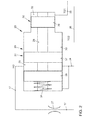
- the pressure reduction valve 21 has a stepped piston 39 and a likewise stepped cylinder 40.
- the stepped piston 39 has three sections 41, 42, 43, each with a different diameter.
- the stepped piston 39 has two piston regions 44, 45, which are adapted to the inner diameter of the portion 41. Between the two piston regions 44, 45, a diaphragm space 46 is formed.
- the diaphragm chamber 46 or the piston regions 44, 45 connects or blocks the connection between the main pressure channel 17 and the tank line 24.
- the diaphragm chamber 46 is formed by an annular space between the two piston regions 44, 45.
- the stepped piston 39 further has a piston region 47, wherein the piston region 47 is adapted to the inner diameter of the portion 42.
- a reaction space 49 is limited, wherein the effective space 49 is functionally effectively connected to the first subsystem pressure channel 25.
- a piston portion 50 is associated with the portion 43 of correspondingly adapted diameter.
- the piston area 50 and the section 43 and the end face of a step 51 define a second active space 52, wherein the active space 52 is functionally effectively connected to the subsystem pressure channel 26.
- the annular surfaces on the steps 48, 51 are of different sizes. The difference of the annular surfaces causes when pressurized from the subsystems 22, 23 also a force on the stepped piston 39. As far as the pressure in one of the two subsystem pressure channels 25, 26 exceeds a minimum pressure, the resulting force from one of the Wirksammlung 49, 52 or from both Wirkopathic 49, 52 greater than the spring force and this leads to the displacement of the stepped piston 39 against a spring 53. As a result, the aperture space 46 is displaced so that the piston portion 44 closes the connection between the tank line 24 and the main pressure channel 17.
- the Wirksammlung 49, 52 may be connected to each other via a narrow annular gap, whereby a low oil exchange at different pressure levels in the partial transmissions is. This also does not result in an increase in the system leakage, since the system leakage is compensated by the sub-transmission valves VP1 and VP2.
- both partial transmission valves VP1 and VP2 are constantly open.
- the partial transmission valves VP1, VP2 close either when the "ignition is off", or in case of an error in one of the subsystems 22, 23, in which case only the respective associated partial transmission valve VP1 or VP2 closes.
- the pressure in the subsystems 22, 23 or in the subsystem pressure channels 25, 26 may vary.
- the subsystem pressure in the subsystem pressure channels 25, 26 each has a certain pressure.
- the respective pressure reduction valve 20 or 21 is set so that the tank line 24, even if, for example, the first partial transmission is switched off and the pressure in the second partial transmission is at least the minimum pressure (or greater) remains closed.
- the pressure reduction valve 20 or 21 may be formed either two-stage or three-stage.
- the adjacent to the aperture space 35 and 46 surfaces are particularly finely processed.
- the diaphragm, ie this region of the pressure reduction valve 20 or 21 can be designed as a conical or ball valve or the differential piston can be connected to such a valve or actuate such a valve.
- the other sections 30 and 42, 43 can be inexpensively sealed by O-rings.
- the finely worked Surfaces are smaller in the three-stage pressure reduction valve 21 than in the two-stage pressure reduction valve 20th
- the presented here mechanical solution of the pressure reduction valves 20, 21 is inexpensive and easy to manufacture.
- the pressure reduction valve 20, 21 is additionally electrically operated to z. B. to prevent the pressure drop as needed in certain situations.
- an electrical supply line or a corresponding control instruction of a control unit is necessary.
Landscapes
- Engineering & Computer Science (AREA)
- General Engineering & Computer Science (AREA)
- Mechanical Engineering (AREA)
- Physics & Mathematics (AREA)
- Fluid Mechanics (AREA)
- Fluid-Pressure Circuits (AREA)
- Hydraulic Clutches, Magnetic Clutches, Fluid Clutches, And Fluid Joints (AREA)
- Gear-Shifting Mechanisms (AREA)
Applications Claiming Priority (1)
| Application Number | Priority Date | Filing Date | Title |
|---|---|---|---|
| DE102012007124A DE102012007124A1 (de) | 2012-04-07 | 2012-04-07 | Hydraulische Steuerungsvorrichtung |
Publications (3)
| Publication Number | Publication Date |
|---|---|
| EP2647883A2 true EP2647883A2 (fr) | 2013-10-09 |
| EP2647883A3 EP2647883A3 (fr) | 2017-09-13 |
| EP2647883B1 EP2647883B1 (fr) | 2019-08-21 |
Family
ID=48044591
Family Applications (1)
| Application Number | Title | Priority Date | Filing Date |
|---|---|---|---|
| EP13160813.5A Active EP2647883B1 (fr) | 2012-04-07 | 2013-03-25 | Dispositif de commande hydraulique |
Country Status (2)
| Country | Link |
|---|---|
| EP (1) | EP2647883B1 (fr) |
| DE (1) | DE102012007124A1 (fr) |
Cited By (4)
| Publication number | Priority date | Publication date | Assignee | Title |
|---|---|---|---|---|
| CN104595255A (zh) * | 2014-12-30 | 2015-05-06 | 吉林大学 | 游梁式抽油机液压辅助动力节能系统 |
| WO2016066515A1 (fr) * | 2014-10-27 | 2016-05-06 | Avl Commercial Driveline & Tractor Engineering Gmbh | Circuit hydraulique et procédé de commande d'un circuit hydraulique |
| WO2017186710A1 (fr) * | 2016-04-26 | 2017-11-02 | Avl Commercial Driveline & Tractor Engineering Gmbh | Circuit hydraulique, dispositif de transmission de couple muni d'un circuit hydraulique, procédé permettant de faire fonctionner un circuit hydraulique |
| CN115681478A (zh) * | 2021-07-22 | 2023-02-03 | 上海汽车集团股份有限公司 | 双离合变速箱的电液执行系统 |
Families Citing this family (1)
| Publication number | Priority date | Publication date | Assignee | Title |
|---|---|---|---|---|
| DE102019211854A1 (de) * | 2019-08-07 | 2021-02-11 | Zf Friedrichshafen Ag | Ölversorgungssystem für ein Automatikgetriebe |
Family Cites Families (7)
| Publication number | Priority date | Publication date | Assignee | Title |
|---|---|---|---|---|
| US3353495A (en) | 1966-03-02 | 1967-11-21 | Caterpillar Tractor Co | Automatic accumulator bleed means |
| US3991570A (en) | 1975-09-29 | 1976-11-16 | Western Fluid Power Corporation | Hydraulic accumulator pressure release valve and system |
| DD126317A1 (fr) * | 1976-06-28 | 1977-07-06 | ||
| WO2002040886A1 (fr) * | 2000-11-17 | 2002-05-23 | Mannesmann Sachs Ag | Systeme d'embrayage |
| WO2007124790A1 (fr) * | 2006-04-26 | 2007-11-08 | Borgwarner.Inc | Dispositif hydraulique pour l'embrayage d'un véhicule automobile et son procédé de fonctionnement |
| JP4420112B2 (ja) * | 2008-01-15 | 2010-02-24 | トヨタ自動車株式会社 | 車両用同期噛合式変速機の油圧制御回路 |
| DE102008049739B4 (de) * | 2008-09-30 | 2020-07-23 | Ipgate Ag | Zentrale Druckversorgung für Nebenantriebe |
-
2012
- 2012-04-07 DE DE102012007124A patent/DE102012007124A1/de not_active Withdrawn
-
2013
- 2013-03-25 EP EP13160813.5A patent/EP2647883B1/fr active Active
Cited By (5)
| Publication number | Priority date | Publication date | Assignee | Title |
|---|---|---|---|---|
| WO2016066515A1 (fr) * | 2014-10-27 | 2016-05-06 | Avl Commercial Driveline & Tractor Engineering Gmbh | Circuit hydraulique et procédé de commande d'un circuit hydraulique |
| CN104595255A (zh) * | 2014-12-30 | 2015-05-06 | 吉林大学 | 游梁式抽油机液压辅助动力节能系统 |
| WO2017186710A1 (fr) * | 2016-04-26 | 2017-11-02 | Avl Commercial Driveline & Tractor Engineering Gmbh | Circuit hydraulique, dispositif de transmission de couple muni d'un circuit hydraulique, procédé permettant de faire fonctionner un circuit hydraulique |
| US11015707B2 (en) | 2016-04-26 | 2021-05-25 | Avl Commercial Driveline & Tractor Engineering Gmbh | Hydraulic circuit, torque transmission device having a hydraulic circuit, and method for operating a hydraulic circuit |
| CN115681478A (zh) * | 2021-07-22 | 2023-02-03 | 上海汽车集团股份有限公司 | 双离合变速箱的电液执行系统 |
Also Published As
| Publication number | Publication date |
|---|---|
| DE102012007124A1 (de) | 2013-10-10 |
| EP2647883A3 (fr) | 2017-09-13 |
| EP2647883B1 (fr) | 2019-08-21 |
Similar Documents
| Publication | Publication Date | Title |
|---|---|---|
| DE102012200202B4 (de) | Hydraulische Schaltvorrichtung für ein Automatikgetriebe | |
| EP1596104B1 (fr) | Dispositif de commande de plusieurs cylindres de passage et système d'alimentation hydraulique pour une boite à double embrayages | |
| EP1994310A1 (fr) | Commande hydraulique destinée à une transmission à embrayage double | |
| DE102011104530A1 (de) | Hydraulische Stellanordnung | |
| DE102013212947A1 (de) | Hydraulische Steuerungseinrichtung für ein Automatikgetriebe | |
| EP1469235A1 (fr) | Systeme de controle et régulation hydraulique et méthode de réglage des niveaux de pression hydraulique | |
| DE10338355A1 (de) | Doppelkupplungsgetriebe mit Zustandshaltefunktion | |
| DE102013221035A1 (de) | Hydraulische Steuerungsvorrichtung für ein Automatikgetriebe | |
| DE102011085255A1 (de) | Zapfwellengetriebe | |
| EP2647883B1 (fr) | Dispositif de commande hydraulique | |
| EP3093532B1 (fr) | Systeme hydraulique de vehicule automobile | |
| EP1903238B1 (fr) | Système hydraulique | |
| WO2015036076A1 (fr) | Dispositif de commande pour effectuer sélectivement une connexion fluidique et une déconnexion de points de raccordement fluidique | |
| DE102013001928A1 (de) | Kraftfahrzeuggetriebevorrichtung mit einem Hydrauliksystem | |
| DE102005019516A1 (de) | Vorrichtung zum Ansteuern einer Mehrzahl von hydraulischen Schaltzylindern sowie Hydraulikversorgungssystem für ein Doppelkupplungsgetriebe | |
| DE102012022086B4 (de) | Hydraulische Steuerungsvorrichtung | |
| EP1635092B1 (fr) | Dispositif hydraulique de contrôle pour une fourchette dans une boîte de vitesses | |
| EP2929217B1 (fr) | Dispositif destiné à commander le fonctionnement d'un ventilateur appartenant à un système de refroidissement et pouvant être entraîné par un moteur hydraulique | |
| EP3477159A1 (fr) | Système hydraulique pour une transmission de véhicule automobile | |
| DE2212679B2 (de) | Hydraulische Schaltvorrichtung für Lastschaltgetriebe mit Sicherung gegen Fehlschaltungen | |
| DE102022101020A1 (de) | Hydrauliksystem und Verfahren zum Betreiben eines Hydrauliksystems | |
| DE102016212306A1 (de) | Zwischenblock und Kompaktachse mit einem Zwischenblock | |
| DE102020004389A1 (de) | Hydrauliksystem für ein Doppelkupplungsgetriebe | |
| DE102012212857A1 (de) | Hydraulischer Nockenwellenversteller mit drehzahlabhängiger Druckübersetzung | |
| DE102010038078B4 (de) | Hydraulische Parksperre und Verfahren zum Schalten einer solchen |
Legal Events
| Date | Code | Title | Description |
|---|---|---|---|
| PUAI | Public reference made under article 153(3) epc to a published international application that has entered the european phase |
Free format text: ORIGINAL CODE: 0009012 |
|
| AK | Designated contracting states |
Kind code of ref document: A2 Designated state(s): AL AT BE BG CH CY CZ DE DK EE ES FI FR GB GR HR HU IE IS IT LI LT LU LV MC MK MT NL NO PL PT RO RS SE SI SK SM TR |
|
| AX | Request for extension of the european patent |
Extension state: BA ME |
|
| PUAL | Search report despatched |
Free format text: ORIGINAL CODE: 0009013 |
|
| AK | Designated contracting states |
Kind code of ref document: A3 Designated state(s): AL AT BE BG CH CY CZ DE DK EE ES FI FR GB GR HR HU IE IS IT LI LT LU LV MC MK MT NL NO PL PT RO RS SE SI SK SM TR |
|
| AX | Request for extension of the european patent |
Extension state: BA ME |
|
| RIC1 | Information provided on ipc code assigned before grant |
Ipc: F15B 1/027 20060101ALI20170809BHEP Ipc: F16H 61/00 20060101AFI20170809BHEP |
|
| STAA | Information on the status of an ep patent application or granted ep patent |
Free format text: STATUS: REQUEST FOR EXAMINATION WAS MADE |
|
| 17P | Request for examination filed |
Effective date: 20180313 |
|
| RBV | Designated contracting states (corrected) |
Designated state(s): AL AT BE BG CH CY CZ DE DK EE ES FI FR GB GR HR HU IE IS IT LI LT LU LV MC MK MT NL NO PL PT RO RS SE SI SK SM TR |
|
| GRAP | Despatch of communication of intention to grant a patent |
Free format text: ORIGINAL CODE: EPIDOSNIGR1 |
|
| STAA | Information on the status of an ep patent application or granted ep patent |
Free format text: STATUS: GRANT OF PATENT IS INTENDED |
|
| INTG | Intention to grant announced |
Effective date: 20190403 |
|
| GRAS | Grant fee paid |
Free format text: ORIGINAL CODE: EPIDOSNIGR3 |
|
| GRAA | (expected) grant |
Free format text: ORIGINAL CODE: 0009210 |
|
| STAA | Information on the status of an ep patent application or granted ep patent |
Free format text: STATUS: THE PATENT HAS BEEN GRANTED |
|
| AK | Designated contracting states |
Kind code of ref document: B1 Designated state(s): AL AT BE BG CH CY CZ DE DK EE ES FI FR GB GR HR HU IE IS IT LI LT LU LV MC MK MT NL NO PL PT RO RS SE SI SK SM TR |
|
| REG | Reference to a national code |
Ref country code: GB Ref legal event code: FG4D Free format text: NOT ENGLISH |
|
| REG | Reference to a national code |
Ref country code: CH Ref legal event code: EP |
|
| REG | Reference to a national code |
Ref country code: DE Ref legal event code: R096 Ref document number: 502013013393 Country of ref document: DE |
|
| REG | Reference to a national code |
Ref country code: AT Ref legal event code: REF Ref document number: 1170136 Country of ref document: AT Kind code of ref document: T Effective date: 20190915 |
|
| REG | Reference to a national code |
Ref country code: IE Ref legal event code: FG4D Free format text: LANGUAGE OF EP DOCUMENT: GERMAN |
|
| REG | Reference to a national code |
Ref country code: LT Ref legal event code: MG4D |
|
| REG | Reference to a national code |
Ref country code: NL Ref legal event code: MP Effective date: 20190821 |
|
| PG25 | Lapsed in a contracting state [announced via postgrant information from national office to epo] |
Ref country code: SE Free format text: LAPSE BECAUSE OF FAILURE TO SUBMIT A TRANSLATION OF THE DESCRIPTION OR TO PAY THE FEE WITHIN THE PRESCRIBED TIME-LIMIT Effective date: 20190821 Ref country code: BG Free format text: LAPSE BECAUSE OF FAILURE TO SUBMIT A TRANSLATION OF THE DESCRIPTION OR TO PAY THE FEE WITHIN THE PRESCRIBED TIME-LIMIT Effective date: 20191121 Ref country code: NO Free format text: LAPSE BECAUSE OF FAILURE TO SUBMIT A TRANSLATION OF THE DESCRIPTION OR TO PAY THE FEE WITHIN THE PRESCRIBED TIME-LIMIT Effective date: 20191121 Ref country code: PT Free format text: LAPSE BECAUSE OF FAILURE TO SUBMIT A TRANSLATION OF THE DESCRIPTION OR TO PAY THE FEE WITHIN THE PRESCRIBED TIME-LIMIT Effective date: 20191223 Ref country code: HR Free format text: LAPSE BECAUSE OF FAILURE TO SUBMIT A TRANSLATION OF THE DESCRIPTION OR TO PAY THE FEE WITHIN THE PRESCRIBED TIME-LIMIT Effective date: 20190821 Ref country code: LT Free format text: LAPSE BECAUSE OF FAILURE TO SUBMIT A TRANSLATION OF THE DESCRIPTION OR TO PAY THE FEE WITHIN THE PRESCRIBED TIME-LIMIT Effective date: 20190821 Ref country code: NL Free format text: LAPSE BECAUSE OF FAILURE TO SUBMIT A TRANSLATION OF THE DESCRIPTION OR TO PAY THE FEE WITHIN THE PRESCRIBED TIME-LIMIT Effective date: 20190821 Ref country code: FI Free format text: LAPSE BECAUSE OF FAILURE TO SUBMIT A TRANSLATION OF THE DESCRIPTION OR TO PAY THE FEE WITHIN THE PRESCRIBED TIME-LIMIT Effective date: 20190821 |
|
| PG25 | Lapsed in a contracting state [announced via postgrant information from national office to epo] |
Ref country code: LV Free format text: LAPSE BECAUSE OF FAILURE TO SUBMIT A TRANSLATION OF THE DESCRIPTION OR TO PAY THE FEE WITHIN THE PRESCRIBED TIME-LIMIT Effective date: 20190821 Ref country code: RS Free format text: LAPSE BECAUSE OF FAILURE TO SUBMIT A TRANSLATION OF THE DESCRIPTION OR TO PAY THE FEE WITHIN THE PRESCRIBED TIME-LIMIT Effective date: 20190821 Ref country code: GR Free format text: LAPSE BECAUSE OF FAILURE TO SUBMIT A TRANSLATION OF THE DESCRIPTION OR TO PAY THE FEE WITHIN THE PRESCRIBED TIME-LIMIT Effective date: 20191122 Ref country code: ES Free format text: LAPSE BECAUSE OF FAILURE TO SUBMIT A TRANSLATION OF THE DESCRIPTION OR TO PAY THE FEE WITHIN THE PRESCRIBED TIME-LIMIT Effective date: 20190821 Ref country code: IS Free format text: LAPSE BECAUSE OF FAILURE TO SUBMIT A TRANSLATION OF THE DESCRIPTION OR TO PAY THE FEE WITHIN THE PRESCRIBED TIME-LIMIT Effective date: 20191221 Ref country code: AL Free format text: LAPSE BECAUSE OF FAILURE TO SUBMIT A TRANSLATION OF THE DESCRIPTION OR TO PAY THE FEE WITHIN THE PRESCRIBED TIME-LIMIT Effective date: 20190821 |
|
| PG25 | Lapsed in a contracting state [announced via postgrant information from national office to epo] |
Ref country code: TR Free format text: LAPSE BECAUSE OF FAILURE TO SUBMIT A TRANSLATION OF THE DESCRIPTION OR TO PAY THE FEE WITHIN THE PRESCRIBED TIME-LIMIT Effective date: 20190821 |
|
| PG25 | Lapsed in a contracting state [announced via postgrant information from national office to epo] |
Ref country code: DK Free format text: LAPSE BECAUSE OF FAILURE TO SUBMIT A TRANSLATION OF THE DESCRIPTION OR TO PAY THE FEE WITHIN THE PRESCRIBED TIME-LIMIT Effective date: 20190821 Ref country code: EE Free format text: LAPSE BECAUSE OF FAILURE TO SUBMIT A TRANSLATION OF THE DESCRIPTION OR TO PAY THE FEE WITHIN THE PRESCRIBED TIME-LIMIT Effective date: 20190821 Ref country code: IT Free format text: LAPSE BECAUSE OF FAILURE TO SUBMIT A TRANSLATION OF THE DESCRIPTION OR TO PAY THE FEE WITHIN THE PRESCRIBED TIME-LIMIT Effective date: 20190821 Ref country code: RO Free format text: LAPSE BECAUSE OF FAILURE TO SUBMIT A TRANSLATION OF THE DESCRIPTION OR TO PAY THE FEE WITHIN THE PRESCRIBED TIME-LIMIT Effective date: 20190821 Ref country code: PL Free format text: LAPSE BECAUSE OF FAILURE TO SUBMIT A TRANSLATION OF THE DESCRIPTION OR TO PAY THE FEE WITHIN THE PRESCRIBED TIME-LIMIT Effective date: 20190821 |
|
| PG25 | Lapsed in a contracting state [announced via postgrant information from national office to epo] |
Ref country code: SK Free format text: LAPSE BECAUSE OF FAILURE TO SUBMIT A TRANSLATION OF THE DESCRIPTION OR TO PAY THE FEE WITHIN THE PRESCRIBED TIME-LIMIT Effective date: 20190821 Ref country code: IS Free format text: LAPSE BECAUSE OF FAILURE TO SUBMIT A TRANSLATION OF THE DESCRIPTION OR TO PAY THE FEE WITHIN THE PRESCRIBED TIME-LIMIT Effective date: 20200224 Ref country code: CZ Free format text: LAPSE BECAUSE OF FAILURE TO SUBMIT A TRANSLATION OF THE DESCRIPTION OR TO PAY THE FEE WITHIN THE PRESCRIBED TIME-LIMIT Effective date: 20190821 Ref country code: SM Free format text: LAPSE BECAUSE OF FAILURE TO SUBMIT A TRANSLATION OF THE DESCRIPTION OR TO PAY THE FEE WITHIN THE PRESCRIBED TIME-LIMIT Effective date: 20190821 |
|
| REG | Reference to a national code |
Ref country code: DE Ref legal event code: R097 Ref document number: 502013013393 Country of ref document: DE |
|
| PLBE | No opposition filed within time limit |
Free format text: ORIGINAL CODE: 0009261 |
|
| STAA | Information on the status of an ep patent application or granted ep patent |
Free format text: STATUS: NO OPPOSITION FILED WITHIN TIME LIMIT |
|
| PG2D | Information on lapse in contracting state deleted |
Ref country code: IS |
|
| 26N | No opposition filed |
Effective date: 20200603 |
|
| PG25 | Lapsed in a contracting state [announced via postgrant information from national office to epo] |
Ref country code: SI Free format text: LAPSE BECAUSE OF FAILURE TO SUBMIT A TRANSLATION OF THE DESCRIPTION OR TO PAY THE FEE WITHIN THE PRESCRIBED TIME-LIMIT Effective date: 20190821 |
|
| PG25 | Lapsed in a contracting state [announced via postgrant information from national office to epo] |
Ref country code: MC Free format text: LAPSE BECAUSE OF FAILURE TO SUBMIT A TRANSLATION OF THE DESCRIPTION OR TO PAY THE FEE WITHIN THE PRESCRIBED TIME-LIMIT Effective date: 20190821 |
|
| REG | Reference to a national code |
Ref country code: CH Ref legal event code: PL |
|
| REG | Reference to a national code |
Ref country code: BE Ref legal event code: MM Effective date: 20200331 |
|
| PG25 | Lapsed in a contracting state [announced via postgrant information from national office to epo] |
Ref country code: LU Free format text: LAPSE BECAUSE OF NON-PAYMENT OF DUE FEES Effective date: 20200325 |
|
| PG25 | Lapsed in a contracting state [announced via postgrant information from national office to epo] |
Ref country code: FR Free format text: LAPSE BECAUSE OF NON-PAYMENT OF DUE FEES Effective date: 20200331 Ref country code: IE Free format text: LAPSE BECAUSE OF NON-PAYMENT OF DUE FEES Effective date: 20200325 Ref country code: CH Free format text: LAPSE BECAUSE OF NON-PAYMENT OF DUE FEES Effective date: 20200331 Ref country code: LI Free format text: LAPSE BECAUSE OF NON-PAYMENT OF DUE FEES Effective date: 20200331 |
|
| PG25 | Lapsed in a contracting state [announced via postgrant information from national office to epo] |
Ref country code: BE Free format text: LAPSE BECAUSE OF NON-PAYMENT OF DUE FEES Effective date: 20200331 |
|
| GBPC | Gb: european patent ceased through non-payment of renewal fee |
Effective date: 20200325 |
|
| PG25 | Lapsed in a contracting state [announced via postgrant information from national office to epo] |
Ref country code: GB Free format text: LAPSE BECAUSE OF NON-PAYMENT OF DUE FEES Effective date: 20200325 |
|
| REG | Reference to a national code |
Ref country code: AT Ref legal event code: MM01 Ref document number: 1170136 Country of ref document: AT Kind code of ref document: T Effective date: 20200325 |
|
| PG25 | Lapsed in a contracting state [announced via postgrant information from national office to epo] |
Ref country code: AT Free format text: LAPSE BECAUSE OF NON-PAYMENT OF DUE FEES Effective date: 20200325 |
|
| PG25 | Lapsed in a contracting state [announced via postgrant information from national office to epo] |
Ref country code: MT Free format text: LAPSE BECAUSE OF FAILURE TO SUBMIT A TRANSLATION OF THE DESCRIPTION OR TO PAY THE FEE WITHIN THE PRESCRIBED TIME-LIMIT Effective date: 20190821 Ref country code: CY Free format text: LAPSE BECAUSE OF FAILURE TO SUBMIT A TRANSLATION OF THE DESCRIPTION OR TO PAY THE FEE WITHIN THE PRESCRIBED TIME-LIMIT Effective date: 20190821 |
|
| PG25 | Lapsed in a contracting state [announced via postgrant information from national office to epo] |
Ref country code: MK Free format text: LAPSE BECAUSE OF FAILURE TO SUBMIT A TRANSLATION OF THE DESCRIPTION OR TO PAY THE FEE WITHIN THE PRESCRIBED TIME-LIMIT Effective date: 20190821 |
|
| P01 | Opt-out of the competence of the unified patent court (upc) registered |
Effective date: 20230523 |
|
| PGFP | Annual fee paid to national office [announced via postgrant information from national office to epo] |
Ref country code: DE Payment date: 20260331 Year of fee payment: 14 |