EP2647953B1 - Déphaseur à quatre-vingt-dix degrés précis - Google Patents
Déphaseur à quatre-vingt-dix degrés précis Download PDFInfo
- Publication number
- EP2647953B1 EP2647953B1 EP13001692.6A EP13001692A EP2647953B1 EP 2647953 B1 EP2647953 B1 EP 2647953B1 EP 13001692 A EP13001692 A EP 13001692A EP 2647953 B1 EP2647953 B1 EP 2647953B1
- Authority
- EP
- European Patent Office
- Prior art keywords
- circuit
- input
- output
- amplifier circuit
- signal
- Prior art date
- Legal status (The legal status is an assumption and is not a legal conclusion. Google has not performed a legal analysis and makes no representation as to the accuracy of the status listed.)
- Active
Links
Images


Classifications
-
- H—ELECTRICITY
- H02—GENERATION; CONVERSION OR DISTRIBUTION OF ELECTRIC POWER
- H02J—ELECTRIC POWER NETWORKS; CIRCUIT ARRANGEMENTS OR SYSTEMS FOR SUPPLYING OR DISTRIBUTING ELECTRIC POWER; SYSTEMS FOR STORING ELECTRIC ENERGY
- H02J4/00—Circuit arrangements for mains or distribution networks not specified as AC or DC; Circuit arrangements for mains or distribution networks combining AC and DC sections or sub-networks
-
- G—PHYSICS
- G01—MEASURING; TESTING
- G01C—MEASURING DISTANCES, LEVELS OR BEARINGS; SURVEYING; NAVIGATION; GYROSCOPIC INSTRUMENTS; PHOTOGRAMMETRY OR VIDEOGRAMMETRY
- G01C19/00—Gyroscopes; Turn-sensitive devices using vibrating masses; Turn-sensitive devices without moving masses; Measuring angular rate using gyroscopic effects
- G01C19/56—Turn-sensitive devices using vibrating masses, e.g. vibratory angular rate sensors based on Coriolis forces
- G01C19/5776—Signal processing not specific to any of the devices covered by groups G01C19/5607 - G01C19/5719
Definitions
- Micro-electromechanical systems include small mechanical devices performing electrical and mechanical functions that are fabricated using photolithography techniques similar to techniques used to fabricate integrated circuits. Some MEMS devices are sensors that can detect motion such as an accelerometer or detect angular rate such as a gyroscope.
- MEMS gyroscopes have become widely available and multi-axis gyroscope MEMS structures can be integrated into one device.
- the size and complexity of MEMS gyroscope sensors can still be considered excessive in certain applications, such as personal or mobile electronic devices.
- the demand for three axis acceleration detection in consumer/mobile, automotive and aerospace/defense applications is constantly increasing. Consequently, it is desirable to reduce the size and complexity of drive and sense electronics for MEMS gyroscopes.
- EP 1 521 086 A1 discloses an inertial sensor which supplies a diagnostic signal to detect an abnormality in a detection circuit or detection element.
- US 2010/0206074 A1 discloses an oscillation drive device and a physical quantity measurement device.
- EP 1 460 380 A1 discloses a system exciting a driving vibration in a vibrator.
- An apparatus example includes a drive signal circuit for MEMS sensor.
- the drive signal circuit includes an input configured to receive a voltage signal representative of charge generated by the MEMS sensor, a phase-shift circuit electrically coupled to the input and configured to phase shift an input signal by substantially ninety degrees, and a comparator circuit with hysteresis.
- An input of the comparator is electrically coupled to an output of the phase-shift circuit and an output of the comparator circuit is electrically coupled to an output of the drive signal circuit.
- a feedback loop extends from the output of the drive signal circuit to the input of the phase-shift circuit, wherein the feedback loop is configured to generate a self-oscillating signal at an output of the drive signal circuit.
- An output signal generated by the drive signal circuit is applied to a drive input of the MEMS sensor.
- FIG. 1 is a block diagram of portions of an example of an electronic system that includes a MEMS sensor 105 and an IC 110.
- the MEMS sensor can include a MEMS gyroscope, such as a vibratory gyroscope for example.
- a vibratory gyroscope can include a proof mass that is suspended above a substrate. The proof mass oscillates mechanically in a drive direction and in a sense direction orthogonal to the drive direction. The proof mass is driven into resonance in the drive direction by an external drive source.
- the gyroscope is subjected to an angular rotation, a Coriolis force is induced in the sense direction that is detected using sense capacitors.
- the capacitors gdp and gdn represent the drive input to the MEMS sensor 105 and capacitors gp and gn represent the sense signal output of the MEMS sensor 105.
- the IC 110 includes circuits configured or designed to maintain the mechanical oscillation of the MEMS sensor 105 to a target mechanical oscillation.
- the circuits include a charge-to-voltage converter circuit 115 (C2V) and a sensor drive amplifier circuit 120.
- C2V charge-to-voltage converter circuit 115
- the sensor drive amplifier circuit 120 provides an electrostatic force to the sensor to cause mechanical oscillation.
- the IC 110 also includes an automatic gain control (AGC) circuit 125 and a drive signal circuit 130.
- the AGC circuit 125 adjusts the electrostatic force to maintain the mechanical oscillation to a target value.
- the drive signal circuit 130 provides a reference drive signal to the sensor drive amplifier circuit 120.
- the reference drive signal can be based on the signal sensed from the MEMS sensor 105. Because sensing by the MEMS sensor is ninety degrees out of phase with the driving of the MEMS sensor, the sensed signal is phased shifted by substantially ninety degrees to generate the reference drive signal. However, when the electronic system first starts up or powers up, there is no drive signal available for the MEMS sensor 105 and consequently no sense signal from the MEMS sensor 105 with which to create a reference drive signal.
- the drive signal circuit 130 To create an initial reference drive signal, the drive signal circuit 130 generates an oscillating signal upon power up. Thus, a drive signal can be provided to the sensor drive amplifier circuit 120 even when a sense signal from the MEMS sensor 105 is not present. This oscillating signal causes mechanical oscillation in the MEMS sensor 105 which in turn creates charge and generates a sense signal at the output of the C2V circuit.
- the initial drive signal can include multiple harmonic frequencies. When the generated sense signal reaches a threshold amplitude the reference drive signal is locked to the frequency of the generated sense signal.
- the sense signal generated by the MEMS sensor is a high-Q signal due to the mechanical resonance of the MEMS sensor 105, and using this signal results in results in a high Q reference drive signal.
- FIG. 2 is a flow diagram of a method 200 of generating a drive signal for a MEMS sensor, such as a MEMS gyroscope or gyro for example.
- a MEMS sensor such as a MEMS gyroscope or gyro for example.
- an oscillating signal is self-generated by a drive signal circuit at the output of the drive signal circuit.
- the oscillating signal is applied to a drive input of the MEMS sensor.
- a voltage signal representative of charge generated by the MEMS sensor is received at an input of the drive signal circuit.
- the phase of the received voltage signal is shifted by substantially ninety degrees and the phase shifted signal is used to generate the drive signal instead of using the self-generated signal.
- the generated drive signal is applied to the drive input of the MEMS sensor.
- FIG. 3 is a circuit diagram of portions of an example of a drive signal circuit.
- the drive signal circuit provides a reference drive signal for the MEMS sensor.
- the drive signal circuit includes an input 335 that receives a voltage signal representative of charge generated by the MEMS sensor.
- the voltage signal is received from a charge-to-voltage converter circuit.
- the drive signal circuit also includes a phase-shift circuit 340 and a comparator circuit 345.
- the phase-shift circuit 340 can be electrically coupled to the input 335.
- the phase shift circuit 340 shifts the phase of an input signal by substantially ninety degrees (90°).
- the phase shift circuit 340 includes an integrator circuit.
- the comparator circuit 345 has hysteresis. The output of the comparator circuit 345 transitions from low to high when the input is greater than a first threshold, and the output transitions from high to low when the input is less than a second threshold that is different from the first threshold.
- the input of the comparator circuit 345 can be electrically coupled to the output of the phase-shift circuit 340, and the output of the comparator circuit 345 can be electrically coupled to the output 350 of the drive signal circuit.
- the drive signal circuit includes a feedback loop that extends from the output of the drive signal circuit to an input of the phase-shift circuit 340.
- the feedback loop can be electrically coupled from the output of the comparator circuit 345 to an input of an amplifier circuit 355 of the integrator circuit.
- the feedback loop can include a first transconductance amplifier circuit 360 (sometimes called an operational transconductance amplifier or OTA) having an input electrically coupled to the output of the comparator circuit 350, a second transconductance amplifier circuit 365 having an input electrically coupled to an output of the first transconductance amplifier circuit 360 and an output electrically coupled to an input of the phase-shift circuit 340.
- the feedback loop can include a capacitor 370 (C1) coupled to the output of the first transconductance amplifier circuit 360 and circuit ground.
- the configuration of the feedback loop self-generates an oscillating signal or a self-oscillating signal at the output 350 of the drive signal circuit.
- the hysteretic comparator circuit maintains minimal amplitude of oscillation in the loop (at the integrator output) and controls the range of the self oscillation frequency.
- the binary output of the comparator charges/discharge the capacitor 370 through the first transconductance amplifier circuit 360.
- the error in the self-oscillating signal from a 50% duty cycle is stored onto the capacitor 370 and fed back to the phase-shift circuit 340 though the second transconductance amplifier circuit 365.
- This feedback arrangement corrects input signal offsets, amplifier offsets, and comparator offsets to provide a substantially 50% duty cycle output signal.
- Output signals generated by the drive signal circuit are applied to a drive input of the MEMS sensor.
- the output signal provided as the reference drive signal can be a signal at drive circuit output 350 (OUT) or a signal at the output of the phase-shift circuit 340 (OUT-SINEWAVE).
- the self oscillating signal of the drive signal circuit is selected by the AGC circuit 125 as the reference drive signal for the drive amplifier circuit 120 upon start-up. This self-generated oscillating signal is available at the circuit node labeled OUT in the drive signal circuit.
- the AGC circuit 125 may switch the reference drive signal from the signal available at OUT to the signal available at OUT-SINEWAVE as the reference drive signal. This is because after the amplitude threshold is achieved, the OUT-SINEWAVE provides a more harmonically pure (e.g., higher Q) reference drive signal for the MEMS sensor.
- the high-Q signal results in improved drive and mechanical resonance in the MEMS sensor due to fewer harmonic frequencies.
- the high Q signal at OUT-SINEWAVE provides an accurate 90 degree phase shift and a substantially 50% duty cycle.
- the feedback arrangement provides a stable operating point for the forward path integrator.
- the stable operating point avoids run-away problems that can result from integrating small offsets.
- using an amplifier circuit 355 having a controlled signal gain for direct current (DC) signals minimizes the frequency shift of the self-oscillating signal over temperature.
- the feedback path should be designed to provide a large enough DC current to compensate for input signal offsets, but should have a very low alternating current (AC) gain to not disturb the ninety degree phase shift provided by the forward path integrator.
- AC alternating current
- FIG. 4 is a circuit diagram of portions of another example of a drive signal circuit having a feedback loop that includes a first transconductance amplifier circuit 460 and a second transconductance amplifier circuit 465.
- the drive signal circuit includes a current divider circuit 475 electrically coupled to the output of the second transconductance amplifier circuit 465 to divide the output current of the second transconductance amplifier circuit 465.
- FIG. 5 is a circuit diagram of portions of another example of a drive signal circuit having a feedback loop that includes a first transconductance amplifier circuit 560 and a second transconductance amplifier circuit 565.
- the drive signal circuit includes a resistive divider circuit 575 electrically coupled to the output of the second transconductance amplifier circuit 565 and the input of the phase-shift circuit 540 to divide the output current of the second transconductance amplifier circuit 565.
- FIG. 6 is a circuit diagram of portions of another example of a drive signal circuit having a feedback loop that includes a first transconductance amplifier circuit 660 and a second transconductance amplifier circuit 665.
- the second transconductance amplifier circuit 665 has an input electrically coupled to an output of the first transconductance amplifier circuit and has an output electrically coupled to an input of the integrator amplifier circuit.
- the feedback loop also includes a resistor 680 coupled to the output of the first transconductance amplifier circuit 660 and a capacitor 670 coupled to the resistor 680 and circuit ground.
- This compensation resistor R 1 adds a zero to the feedback transfer function. This adds phase lead to improve the phase margin for high amplitude input signals.
- FIG. 7 is a circuit diagram of portions of still another example of a drive signal circuit having a feedback loop that includes a third transconductance amplifier circuit 785.
- the input of the third transconductance amplifier circuit 785 is electrically coupled to the output of a comparator circuit 745 and an input of the integrator amplifier circuit to form a second parallel feedback loop.
- This added transconductance stage eliminates the need for a large compensation resistor and can provide the effective zero to provide phase lead and improve the phase margin high amplitude input signals.
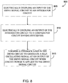
- FIG. 8 is a flow diagram of an example of a method 800 of forming a drive signal circuit for a MEMS sensor.
- an input of the drive signal circuit is electrically coupled to an input of an integrator circuit.
- the integrator circuit can have the circuit topology as shown in the examples herein.
- the output of the integrator circuit is electrically coupled to a comparator circuit having hysteresis.
- a feedback loop in the drive signal circuit is formed to generate a self-oscillating signal at an output of the drive signal circuit when circuit power is applied to the drive signal circuit.
- the feedback loop extends from the output of the comparator circuit to an input of an amplifier (e.g., an operation amplifier or opamp) of the integrator circuit.
- the integrator circuit shifts the phase angle of an input signal received at the input to the drive signal circuit by substantially ninety degrees.
- the received input signal is generated in response to applying the self-oscillating signal to a drive input of the MEMS sensor.
- the drive signal circuit can be electrically coupled to a capacitance-to-voltage converter circuit, and the input signal can be a voltage signal converted from charge generated by the MEMS sensor in response to applying the self-oscillating signal to the MEMS sensor.
- the drive signal circuit provides reliable self-startup to provide a drive oscillation signal and also reliably provides a 50% duty cycle.
- the drive signal circuit further provides an accurate 90° phase shift that avoids the noise associated with differentiator phase-shifters.
- Example 1 can include subject matter (such as an apparatus) comprising a drive signal circuit for a micro-electromechanical system (MEMS) sensor.
- the drive signal circuit includes an input configured to receive a voltage signal representative of charge generated by the MEMS sensor, a phase-shift circuit electrically coupled to the input and configured to phase shift an input signal by substantially ninety degrees, a comparator circuit with hysteresis, and a feedback loop extending from the output of the drive signal circuit to the input of the phase-shift circuit.
- the comparator circuit can be electrically coupled to an output of the phase-shift circuit, and an output of the comparator circuit is electrically coupled to an output of the drive signal circuit.
- the feedback loop can be configured to generate a self-oscillating signal at an output of the drive signal circuit, and the output signal generated by the drive signal circuit is applied to a drive input of the MEMS sensor.
- Example 2 can include, or can optionally be combined with the subject matter of Example 1 to optionally include, a first transconductance amplifier circuit having an input electrically coupled to the output of the comparator circuit, a second transconductance amplifier circuit having an input electrically coupled to an output of the first transconductance amplifier circuit and an output electrically coupled to an input of the phase-shift circuit, and a capacitor coupled to the output of the first transconductance amplifier circuit and circuit ground.
- Example 3 can include, or can optionally be combined with the subject matter of one or any combination of Examples 1 and 2 to optionally include a current divider circuit electrically coupled to the output of the second transconductance amplifier circuit.
- Example 4 can include, or can optionally be combined with the subject matter of one or any combination of Examples 1-3 to optionally include, a resistive divider circuit electrically coupled to the output of the second transconductance amplifier circuit and the input of the phase-shift circuit, wherein the resistive divider is configured to divide the output current of the second transconductance amplifier circuit.
- Example 5 can include, or can optionally be combined with the subject matter of one or any combination of Examples 1-4 to optionally include, a phase-shift circuit that includes an integrator circuit that includes an amplifier circuit, and the feedback loop optionally electrically coupled from the output of the comparator circuit to an input of the integrator amplifier circuit.
- Example 6 can include, or can optionally be combined with the subject matter of Example 5 to optionally include, an integrator amplifier circuit that provides controlled signal gain for direct current (DC) signals.
- DC direct current
- Example 7 can include, or can optionally be combined with the subject matter of one or any combination of Examples 5 and 6 to include a third transconductance amplifier circuit, and an input of the third transconductance amplifier circuit is electrically coupled to the output of the comparator circuit and an input of the integrator amplifier circuit to form a second feedback loop.
- Example 8 can include, or can optionally be combined with the subject matter of one or any combination of Examples 5-7 to optionally include a feedback loop having a first transconductance amplifier circuit having an input electrically coupled to the output of the comparator circuit, a second transconductance amplifier circuit having an input electrically coupled to an output of the first transconductance amplifier circuit and having an output electrically coupled to an input of the integrator amplifier circuit, a resistor coupled to the output of the first transconductance amplifier circuit, and a capacitor coupled to the resistor and circuit ground.
- Example 9 can include, or can optionally be combined with the subject matter of one or any combination of Examples 1-8 to optionally include, the MEMS sensor, wherein the MEMS sensor includes a MEMS gyro.
- Example 10 can include, or can optionally be combined with the subject matter of one or any combination of Examples 1-9 to include, subject matter (such as a method, a means for performing acts, or a machine readable medium including instructions that, when performed by the machine, can cause the machine to perform acts) comprising self-generating an oscillating signal at an output of a drive signal circuit and applying the oscillating signal to a drive input of the MEMS sensor, receiving, at an input of the drive signal circuit, a voltage signal representative of charge generated by the MEMS sensor in response to applying the oscillation signal to the drive input of the MEMS sensor, shifting the phase of the received voltage signal by substantially ninety degrees and using the phase shifted signal to generate the drive signal, and applying the generated drive signal to the drive input of the MEMS sensor.
- subject matter such as a method, a means for performing acts, or a machine readable medium including instructions that, when performed by the machine, can cause the machine to perform acts
- Example 11 can include, or can optionally be combined with the subject matter of Example 10 to optionally include integrating the received voltage signal using an integrator circuit.
- Example 12 can include or can optionally be combined with the subject matter of Example 11 to optionally include, applying the integrated received voltage signal to a comparator circuit with hysteresis and feeding back the output of the comparator circuit to an input of an amplifier of the integrator circuit to form a feedback loop.
- Example 13 can include, or can optionally be combined with the subject matter of Example 12 to optionally include, charging, through a first transconductance amplifier circuit, a capacitor using the output of the comparator circuit, and applying the charge of the capacitor to an input of the amplifier of the integrator circuit through a second transconductance amplifier circuit.
- Example 14 can include, or can optionally be combined with the subject matter of one or any combination of Example 13 to optionally include dividing the output current of the second transconductance amplifier circuit to reduce the transconductance of the second transconductance amplifier circuit.
- Example 15 can include, or can optionally be combined with the subject matter of one or any combination of Examples 13 and 14 to optionally include electrically coupling an output of the comparator circuit to an input of a third transconductance amplifier circuit and electrically coupling an output of the third transconductance amplifier circuit to an input of the amplifier circuit of the integrator circuit to form a second feedback loop.
- Example 16 can include, or can optionally be combined with the subject matter of one or any combination of Examples 13-15 to optionally include includes charging the capacitor through the first transconductance amplifier and a resistor.
- Example 17 can include, or can optionally be combined with the subject matter of one or any combination of Examples 11-16 to optionally include, applying the generated drive signal to a drive input of an MEMS gyro sensor.
- Example 18 can include, or can optionally be combined with the subject matter of one or any combination of Examples 1-17 to include, subject matter (such as a method, a means for performing acts, or a machine readable medium including instructions that, when performed by the machine, can cause the machine to perform acts) comprising electrically coupling an input of the drive signal circuit to an integrator circuit, electrically coupling an output of the integrator circuit to a comparator circuit having hysteresis, and forming a feedback loop in the drive circuit to generate a self-oscillating signal at an output of the drive signal circuit when circuit power is applied to the drive signal circuit, wherein the feedback loop extends from the output of the comparator circuit to an input of an amplifier of the integrator circuit.
- the integrator circuit shifts the phase angle of an input signal received at the input to the drive signal circuit by substantially ninety degrees, and the input signal is generated in response to applying the self-oscillating signal to a drive input of the MEMS sensor.
- Example 19 can include, or can optionally be combined with the subject matter of Example 18 to optionally include, electrically coupling the output of the comparator circuit to a capacitor through a first transconductance amplifier circuit and electrically coupling the capacitor to the phase-shift circuit using a second transconductance amplifier.
- Example 20 can include, or can optionally be combined with the subject matter of Example 19 to optionally include, electrically coupling a current divider circuit to the output of the second transconductance amplifier.
- Example 21 can include, or can optionally be combined with the subject matter of one or any combination of Examples 18-20 to optionally include, electrically coupling a resistive divider circuit at the input to the integrator circuit
- Example 22 can include, or can optionally be combined with the subject matter of one or any combination of Examples 18-21 to optionally include an amplifier circuit having controlled signal gain for DC signals.
- Example 23 can include, or can optionally be combined with the subject matter of one or any combination of Examples 18-22 to optionally include, electrically coupling an output of the comparator circuit to an input of a third transconductance amplifier circuit and electrically coupling an output of the third transconductance amplifier circuit to an input of the amplifier circuit of the integrator circuit to form a second feedback loop.
- Example 24 can include, or can optionally be combined with the subject matter of one or any combination of Examples 18-23 to optionally include, generating the input signal in response to applying the self-oscillating signal to a drive input of an MEMS gyro.
- Example 25 can include, or can optionally be combined with any portion or combination of portions of any one or more of Examples 1-24 to include, subject matter that can include means for performing any one or more of the functions of Examples 1-24, or a machine readable medium including instructions that, when performed by a machine, cause the machine to perform any one or more of the functions of Examples 1-24.
Landscapes
- Engineering & Computer Science (AREA)
- Signal Processing (AREA)
- Physics & Mathematics (AREA)
- General Physics & Mathematics (AREA)
- Radar, Positioning & Navigation (AREA)
- Remote Sensing (AREA)
- Power Engineering (AREA)
- Gyroscopes (AREA)
- Micromachines (AREA)
Claims (13)
- Appareil comprenant :un circuit (130) de signal d'attaque pour un capteur (105) de système micro-électromécanique MEMS, le circuit (130) de signal d'attaque comprenant :une entrée (335) configurée pour recevoir un signal de tension représentatif d'une charge générée par le capteur (105) de MEMS ;un circuit (340 ; 540) de déphasage électriquement couplé à l'entrée (335) et configuré pour déphaser un signal d'entrée de sensiblement quatre-vingt-dix degrés ;un circuit (345) de comparateur avec hystérèse, dans lequel une entrée du circuit (345) de comparateur est électriquement couplée à une sortie du circuit (340 ; 540) de déphasage et une sortie du circuit (345) de comparateur est électriquement couplée à une sortie (350) du circuit (130) de signal d'attaque ; etune boucle de rétroaction (360, 365, 370 ; 560, 565) s'étendant de la sortie du circuit (130) de signal d'attaque jusqu'à l'entrée du circuit (340 ; 540) de déphasage et configurée pour générer un signal auto-oscillant à une sortie du circuit (130) de signal d'attaque, etdans lequel un signal de sortie généré par le circuit (130) de signal d'attaque est appliqué à une entrée d'attaque du capteur (105) de MEMS,caractérisé en ce que la boucle de rétroaction (360, 365, 370 ; 560, 565) inclut un premier circuit (360 ; 560) d'amplificateur ayant une entrée électriquement couplée à la sortie du circuit (345) de comparateur, un deuxième circuit (365 ; 565) d'amplificateur ayant une entrée électriquement couplée à une sortie du premier circuit (345) d'amplificateur et une sortie électriquement couplée à une entrée du circuit (340 ; 540) de déphasage, et un condensateur (370) couplé à la sortie du premier circuit (360 ; 560) d'amplificateur et une masse de circuit.
- Appareil selon la revendication 1, dans lequel le premier circuit (360 ; 560) d'amplificateur inclut un premier circuit d'amplificateur à transconductance et le deuxième circuit (365 ; 565) d'amplificateur inclut un deuxième circuit d'amplificateur à transconductance.
- Appareil selon la revendication 2, incluant un circuit (475) de diviseur de courant électriquement couplé à la sortie du deuxième circuit (475) d'amplificateur à transconductance.
- Appareil selon la revendication 2, incluant un circuit (575) de diviseur résistif électriquement couplé à la sortie du deuxième circuit (565) d'amplificateur à transconductance et à l'entrée du circuit (540) de déphasage, dans lequel le diviseur résistif (575) est configuré pour diviser le courant de sortie du deuxième circuit (565) d'amplificateur à transconductance.
- Appareil selon l'une quelconque des revendications 1 à 4,
dans lequel le circuit (340) de déphasage inclut un circuit d'intégrateur qui inclut un circuit (355) d'amplificateur intégrateur, et
dans lequel la boucle de rétroaction (360, 365, 370) est électriquement couplée de la sortie du circuit (345) de comparateur à une entrée du circuit (355) d'amplificateur intégrateur. - Appareil selon la revendication 5, dans lequel le circuit (355) d'amplificateur intégrateur délivre un gain de signal commandé pour des signaux de courant continu (CC).
- Appareil selon la revendication 5, incluant :un troisième circuit (785) d'amplificateur à transconductance, etdans lequel une entrée du troisième circuit (785) d'amplificateur à transconductance est électriquement couplée à la sortie du circuit (745) de comparateur et à une entrée du circuit d'amplificateur intégrateur pour former une deuxième boucle de rétroaction.
- Appareil selon la revendication 5,
dans lequel la boucle de rétroaction inclut :un premier circuit (660) d'amplificateur à transconductance ayant une entrée électriquement couplée à la sortie du circuit de comparateur ;un deuxième circuit (665) d'amplificateur à transconductance ayant une entrée électriquement couplée à une sortie du premier circuit (660) d'amplificateur à transconductance et ayant une sortie électriquement couplée à une entrée du circuit d'amplificateur intégrateur ;une résistance (680) couplée à la sortie du premier circuit (660) d'amplificateur à transconductance ; etun condensateur (670) couplé à la résistance et à la masse de circuit. - Appareil selon la revendication 1, incluant le capteur (105) de MEMS, dans lequel le capteur (105) de MEMS inclut un gyro de MEMS.
- Procédé de génération de signal d'attaque pour un capteur (105) de MEMS, le procédé comprenant :l'auto-génération d'un signal oscillant à une sortie d'un circuit (130) de signal d'attaque et l'application du signal oscillant à une entrée d'attaque du capteur (105) de MEMS;la réception, à une entrée (335) du circuit (130) de signal d'attaque, d'un signal de tension représentatif d'une charge générée par le capteur (105) de MEMS en réponse à l'application du signal oscillant à l'entrée d'attaque du capteur (105) de MEMS;le déphasage du signal de tension reçu de sensiblement quatre-vingt-dix degrés et l'utilisation du signal déphasé pour générer le signal d'attaque, dans lequel le déphasage du signal de tension reçu de sensiblement quatre-vingt-dix degrés inclut l'intégration du signal de tension reçu en utilisant un circuit (340) d'intégrateur ; etl'application du signal d'attaque généré à l'entrée d'attaque du capteur (105) de MEMS,caractérisé en ce que l'auto-génération d'un signal oscillant inclut l'application du signal de tension reçu intégré à un circuit (345) de comparateur avec hystérèse et le renvoi de la sortie du circuit (345) de comparateur à une entrée d'un amplificateur du circuit (340) d'intégrateur pour former une boucle de rétroaction, et
dans lequel le renvoi de la sortie du circuit (345) de comparateur inclut le chargement, par l'intermédiaire d'un premier circuit (360) d'amplificateur, d'un condensateur (370) en utilisant la sortie du circuit (345) de comparateur et en appliquant la charge du condensateur (345) à l'entrée de l'amplificateur du circuit d'intégrateur par l'intermédiaire d'un deuxième circuit (465) d'amplificateur. - Procédé selon la revendication 10, dans lequel le renvoi de la sortie du circuit (345) de comparateur inclut : le chargement du condensateur (370) en utilisant un premier circuit (360) d'amplificateur à transconductance, et dans lequel l'application de la charge du condensateur (370) inclut l'application de la charge du condensateur (370) à l'entrée de l'amplificateur du circuit d'intégrateur par l'intermédiaire d'un deuxième circuit (365) d'amplificateur à transconductance.
- Procédé selon la revendication 11, incluant la division du courant de sortie du deuxième circuit (365) d'amplificateur à transconductance pour réduire la transconductance du deuxième circuit (365) d'amplificateur à transconductance.
- Procédé selon l'une quelconque des revendications 10 à 12, dans lequel l'application du signal d'attaque généré à l'entrée d'attaque du capteur (105) de MEMS inclut l'application du signal d'attaque généré à une entrée d'attaque d'un capteur gyro de MEMS.
Applications Claiming Priority (2)
| Application Number | Priority Date | Filing Date | Title |
|---|---|---|---|
| US201261619604P | 2012-04-03 | 2012-04-03 | |
| US13/746,016 US8754694B2 (en) | 2012-04-03 | 2013-01-21 | Accurate ninety-degree phase shifter |
Publications (2)
| Publication Number | Publication Date |
|---|---|
| EP2647953A1 EP2647953A1 (fr) | 2013-10-09 |
| EP2647953B1 true EP2647953B1 (fr) | 2017-03-15 |
Family
ID=48045245
Family Applications (1)
| Application Number | Title | Priority Date | Filing Date |
|---|---|---|---|
| EP13001692.6A Active EP2647953B1 (fr) | 2012-04-03 | 2013-04-03 | Déphaseur à quatre-vingt-dix degrés précis |
Country Status (2)
| Country | Link |
|---|---|
| US (1) | US8754694B2 (fr) |
| EP (1) | EP2647953B1 (fr) |
Families Citing this family (23)
| Publication number | Priority date | Publication date | Assignee | Title |
|---|---|---|---|---|
| US8739626B2 (en) | 2009-08-04 | 2014-06-03 | Fairchild Semiconductor Corporation | Micromachined inertial sensor devices |
| US9455354B2 (en) | 2010-09-18 | 2016-09-27 | Fairchild Semiconductor Corporation | Micromachined 3-axis accelerometer with a single proof-mass |
| CN103221331B (zh) | 2010-09-18 | 2016-02-03 | 快捷半导体公司 | 用于微机电系统的密封封装 |
| US9278845B2 (en) | 2010-09-18 | 2016-03-08 | Fairchild Semiconductor Corporation | MEMS multi-axis gyroscope Z-axis electrode structure |
| EP2616771B8 (fr) | 2010-09-18 | 2018-12-19 | Fairchild Semiconductor Corporation | Capteur inertiel monolithique 6 axes micro-usiné |
| WO2012037492A2 (fr) | 2010-09-18 | 2012-03-22 | Janusz Bryzek | Boîtier de microsystème électromécanique à puces multiples |
| WO2012037501A2 (fr) | 2010-09-18 | 2012-03-22 | Cenk Acar | Support de flexion pour réduire la quadrature pour dispositifs micro-usinés à résonance |
| WO2012040211A2 (fr) | 2010-09-20 | 2012-03-29 | Fairchild Semiconductor Corporation | Capteur de pression micro-électromécanique comprenant un condensateur de référence |
| CN103209922B (zh) | 2010-09-20 | 2014-09-17 | 快捷半导体公司 | 具有减小的并联电容的硅通孔 |
| US9062972B2 (en) | 2012-01-31 | 2015-06-23 | Fairchild Semiconductor Corporation | MEMS multi-axis accelerometer electrode structure |
| US8978475B2 (en) | 2012-02-01 | 2015-03-17 | Fairchild Semiconductor Corporation | MEMS proof mass with split z-axis portions |
| US8742964B2 (en) | 2012-04-04 | 2014-06-03 | Fairchild Semiconductor Corporation | Noise reduction method with chopping for a merged MEMS accelerometer sensor |
| US9488693B2 (en) | 2012-04-04 | 2016-11-08 | Fairchild Semiconductor Corporation | Self test of MEMS accelerometer with ASICS integrated capacitors |
| US9069006B2 (en) | 2012-04-05 | 2015-06-30 | Fairchild Semiconductor Corporation | Self test of MEMS gyroscope with ASICs integrated capacitors |
| EP2647955B8 (fr) | 2012-04-05 | 2018-12-19 | Fairchild Semiconductor Corporation | Annulation du déphasage de quadrature de dispositif MEMS |
| KR102058489B1 (ko) | 2012-04-05 | 2019-12-23 | 페어차일드 세미컨덕터 코포레이션 | 멤스 장치 프론트 엔드 전하 증폭기 |
| EP2647952B1 (fr) | 2012-04-05 | 2017-11-15 | Fairchild Semiconductor Corporation | Boucle de commande de gain automatique de dispositif MEMS pour entraînement d'amplitude mécanique |
| US9625272B2 (en) | 2012-04-12 | 2017-04-18 | Fairchild Semiconductor Corporation | MEMS quadrature cancellation and signal demodulation |
| KR101999745B1 (ko) | 2012-04-12 | 2019-10-01 | 페어차일드 세미컨덕터 코포레이션 | 미세 전자 기계 시스템 구동기 |
| DE102013014881B4 (de) | 2012-09-12 | 2023-05-04 | Fairchild Semiconductor Corporation | Verbesserte Silizium-Durchkontaktierung mit einer Füllung aus mehreren Materialien |
| FI125611B (en) * | 2014-02-12 | 2015-12-15 | Murata Manufacturing Co | Traction circuit for activating the MEMS resonator |
| JP6219545B1 (ja) * | 2017-03-10 | 2017-10-25 | 住友精密工業株式会社 | 振動型角速度センサ |
| US10901021B2 (en) * | 2018-02-27 | 2021-01-26 | Applied Materials, Inc. | Method for detecting wafer processing parameters with micro resonator array sensors |
Family Cites Families (126)
| Publication number | Priority date | Publication date | Assignee | Title |
|---|---|---|---|---|
| US5354695A (en) | 1992-04-08 | 1994-10-11 | Leedy Glenn J | Membrane dielectric isolation IC fabrication |
| EP0547742B1 (fr) | 1991-12-19 | 1995-12-13 | Motorola, Inc. | Accéléromètre à trois axes |
| SE9500729L (sv) | 1995-02-27 | 1996-08-28 | Gert Andersson | Anordning för mätning av vinkelhastighet i enkristallint material samt förfarande för framställning av sådan |
| US5760465A (en) | 1996-02-01 | 1998-06-02 | International Business Machines Corporation | Electronic package with strain relief means |
| JP3125675B2 (ja) | 1996-03-29 | 2001-01-22 | 三菱電機株式会社 | 容量型センサインターフェース回路 |
| US6351996B1 (en) | 1998-11-12 | 2002-03-05 | Maxim Integrated Products, Inc. | Hermetic packaging for semiconductor pressure sensors |
| US7051590B1 (en) | 1999-06-15 | 2006-05-30 | Analog Devices Imi, Inc. | Structure for attenuation or cancellation of quadrature error |
| US6522762B1 (en) | 1999-09-07 | 2003-02-18 | Microtronic A/S | Silicon-based sensor system |
| US6301965B1 (en) * | 1999-12-14 | 2001-10-16 | Sandia Corporation | Microelectromechanical accelerometer with resonance-cancelling control circuit including an idle state |
| IT1314296B1 (it) | 1999-12-21 | 2002-12-09 | St Microelectronics Srl | Struttura resistiva integrata su un substrato semiconduttore |
| US6390905B1 (en) | 2000-03-31 | 2002-05-21 | Speedfam-Ipec Corporation | Workpiece carrier with adjustable pressure zones and barriers |
| US6366468B1 (en) | 2000-04-28 | 2002-04-02 | Hewlett-Packard Company | Self-aligned common carrier |
| US6214644B1 (en) | 2000-06-30 | 2001-04-10 | Amkor Technology, Inc. | Flip-chip micromachine package fabrication method |
| US6988408B2 (en) | 2000-07-13 | 2006-01-24 | Dong-Il Cho | Surface/bulk micromachined single-crystalline silicon micro-gyroscope |
| US7523537B1 (en) | 2000-07-13 | 2009-04-28 | Custom Sensors & Technologies, Inc. | Method of manufacturing a tuning fork with reduced quadrature errror and symmetrical mass balancing |
| US6553835B1 (en) | 2000-09-15 | 2003-04-29 | Bei Technologies, Inc. | Inertial rate sensor and method with improved clocking |
| US6501282B1 (en) | 2000-09-29 | 2002-12-31 | Rockwell Automation Technologies, Inc. | Highly sensitive capacitance comparison circuit |
| US7166910B2 (en) | 2000-11-28 | 2007-01-23 | Knowles Electronics Llc | Miniature silicon condenser microphone |
| SG106612A1 (en) | 2001-05-29 | 2004-10-29 | Sony Electronics Singapore Pte | A force sensing device |
| US6504385B2 (en) | 2001-05-31 | 2003-01-07 | Hewlett-Pakcard Company | Three-axis motion sensor |
| US6598475B2 (en) | 2001-09-20 | 2003-07-29 | Honeywell International Inc. | Micromechanical inertial sensor having increased pickoff resonance damping |
| DE03707756T1 (de) | 2002-02-06 | 2005-05-04 | Analog Devices Inc | Mikrohergestellter kreisel |
| US6725719B2 (en) | 2002-04-17 | 2004-04-27 | Milli Sensor Systems And Actuators, Inc. | MEMS-integrated inertial measurement units on a common substrate |
| US7217588B2 (en) | 2005-01-05 | 2007-05-15 | Sharp Laboratories Of America, Inc. | Integrated MEMS packaging |
| US6701786B2 (en) | 2002-04-29 | 2004-03-09 | L-3 Communications Corporation | Closed loop analog gyro rate sensor |
| US6781231B2 (en) | 2002-09-10 | 2004-08-24 | Knowles Electronics Llc | Microelectromechanical system package with environmental and interference shield |
| WO2004077073A1 (fr) | 2003-02-24 | 2004-09-10 | University Of Florida | Accelerometre monolithique integre a trois axes, micro-usine |
| JP4336946B2 (ja) | 2003-03-20 | 2009-09-30 | セイコーエプソン株式会社 | 回転角速度の測定方法および装置 |
| US6848304B2 (en) | 2003-04-28 | 2005-02-01 | Analog Devices, Inc. | Six degree-of-freedom micro-machined multi-sensor |
| US7005193B2 (en) | 2003-04-29 | 2006-02-28 | Motorola, Inc. | Method of adding mass to MEMS structures |
| JP4123044B2 (ja) | 2003-05-13 | 2008-07-23 | ソニー株式会社 | マイクロマシンおよびその製造方法 |
| JP2005024310A (ja) | 2003-06-30 | 2005-01-27 | Kyocera Kinseki Corp | 慣性センサ |
| US6845670B1 (en) | 2003-07-08 | 2005-01-25 | Freescale Semiconductor, Inc. | Single proof mass, 3 axis MEMS transducer |
| JP4433747B2 (ja) | 2003-09-29 | 2010-03-17 | 株式会社村田製作所 | 角速度検出装置 |
| JP4645013B2 (ja) | 2003-10-03 | 2011-03-09 | パナソニック株式会社 | 加速度センサ及びそれを用いた複合センサ |
| JP2007516746A (ja) | 2003-12-11 | 2007-06-28 | プロテウス バイオメディカル インコーポレイテッド | 移植可能な圧力センサ |
| WO2005086532A2 (fr) | 2004-03-01 | 2005-09-15 | Tessera, Inc. | Puces a transducteur acoustique et electromagnetique encapsulees |
| JP3875240B2 (ja) | 2004-03-31 | 2007-01-31 | 株式会社東芝 | 電子部品の製造方法 |
| TWI255341B (en) | 2004-06-10 | 2006-05-21 | Chung Shan Inst Of Science | Miniature accelerator |
| US7301212B1 (en) | 2004-07-30 | 2007-11-27 | National Semiconductor Corporation | MEMS microphone |
| EP1624285B1 (fr) | 2004-08-03 | 2014-07-23 | STMicroelectronics Srl | Systeme et gyroscope micro-electro-mechanique resonant |
| US7929714B2 (en) | 2004-08-11 | 2011-04-19 | Qualcomm Incorporated | Integrated audio codec with silicon audio transducer |
| US7421898B2 (en) | 2004-08-16 | 2008-09-09 | The Regents Of The University Of California | Torsional nonresonant z-axis micromachined gyroscope with non-resonant actuation to measure the angular rotation of an object |
| US7170187B2 (en) | 2004-08-31 | 2007-01-30 | International Business Machines Corporation | Low stress conductive polymer bump |
| US7358151B2 (en) | 2004-12-21 | 2008-04-15 | Sony Corporation | Microelectromechanical system microphone fabrication including signal processing circuitry on common substrate |
| US20060169041A1 (en) | 2005-02-02 | 2006-08-03 | Madni Asad M | Combined gyroscope and 2-axis accelerometer |
| DE102005008512B4 (de) | 2005-02-24 | 2016-06-23 | Epcos Ag | Elektrisches Modul mit einem MEMS-Mikrofon |
| US20060207327A1 (en) | 2005-03-16 | 2006-09-21 | Zarabadi Seyed R | Linear accelerometer |
| US7231824B2 (en) | 2005-03-22 | 2007-06-19 | Honeywell International Inc. | Use of electrodes to cancel lift effects in inertial sensors |
| US7213458B2 (en) | 2005-03-22 | 2007-05-08 | Honeywell International Inc. | Quadrature reduction in MEMS gyro devices using quad steering voltages |
| JP4453587B2 (ja) | 2005-03-24 | 2010-04-21 | 株式会社デンソー | 加速度センサ |
| US20070071268A1 (en) | 2005-08-16 | 2007-03-29 | Analog Devices, Inc. | Packaged microphone with electrically coupled lid |
| US7885423B2 (en) | 2005-04-25 | 2011-02-08 | Analog Devices, Inc. | Support apparatus for microphone diaphragm |
| US7449355B2 (en) | 2005-04-27 | 2008-11-11 | Robert Bosch Gmbh | Anti-stiction technique for electromechanical systems and electromechanical device employing same |
| CA2607918A1 (fr) | 2005-05-18 | 2006-11-23 | Kolo Technologies, Inc. | Transducteurs mecaniques microelectriques |
| US7240552B2 (en) | 2005-06-06 | 2007-07-10 | Bei Technologies, Inc. | Torsional rate sensor with momentum balance and mode decoupling |
| JP2007024864A (ja) | 2005-06-16 | 2007-02-01 | Mitsubishi Electric Corp | 振動ジャイロ |
| EP1907133A4 (fr) | 2005-06-17 | 2012-05-09 | Kolo Technologies Inc | Transducteur microelectromecanique presentant une extension d'isolation |
| US7202552B2 (en) | 2005-07-15 | 2007-04-10 | Silicon Matrix Pte. Ltd. | MEMS package using flexible substrates, and method thereof |
| US20100155863A1 (en) | 2005-08-11 | 2010-06-24 | Koninklijke Philips Electronics, N.V. | Method for manufacturing a microelectronic package comprising a silicon mems microphone |
| US20070220973A1 (en) | 2005-08-12 | 2007-09-27 | Cenk Acar | Multi-axis micromachined accelerometer and rate sensor |
| US20070040231A1 (en) | 2005-08-16 | 2007-02-22 | Harney Kieran P | Partially etched leadframe packages having different top and bottom topologies |
| US8130979B2 (en) | 2005-08-23 | 2012-03-06 | Analog Devices, Inc. | Noise mitigating microphone system and method |
| US7622782B2 (en) | 2005-08-24 | 2009-11-24 | General Electric Company | Pressure sensors and methods of making the same |
| JP2007114078A (ja) * | 2005-10-21 | 2007-05-10 | Sony Corp | Memsセンサの駆動装置およびその駆動方法、並びにmemsを用いたアクティブセンサ |
| US7258011B2 (en) | 2005-11-21 | 2007-08-21 | Invensense Inc. | Multiple axis accelerometer |
| US20070114643A1 (en) | 2005-11-22 | 2007-05-24 | Honeywell International Inc. | Mems flip-chip packaging |
| US7539003B2 (en) | 2005-12-01 | 2009-05-26 | Lv Sensors, Inc. | Capacitive micro-electro-mechanical sensors with single crystal silicon electrodes |
| US7518493B2 (en) | 2005-12-01 | 2009-04-14 | Lv Sensors, Inc. | Integrated tire pressure sensor system |
| US8113050B2 (en) | 2006-01-25 | 2012-02-14 | The Regents Of The University Of California | Robust six degree-of-freedom micromachined gyroscope with anti-phase drive scheme and method of operation of the same |
| US7436054B2 (en) | 2006-03-03 | 2008-10-14 | Silicon Matrix, Pte. Ltd. | MEMS microphone with a stacked PCB package and method of producing the same |
| US7589390B2 (en) | 2006-03-10 | 2009-09-15 | Teledyne Technologies, Incorporated | Shielded through-via |
| FR2898683B1 (fr) | 2006-03-14 | 2008-05-23 | Commissariat Energie Atomique | Accelerometre triaxial a membrane |
| GB0605576D0 (en) | 2006-03-20 | 2006-04-26 | Oligon Ltd | MEMS device |
| US7726188B2 (en) | 2006-04-24 | 2010-06-01 | Millisensor Systems + Actuators | Scale factor measurement for mems gyroscopes and accelerometers |
| US7561277B2 (en) | 2006-05-19 | 2009-07-14 | New Jersey Institute Of Technology | MEMS fiber optic microphone |
| JP4310325B2 (ja) | 2006-05-24 | 2009-08-05 | 日立金属株式会社 | 角速度センサ |
| TWI301823B (en) | 2006-08-29 | 2008-10-11 | Ind Tech Res Inst | Package structure and packaging method of mems microphone |
| KR100831405B1 (ko) | 2006-10-02 | 2008-05-21 | (주) 파이오닉스 | 웨이퍼 본딩 패키징 방법 |
| US20080083958A1 (en) | 2006-10-05 | 2008-04-10 | Wen-Chieh Wei | Micro-electromechanical system package |
| DE102006048381A1 (de) | 2006-10-12 | 2008-04-17 | Fraunhofer-Gesellschaft zur Förderung der angewandten Forschung e.V. | Sensor zur Erfassung von Beschleunigungen |
| US7461552B2 (en) | 2006-10-23 | 2008-12-09 | Custom Sensors & Technologies, Inc. | Dual axis rate sensor |
| WO2008059757A1 (fr) | 2006-11-14 | 2008-05-22 | Panasonic Corporation | Capteur |
| TWI315295B (en) | 2006-12-29 | 2009-10-01 | Advanced Semiconductor Eng | Mems microphone module and method thereof |
| US7550828B2 (en) | 2007-01-03 | 2009-06-23 | Stats Chippac, Inc. | Leadframe package for MEMS microphone assembly |
| US8250921B2 (en) | 2007-07-06 | 2012-08-28 | Invensense, Inc. | Integrated motion processing unit (MPU) with MEMS inertial sensing and embedded digital electronics |
| US8047075B2 (en) | 2007-06-21 | 2011-11-01 | Invensense, Inc. | Vertically integrated 3-axis MEMS accelerometer with electronics |
| CN101589468A (zh) | 2007-01-17 | 2009-11-25 | Nxp股份有限公司 | 具有通过衬底的通路孔的系统级封装 |
| US7950281B2 (en) | 2007-02-28 | 2011-05-31 | Infineon Technologies Ag | Sensor and method for sensing linear acceleration and angular velocity |
| JP2008256438A (ja) | 2007-04-03 | 2008-10-23 | Sony Corp | 慣性センサ及び電気・電子機器 |
| US20080251866A1 (en) | 2007-04-10 | 2008-10-16 | Honeywell International Inc. | Low-stress hermetic die attach |
| US8006557B2 (en) | 2007-05-16 | 2011-08-30 | Intellisense Software Corporation | Multi-axis sensor |
| TWI333933B (en) | 2007-08-17 | 2010-12-01 | Advanced Semiconductor Eng | Microelectromechanical-system package and method for manufacturing the same |
| US20090175477A1 (en) | 2007-08-20 | 2009-07-09 | Yamaha Corporation | Vibration transducer |
| JP5045616B2 (ja) | 2007-08-30 | 2012-10-10 | 株式会社デンソー | 容量式物理量検出装置 |
| US8042394B2 (en) | 2007-09-11 | 2011-10-25 | Stmicroelectronics S.R.L. | High sensitivity microelectromechanical sensor with rotary driving motion |
| JP4508230B2 (ja) | 2007-11-21 | 2010-07-21 | ソニー株式会社 | 慣性センサ及びその検出装置 |
| US20090183570A1 (en) | 2008-01-18 | 2009-07-23 | Custom Sensors & Technologies, Inc. | Micromachined cross-differential dual-axis accelerometer |
| US20090194829A1 (en) | 2008-01-31 | 2009-08-06 | Shine Chung | MEMS Packaging Including Integrated Circuit Dies |
| TW201004857A (en) | 2008-07-23 | 2010-02-01 | Ind Tech Res Inst | A packaging structure and method for integration of microelectronics and MEMS devices by 3D stacking |
| JP2010025898A (ja) | 2008-07-24 | 2010-02-04 | Yamaha Corp | Memsセンサ |
| US8450817B2 (en) | 2008-08-14 | 2013-05-28 | Knowles Electronics Llc | Microelectromechanical system package with strain relief bridge |
| US8193596B2 (en) | 2008-09-03 | 2012-06-05 | Solid State System Co., Ltd. | Micro-electro-mechanical systems (MEMS) package |
| US7851925B2 (en) | 2008-09-19 | 2010-12-14 | Infineon Technologies Ag | Wafer level packaged MEMS integrated circuit |
| JP2010190766A (ja) | 2009-02-19 | 2010-09-02 | Seiko Epson Corp | 発振駆動装置、物理量測定装置及び電子機器 |
| US7775119B1 (en) | 2009-03-03 | 2010-08-17 | S3C, Inc. | Media-compatible electrically isolated pressure sensor for high temperature applications |
| US8256290B2 (en) | 2009-03-17 | 2012-09-04 | Minyao Mao | Tri-axis angular rate sensor |
| IT1394898B1 (it) | 2009-06-03 | 2012-07-20 | St Microelectronics Rousset | Giroscopio microelettromeccanico con attuazione a controllo di posizione e metodo per il controllo di un giroscopio microelettromeccanico |
| WO2011016859A2 (fr) | 2009-08-04 | 2011-02-10 | Cenk Acar | Dispositifs capteur inertiel micro-usinés |
| US8266961B2 (en) | 2009-08-04 | 2012-09-18 | Analog Devices, Inc. | Inertial sensors with reduced sensitivity to quadrature errors and micromachining inaccuracies |
| US8739626B2 (en) | 2009-08-04 | 2014-06-03 | Fairchild Semiconductor Corporation | Micromachined inertial sensor devices |
| US8549915B2 (en) | 2009-10-23 | 2013-10-08 | The Regents Of The University Of California | Micromachined gyroscopes with 2-DOF sense modes allowing interchangeable robust and precision operation |
| US8421168B2 (en) | 2009-11-17 | 2013-04-16 | Fairchild Semiconductor Corporation | Microelectromechanical systems microphone packaging systems |
| US8584522B2 (en) | 2010-04-30 | 2013-11-19 | Qualcomm Mems Technologies, Inc. | Micromachined piezoelectric x-axis gyroscope |
| US9278845B2 (en) | 2010-09-18 | 2016-03-08 | Fairchild Semiconductor Corporation | MEMS multi-axis gyroscope Z-axis electrode structure |
| CN103221331B (zh) | 2010-09-18 | 2016-02-03 | 快捷半导体公司 | 用于微机电系统的密封封装 |
| US9455354B2 (en) | 2010-09-18 | 2016-09-27 | Fairchild Semiconductor Corporation | Micromachined 3-axis accelerometer with a single proof-mass |
| WO2012037501A2 (fr) | 2010-09-18 | 2012-03-22 | Cenk Acar | Support de flexion pour réduire la quadrature pour dispositifs micro-usinés à résonance |
| WO2012037492A2 (fr) | 2010-09-18 | 2012-03-22 | Janusz Bryzek | Boîtier de microsystème électromécanique à puces multiples |
| EP2616771B8 (fr) | 2010-09-18 | 2018-12-19 | Fairchild Semiconductor Corporation | Capteur inertiel monolithique 6 axes micro-usiné |
| WO2012040211A2 (fr) | 2010-09-20 | 2012-03-29 | Fairchild Semiconductor Corporation | Capteur de pression micro-électromécanique comprenant un condensateur de référence |
| KR101318810B1 (ko) | 2010-09-20 | 2013-10-17 | 페어차일드 세미컨덕터 코포레이션 | 관성 센서 모드 튜닝 회로 |
| CN103209922B (zh) | 2010-09-20 | 2014-09-17 | 快捷半导体公司 | 具有减小的并联电容的硅通孔 |
| US9062972B2 (en) | 2012-01-31 | 2015-06-23 | Fairchild Semiconductor Corporation | MEMS multi-axis accelerometer electrode structure |
| US8978475B2 (en) | 2012-02-01 | 2015-03-17 | Fairchild Semiconductor Corporation | MEMS proof mass with split z-axis portions |
| CN104220840B (zh) | 2012-02-01 | 2016-06-01 | 快捷半导体公司 | 具有中心悬吊件和环架结构的微机电系统(mems)多轴陀螺仪 |
-
2013
- 2013-01-21 US US13/746,016 patent/US8754694B2/en active Active
- 2013-04-03 EP EP13001692.6A patent/EP2647953B1/fr active Active
Non-Patent Citations (1)
| Title |
|---|
| None * |
Also Published As
| Publication number | Publication date |
|---|---|
| US20130257487A1 (en) | 2013-10-03 |
| EP2647953A1 (fr) | 2013-10-09 |
| US8754694B2 (en) | 2014-06-17 |
Similar Documents
| Publication | Publication Date | Title |
|---|---|---|
| EP2647953B1 (fr) | Déphaseur à quatre-vingt-dix degrés précis | |
| KR102048393B1 (ko) | 정밀한 직각 위상 변이기 | |
| EP1962054B1 (fr) | Gyroscope microélectromécanique avec un dispositif de détection à boucle d'asservissement ouverte et procédé de contrôle de gyroscope microélectromécanique | |
| EP3361216B1 (fr) | Système et procédé de contrôle d'amplitude de résonateur | |
| US8042393B2 (en) | Arrangement for measuring a rate of rotation using a vibration sensor | |
| EP3295123B1 (fr) | Mesure en phase et commande d'un gyroscope | |
| JP5222048B2 (ja) | 開ループ読み出し装置を有するマイクロエレクトロメカニカルジャイロスコープ及びその制御方法 | |
| US10914585B1 (en) | High dynamic range gyroscope | |
| EP1959233A1 (fr) | Gyroscope Microelectromechanical avec une fonction d'autotest et une méthode de contrôle d'un gyroscope microelectromechanical | |
| EP2360449A1 (fr) | Gyroscope microélectromécanique doté d'une inversion des forces de commande et procédé de commande d'un gyroscope microélectromécanique | |
| JP4310571B2 (ja) | 静電容量検出型振動ジャイロ、および静電容量変化検出方法 | |
| JP2003507728A (ja) | 振動形回転角レートセンサのためのバイアス電圧を発生する装置 | |
| JP2011039074A (ja) | 機械式センサとこれを含む機械式レートジャイロスコープとその操作方法 | |
| US8794047B2 (en) | Method for the precise measuring operation of a micromechanical rotation rate sensor | |
| CN109073382B (zh) | 用于解调陀螺仪信号的方法和设备 | |
| US20210108921A1 (en) | Readout circuit for a mems gyroscope and method for operating such a readout circuit | |
| EP3301398B1 (fr) | Gyroscope mems ayant une stabilité élevée par rapport aux variations de température et d'humidité | |
| CN106525015B (zh) | 物理量检测系统、电子设备以及移动体 | |
| JP2011002295A (ja) | 角速度検出装置 | |
| JP2018128442A (ja) | コリオリ振動ジャイロスコープに関するジャイロ・レート計算のためのシステムおよび方法 | |
| CN102906539A (zh) | 具有改良老化性能的角速度传感器 | |
| WO2015079678A1 (fr) | Circuit d'attaque de capteur de vitesse angulaire et capteur de vitesse angulaire, et procédé d'excitation et puce de ci d'attaque faisant appel à celui-ci | |
| US20150033851A1 (en) | Apparatus for driving gyro sensor and method for controllong thereof | |
| KR101880911B1 (ko) | 정전 용량형 mems 공진기 | |
| Zhang et al. | A MEMS gyroscope readout circuit with temperature compensation |
Legal Events
| Date | Code | Title | Description |
|---|---|---|---|
| PUAI | Public reference made under article 153(3) epc to a published international application that has entered the european phase |
Free format text: ORIGINAL CODE: 0009012 |
|
| AK | Designated contracting states |
Kind code of ref document: A1 Designated state(s): AL AT BE BG CH CY CZ DE DK EE ES FI FR GB GR HR HU IE IS IT LI LT LU LV MC MK MT NL NO PL PT RO RS SE SI SK SM TR |
|
| AX | Request for extension of the european patent |
Extension state: BA ME |
|
| 17P | Request for examination filed |
Effective date: 20140401 |
|
| RBV | Designated contracting states (corrected) |
Designated state(s): AL AT BE BG CH CY CZ DE DK EE ES FI FR GB GR HR HU IE IS IT LI LT LU LV MC MK MT NL NO PL PT RO RS SE SI SK SM TR |
|
| GRAP | Despatch of communication of intention to grant a patent |
Free format text: ORIGINAL CODE: EPIDOSNIGR1 |
|
| INTG | Intention to grant announced |
Effective date: 20161011 |
|
| GRAS | Grant fee paid |
Free format text: ORIGINAL CODE: EPIDOSNIGR3 |
|
| STAA | Information on the status of an ep patent application or granted ep patent |
Free format text: STATUS: GRANT OF PATENT IS INTENDED |
|
| GRAA | (expected) grant |
Free format text: ORIGINAL CODE: 0009210 |
|
| STAA | Information on the status of an ep patent application or granted ep patent |
Free format text: STATUS: THE PATENT HAS BEEN GRANTED |
|
| AK | Designated contracting states |
Kind code of ref document: B1 Designated state(s): AL AT BE BG CH CY CZ DE DK EE ES FI FR GB GR HR HU IE IS IT LI LT LU LV MC MK MT NL NO PL PT RO RS SE SI SK SM TR |
|
| REG | Reference to a national code |
Ref country code: CH Ref legal event code: EP Ref country code: GB Ref legal event code: FG4D |
|
| REG | Reference to a national code |
Ref country code: IE Ref legal event code: FG4D |
|
| REG | Reference to a national code |
Ref country code: AT Ref legal event code: REF Ref document number: 876031 Country of ref document: AT Kind code of ref document: T Effective date: 20170415 |
|
| REG | Reference to a national code |
Ref country code: DE Ref legal event code: R096 Ref document number: 602013018455 Country of ref document: DE |
|
| REG | Reference to a national code |
Ref country code: NL Ref legal event code: MP Effective date: 20170315 |
|
| REG | Reference to a national code |
Ref country code: LT Ref legal event code: MG4D |
|
| PG25 | Lapsed in a contracting state [announced via postgrant information from national office to epo] |
Ref country code: LT Free format text: LAPSE BECAUSE OF FAILURE TO SUBMIT A TRANSLATION OF THE DESCRIPTION OR TO PAY THE FEE WITHIN THE PRESCRIBED TIME-LIMIT Effective date: 20170315 Ref country code: FI Free format text: LAPSE BECAUSE OF FAILURE TO SUBMIT A TRANSLATION OF THE DESCRIPTION OR TO PAY THE FEE WITHIN THE PRESCRIBED TIME-LIMIT Effective date: 20170315 Ref country code: GR Free format text: LAPSE BECAUSE OF FAILURE TO SUBMIT A TRANSLATION OF THE DESCRIPTION OR TO PAY THE FEE WITHIN THE PRESCRIBED TIME-LIMIT Effective date: 20170616 Ref country code: HR Free format text: LAPSE BECAUSE OF FAILURE TO SUBMIT A TRANSLATION OF THE DESCRIPTION OR TO PAY THE FEE WITHIN THE PRESCRIBED TIME-LIMIT Effective date: 20170315 Ref country code: NO Free format text: LAPSE BECAUSE OF FAILURE TO SUBMIT A TRANSLATION OF THE DESCRIPTION OR TO PAY THE FEE WITHIN THE PRESCRIBED TIME-LIMIT Effective date: 20170615 |
|
| REG | Reference to a national code |
Ref country code: AT Ref legal event code: MK05 Ref document number: 876031 Country of ref document: AT Kind code of ref document: T Effective date: 20170315 |
|
| PG25 | Lapsed in a contracting state [announced via postgrant information from national office to epo] |
Ref country code: BG Free format text: LAPSE BECAUSE OF FAILURE TO SUBMIT A TRANSLATION OF THE DESCRIPTION OR TO PAY THE FEE WITHIN THE PRESCRIBED TIME-LIMIT Effective date: 20170615 Ref country code: RS Free format text: LAPSE BECAUSE OF FAILURE TO SUBMIT A TRANSLATION OF THE DESCRIPTION OR TO PAY THE FEE WITHIN THE PRESCRIBED TIME-LIMIT Effective date: 20170315 Ref country code: LV Free format text: LAPSE BECAUSE OF FAILURE TO SUBMIT A TRANSLATION OF THE DESCRIPTION OR TO PAY THE FEE WITHIN THE PRESCRIBED TIME-LIMIT Effective date: 20170315 Ref country code: SE Free format text: LAPSE BECAUSE OF FAILURE TO SUBMIT A TRANSLATION OF THE DESCRIPTION OR TO PAY THE FEE WITHIN THE PRESCRIBED TIME-LIMIT Effective date: 20170315 |
|
| PG25 | Lapsed in a contracting state [announced via postgrant information from national office to epo] |
Ref country code: NL Free format text: LAPSE BECAUSE OF FAILURE TO SUBMIT A TRANSLATION OF THE DESCRIPTION OR TO PAY THE FEE WITHIN THE PRESCRIBED TIME-LIMIT Effective date: 20170315 |
|
| PG25 | Lapsed in a contracting state [announced via postgrant information from national office to epo] |
Ref country code: EE Free format text: LAPSE BECAUSE OF FAILURE TO SUBMIT A TRANSLATION OF THE DESCRIPTION OR TO PAY THE FEE WITHIN THE PRESCRIBED TIME-LIMIT Effective date: 20170315 Ref country code: RO Free format text: LAPSE BECAUSE OF FAILURE TO SUBMIT A TRANSLATION OF THE DESCRIPTION OR TO PAY THE FEE WITHIN THE PRESCRIBED TIME-LIMIT Effective date: 20170315 Ref country code: ES Free format text: LAPSE BECAUSE OF FAILURE TO SUBMIT A TRANSLATION OF THE DESCRIPTION OR TO PAY THE FEE WITHIN THE PRESCRIBED TIME-LIMIT Effective date: 20170315 Ref country code: AT Free format text: LAPSE BECAUSE OF FAILURE TO SUBMIT A TRANSLATION OF THE DESCRIPTION OR TO PAY THE FEE WITHIN THE PRESCRIBED TIME-LIMIT Effective date: 20170315 Ref country code: CZ Free format text: LAPSE BECAUSE OF FAILURE TO SUBMIT A TRANSLATION OF THE DESCRIPTION OR TO PAY THE FEE WITHIN THE PRESCRIBED TIME-LIMIT Effective date: 20170315 Ref country code: IT Free format text: LAPSE BECAUSE OF FAILURE TO SUBMIT A TRANSLATION OF THE DESCRIPTION OR TO PAY THE FEE WITHIN THE PRESCRIBED TIME-LIMIT Effective date: 20170315 Ref country code: SK Free format text: LAPSE BECAUSE OF FAILURE TO SUBMIT A TRANSLATION OF THE DESCRIPTION OR TO PAY THE FEE WITHIN THE PRESCRIBED TIME-LIMIT Effective date: 20170315 |
|
| PG25 | Lapsed in a contracting state [announced via postgrant information from national office to epo] |
Ref country code: PL Free format text: LAPSE BECAUSE OF FAILURE TO SUBMIT A TRANSLATION OF THE DESCRIPTION OR TO PAY THE FEE WITHIN THE PRESCRIBED TIME-LIMIT Effective date: 20170315 Ref country code: PT Free format text: LAPSE BECAUSE OF FAILURE TO SUBMIT A TRANSLATION OF THE DESCRIPTION OR TO PAY THE FEE WITHIN THE PRESCRIBED TIME-LIMIT Effective date: 20170717 Ref country code: SM Free format text: LAPSE BECAUSE OF FAILURE TO SUBMIT A TRANSLATION OF THE DESCRIPTION OR TO PAY THE FEE WITHIN THE PRESCRIBED TIME-LIMIT Effective date: 20170315 Ref country code: IS Free format text: LAPSE BECAUSE OF FAILURE TO SUBMIT A TRANSLATION OF THE DESCRIPTION OR TO PAY THE FEE WITHIN THE PRESCRIBED TIME-LIMIT Effective date: 20170715 |
|
| REG | Reference to a national code |
Ref country code: CH Ref legal event code: PL |
|
| REG | Reference to a national code |
Ref country code: DE Ref legal event code: R097 Ref document number: 602013018455 Country of ref document: DE |
|
| PLBE | No opposition filed within time limit |
Free format text: ORIGINAL CODE: 0009261 |
|
| STAA | Information on the status of an ep patent application or granted ep patent |
Free format text: STATUS: NO OPPOSITION FILED WITHIN TIME LIMIT |
|
| REG | Reference to a national code |
Ref country code: IE Ref legal event code: MM4A |
|
| REG | Reference to a national code |
Ref country code: FR Ref legal event code: ST Effective date: 20171229 |
|
| PG25 | Lapsed in a contracting state [announced via postgrant information from national office to epo] |
Ref country code: DK Free format text: LAPSE BECAUSE OF FAILURE TO SUBMIT A TRANSLATION OF THE DESCRIPTION OR TO PAY THE FEE WITHIN THE PRESCRIBED TIME-LIMIT Effective date: 20170315 Ref country code: FR Free format text: LAPSE BECAUSE OF NON-PAYMENT OF DUE FEES Effective date: 20170515 Ref country code: MC Free format text: LAPSE BECAUSE OF FAILURE TO SUBMIT A TRANSLATION OF THE DESCRIPTION OR TO PAY THE FEE WITHIN THE PRESCRIBED TIME-LIMIT Effective date: 20170315 |
|
| 26N | No opposition filed |
Effective date: 20171218 |
|
| GBPC | Gb: european patent ceased through non-payment of renewal fee |
Effective date: 20170615 |
|
| PG25 | Lapsed in a contracting state [announced via postgrant information from national office to epo] |
Ref country code: LI Free format text: LAPSE BECAUSE OF NON-PAYMENT OF DUE FEES Effective date: 20170430 Ref country code: SI Free format text: LAPSE BECAUSE OF FAILURE TO SUBMIT A TRANSLATION OF THE DESCRIPTION OR TO PAY THE FEE WITHIN THE PRESCRIBED TIME-LIMIT Effective date: 20170315 Ref country code: LU Free format text: LAPSE BECAUSE OF NON-PAYMENT OF DUE FEES Effective date: 20170403 Ref country code: CH Free format text: LAPSE BECAUSE OF NON-PAYMENT OF DUE FEES Effective date: 20170430 |
|
| REG | Reference to a national code |
Ref country code: BE Ref legal event code: MM Effective date: 20170430 |
|
| PG25 | Lapsed in a contracting state [announced via postgrant information from national office to epo] |
Ref country code: IE Free format text: LAPSE BECAUSE OF NON-PAYMENT OF DUE FEES Effective date: 20170403 Ref country code: GB Free format text: LAPSE BECAUSE OF NON-PAYMENT OF DUE FEES Effective date: 20170615 |
|
| PG25 | Lapsed in a contracting state [announced via postgrant information from national office to epo] |
Ref country code: BE Free format text: LAPSE BECAUSE OF NON-PAYMENT OF DUE FEES Effective date: 20170430 |
|
| PG25 | Lapsed in a contracting state [announced via postgrant information from national office to epo] |
Ref country code: MT Free format text: LAPSE BECAUSE OF NON-PAYMENT OF DUE FEES Effective date: 20170403 |
|
| PG25 | Lapsed in a contracting state [announced via postgrant information from national office to epo] |
Ref country code: HU Free format text: LAPSE BECAUSE OF FAILURE TO SUBMIT A TRANSLATION OF THE DESCRIPTION OR TO PAY THE FEE WITHIN THE PRESCRIBED TIME-LIMIT; INVALID AB INITIO Effective date: 20130403 |
|
| PG25 | Lapsed in a contracting state [announced via postgrant information from national office to epo] |
Ref country code: CY Free format text: LAPSE BECAUSE OF NON-PAYMENT OF DUE FEES Effective date: 20170315 |
|
| PG25 | Lapsed in a contracting state [announced via postgrant information from national office to epo] |
Ref country code: MK Free format text: LAPSE BECAUSE OF FAILURE TO SUBMIT A TRANSLATION OF THE DESCRIPTION OR TO PAY THE FEE WITHIN THE PRESCRIBED TIME-LIMIT Effective date: 20170315 |
|
| PG25 | Lapsed in a contracting state [announced via postgrant information from national office to epo] |
Ref country code: TR Free format text: LAPSE BECAUSE OF FAILURE TO SUBMIT A TRANSLATION OF THE DESCRIPTION OR TO PAY THE FEE WITHIN THE PRESCRIBED TIME-LIMIT Effective date: 20170315 |
|
| PG25 | Lapsed in a contracting state [announced via postgrant information from national office to epo] |
Ref country code: AL Free format text: LAPSE BECAUSE OF FAILURE TO SUBMIT A TRANSLATION OF THE DESCRIPTION OR TO PAY THE FEE WITHIN THE PRESCRIBED TIME-LIMIT Effective date: 20170315 |
|
| P01 | Opt-out of the competence of the unified patent court (upc) registered |
Effective date: 20230525 |
|
| PGFP | Annual fee paid to national office [announced via postgrant information from national office to epo] |
Ref country code: DE Payment date: 20250319 Year of fee payment: 13 |