EP2647992A1 - Bande de test analytique avec une électrode ayant des zones inertes et électrochimiquement actives de distribution et taille prédéterminées - Google Patents
Bande de test analytique avec une électrode ayant des zones inertes et électrochimiquement actives de distribution et taille prédéterminées Download PDFInfo
- Publication number
- EP2647992A1 EP2647992A1 EP13171920.5A EP13171920A EP2647992A1 EP 2647992 A1 EP2647992 A1 EP 2647992A1 EP 13171920 A EP13171920 A EP 13171920A EP 2647992 A1 EP2647992 A1 EP 2647992A1
- Authority
- EP
- European Patent Office
- Prior art keywords
- electrochemical
- test strip
- analytical test
- based analytical
- electrode
- Prior art date
- Legal status (The legal status is an assumption and is not a legal conclusion. Google has not performed a legal analysis and makes no representation as to the accuracy of the status listed.)
- Granted
Links
Images


Classifications
-
- G—PHYSICS
- G01—MEASURING; TESTING
- G01N—INVESTIGATING OR ANALYSING MATERIALS BY DETERMINING THEIR CHEMICAL OR PHYSICAL PROPERTIES
- G01N27/00—Investigating or analysing materials by the use of electric, electrochemical, or magnetic means
- G01N27/26—Investigating or analysing materials by the use of electric, electrochemical, or magnetic means by investigating electrochemical variables; by using electrolysis or electrophoresis
-
- G—PHYSICS
- G01—MEASURING; TESTING
- G01N—INVESTIGATING OR ANALYSING MATERIALS BY DETERMINING THEIR CHEMICAL OR PHYSICAL PROPERTIES
- G01N27/00—Investigating or analysing materials by the use of electric, electrochemical, or magnetic means
- G01N27/26—Investigating or analysing materials by the use of electric, electrochemical, or magnetic means by investigating electrochemical variables; by using electrolysis or electrophoresis
- G01N27/28—Electrolytic cell components
- G01N27/30—Electrodes, e.g. test electrodes; Half-cells
- G01N27/327—Biochemical electrodes, e.g. electrical or mechanical details for in vitro measurements
- G01N27/3271—Amperometric enzyme electrodes for analytes in body fluids, e.g. glucose in blood
- G01N27/3272—Test elements therefor, i.e. disposable laminated substrates with electrodes, reagent and channels
-
- G—PHYSICS
- G01—MEASURING; TESTING
- G01N—INVESTIGATING OR ANALYSING MATERIALS BY DETERMINING THEIR CHEMICAL OR PHYSICAL PROPERTIES
- G01N27/00—Investigating or analysing materials by the use of electric, electrochemical, or magnetic means
- G01N27/26—Investigating or analysing materials by the use of electric, electrochemical, or magnetic means by investigating electrochemical variables; by using electrolysis or electrophoresis
- G01N27/28—Electrolytic cell components
- G01N27/30—Electrodes, e.g. test electrodes; Half-cells
-
- G—PHYSICS
- G01—MEASURING; TESTING
- G01N—INVESTIGATING OR ANALYSING MATERIALS BY DETERMINING THEIR CHEMICAL OR PHYSICAL PROPERTIES
- G01N33/00—Investigating or analysing materials by specific methods not covered by groups G01N1/00 - G01N31/00
- G01N33/48—Biological material, e.g. blood, urine; Haemocytometers
- G01N33/483—Physical analysis of biological material
- G01N33/487—Physical analysis of biological material of liquid biological material
- G01N33/49—Blood
-
- G—PHYSICS
- G01—MEASURING; TESTING
- G01N—INVESTIGATING OR ANALYSING MATERIALS BY DETERMINING THEIR CHEMICAL OR PHYSICAL PROPERTIES
- G01N33/00—Investigating or analysing materials by specific methods not covered by groups G01N1/00 - G01N31/00
- G01N33/48—Biological material, e.g. blood, urine; Haemocytometers
- G01N33/50—Chemical analysis of biological material, e.g. blood, urine; Testing involving biospecific ligand binding methods; Immunological testing
- G01N33/66—Chemical analysis of biological material, e.g. blood, urine; Testing involving biospecific ligand binding methods; Immunological testing involving blood sugars, e.g. galactose
Definitions
- the present invention relates, in general, to medical devices and, in particular, to analytical test strips, associated meters and related methods.
- the determination (e.g., detection and/or concentration measurement) of an analyte in a bodily fluid sample is of particular interest in the medical field. For example, it can be desirable to determine glucose, ketones, cholesterol, acetaminophen and/or HbA1c concentrations in a sample of a bodily fluid such as urine, blood or interstitial fluid. Such determinations can be achieved using analytical test strips, based on, for example, visual, photometric or electrochemical techniques. Conventional electrochemical-based analytical test strips are described in, for example, U.S. Patents 5,708,247 , and 6,284,125 , each of which is hereby incorporated in full by reference.
- an electrochemical-based analytical test strip for the determination of an analyte (e.g., glucose) in a bodily fluid sample includes an electrically insulating base layer and a patterned conductor layer (for example, a gold patterned conductor layer) disposed over the electrically-insulating layer.
- the patterned conductor layer includes at least one electrode with the electrode having at least one electrochemically inert area and electrochemically active areas.
- the electrochemically inert area(s) and electrochemically active areas are of a predetermined size and a predetermined distribution (such as a regular lattice or regular array distribution) such that electrochemical response of the electrode during use of the electrochemical-based analytical test strip is essentially equivalent to a predetermined electrochemical response.
- Electrodes employed in embodiments of the present invention are unobvious and novel in that, for example, their electrochemically heterogeneous characteristics are predetermined via the size and distribution of the electrochemically active and inert areas such that a predetermined electrochemical response (e.g., peak current, separation current, transient response, early transient response within 500 milliseconds of the application of a potential to the electrochemical-based analytical test strip, and/or interferent electrochemical response) is obtained during use.
- a predetermined electrochemical response e.g., peak current, separation current, transient response, early transient response within 500 milliseconds of the application of a potential to the electrochemical-based analytical test strip, and/or interferent electrochemical response
- Electrochemical-based analytical test strips according to the present invention are beneficial in that, for example, the test strip electrode can be "tuned” (i.e., modified or adjusted in comparison to an electrode wherein the size and distribution of electrochemically inert and electrochemically active areas are not predetermined or controlled) to provide desirable predetermined electrochemical responses.
- tuning is achieved by the selection of an appropriate predetermined size and predetermined distribution of the electrochemically active and electrochemically inert areas.
- a non-limiting example of an electrochemical-based analytical test strip according to the present invention is an electrochemical-based analytical test strip with a gold working electrode that has a predetermined size and distribution of electrochemically active and electrochemically inert areas that provides an electrochemical response essentially equivalent to a conventional screen-printed carbon working electrode. It is envisioned that such an electrochemical-based analytical test strip could be employed with an established base of meters employing analyte determination algorithms designed for analytical test strips with screen printed carbon working electrodes and, therefore, would not require the expense and effort of a new meter. In other words, electrochemical-based analytical test strips according to embodiments of the present invention can be, if desired, backward compatible with established meters. Moreover, the use of gold for the working electrode is anticipated to provide increased accuracy and reproducibility due to the inherent electrochemical efficiency reproducibility of gold electrodes.
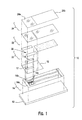
- FIG. 1 is a simplified exploded view of an electrochemical-based analytical test strip 10 according to an embodiment of the present invention.
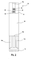
- FIG. 2 is a simplified top view of electrochemical-based analytical test strip 10.
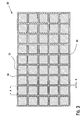
- FIG. 3 is a simplified depiction of a regular square lattice array 30 of electrochemically active and electrochemically inert areas of an electrode as can be employed in embodiments of the present invention.
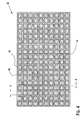
- FIG. 4 is a simplified depiction of another regular square lattice array 40 of electrochemically active and electrochemically inert areas of an electrode as can be employed in embodiments of the present invention.
- electrochemical-based analytical test strip 10 includes an electrically-insulating substrate 12, a patterned conductor layer 14, a patterned insulation layer 16, an enzymatic reagent layer 18, a patterned adhesive layer 20, a hydrophilic layer 22, and a top layer 24.
- patterned conductor layer 14 including reference electrode 14a, first working electrode 14b and second working electrode 14c
- patterned insulation layer 16 with electrode exposure window 17 extending therethrough
- enzymatic reagent layer 18 patterned adhesive layer 20, hydrophilic layer 22 and top layer 24 of electrochemical-based analytical test strip 10 are such that sample receiving-chamber 25 is formed within electrochemical-based analytical test strip 10.
- patterned conductor layer 14 includes a counter electrode 14a (also referred to as a reference electrode), a first working electrode 14b, and a second working electrode 14c.
- electrochemical-based analytical test strip 10 is depicted as including three electrodes, embodiments of electrochemical-based analytical test strips, including embodiments of the present invention, can include any suitable number of electrodes.
- Counter electrode 14a, first working electrode 14b and second working electrode 14c can be formed of any suitable material including, for example, gold, palladium, platinum, indium, titanium-palladium alloys and electrically conducting carbon-based materials.
- the formation of metal electrodes (for example gold electrodes) by conventional methods typically results in a metal electrode with a smooth, uniform and essentially entirely electrochemically active surface area.
- at least one of the electrodes for example, the first and second working electrodes 14b and 14c
- has electrochemically inert areas 26 and electrochemically active areas 28 see FIG.
- electrochemically inert areas are, for simplicity, depicted as open squares and the electrochemically active area(s) as solid lines).
- the electrochemically inert areas and electrochemically active areas are of a predetermined size and a predetermined distribution such that the electrochemical response of the electrode during use of the electrochemical-based analytical test strip is essentially equivalent to a predetermined electrochemical response. Details of such electrochemically active and electrochemically inert areas are described further below with respect to FIGs. 3 and 4 .
- Such electrochemically inert and electrochemically active areas can be configured as a regular array including, for example, a regular square lattice array, regular rectangular array, regular triangular array, regular array of circular electrochemically inert areas, or regular array of polygons. Examples of regular square lattice arrays are depicted in FIGs. 3 and 4 .
- Regular square lattice array 30 of FIG. 3 includes forty-five (45) electrochemically inert areas 32 and an electrically continuous electrochemically active area 34.
- Electrochemically inert areas 32 are configured as electrically isolated squares of 128 ⁇ m per side (dimension A in FIG. 3 ).
- the electrochemically active area 34 is configured as a lattice with a width of 10 ⁇ m (dimension B in FIG.
- Electrochemically active area 34 is separated from each of the forty-five electrochemically inert areas by non-conductive border regions 36 created, for example, by laser ablation of an as deposited gold layer. Therefore, in the embodiment of FIG. 3 , there are forty-five (45) non-conductive border regions 36. Electrochemically active area 34 is approximately 6.3% of the total geometric area of regular square lattice array 30.
- Regular square lattice array 40 of FIG. 4 includes two hundred and forty (240) electrochemically inert areas 42 and an electrically continuous electrochemically active area 44. Electrochemically inert areas 42 are configured as electrically isolated squares of 48 ⁇ m per side (dimension C in FIG. 4 ). The electrochemically active area 44 is configured as a lattice with a width of 10 ⁇ m (dimension D in FIG. 4 ). Electrochemically active area 44 is separated from each of the two hundred and forty electrochemically inert areas by a non-conductive border regions 46 created, for example, by laser ablation of an as deposited gold layer. Therefore, in the embodiment of FIG. 3 , there are two hundred and forty (45) non-conductive border regions 46. Electrochemically active area 44 is approximately 17.5% of the total geometric area of regular square lattice array 40.
- the predetermined size and predetermined distribution of the electrochemically active and electrochemically inert areas will depend on the desired predetermined electrochemical response, whether that electrochemical response be a peak current, peak separation, transient response, early transient response, interferent response, noise response, or combination thereof.
- a typical, but non-limiting width of the at least one electrochemically active area is in the range of 3 ⁇ m to 50 ⁇ m while a typical but non-limiting width of the electrochemically inert areas is in the range of 20 ⁇ m to 200 ⁇ m.
- Regular arrays of chemically inert areas can be formed, for example, by physical blockage of the surface of an electrode or by physically electrically isolating areas in a physical manner. Such physical isolation can be accomplished, for example, using conventional laser ablation techniques that are known to one of skill in the art.
- Physical blockage of the surface can be accomplished, for example, by patterned deposition of an electrically insulating material that is insoluble during use of the electrochemical-based analytical test strip. Such a patterned deposition can employ any suitable technique including, for example, an ink jet printing technique
- Electrically-insulating substrate 12 can be any suitable electrically-insulating substrate known to one skilled in the art including, for example, a nylon substrate, polycarbonate substrate, a polyimide substrate, a polyvinyl chloride substrate, a polyethylene substrate, a polypropylene substrate, a glycolated polyester (PETG) substrate, or a polyester substrate.
- the electrically-insulating substrate can have any suitable dimensions including, for example, a width dimension of about 5 mm, a length dimension of about 27 mm and a thickness dimension of about 0.5 mm.
- Electrically-insulating substrate 12 provides structure to the strip for ease of handling and also serves as a base for the application (e.g., printing or deposition) of subsequent layers (e.g., a patterned conductor layer).
- patterned conductor layers employed in analytical test strips according to embodiments of the present invention can take any suitable shape and be formed of any suitable materials including, for example, metal materials and conductive carbon materials.
- Patterned insulation layer 16 can be formed, for example, from a screen printable insulating ink.
- a screen printable insulating ink is commercially available from Ercon of Wareham, Massachusetts U.S.A. under the name "Insulayer.”
- Patterned adhesive layer 20 can be formed, for example, from a screen-printable pressure sensitive adhesive commercially available from Apollo Adhesives, Tamworth, Staffordshire, UK. In the embodiment of FIGs. 1-4 , patterned adhesive layer 20 defines outer walls of the sample-receiving chamber 26.
- Hydrophilic layer 22 can be, for example, a clear film with hydrophilic properties that promote wetting and filling of electrochemical-based analytical test strip 10 by a fluid sample (e.g., a whole blood sample).
- a fluid sample e.g., a whole blood sample.
- clear films are commercially available from, for example, 3M of Minneapolis, Minnesota U.S.A.
- Enzymatic reagent layer 18 can include any suitable enzymatic reagents, with the selection of enzymatic reagents being dependent on the analyte to be determined. For example, if glucose is to be determined in a blood sample, enzymatic reagent layer 18 can include oxidase or glucose dehydrogenase along with other components necessary for functional operation. Enzymatic reagent layer 18 can include, for example, glucose oxidase, tri-sodium citrate, citric acid, polyvinyl alcohol, hydroxyl ethyl cellulose, potassium ferricyanide, antifoam, cabosil, PVPVA, and water. Further details regarding enzymatic reagent layers, and electrochemical-based analytical test strips in general, are in U.S. Patent No. 6,241,862 , the contents of which are hereby fully incorporated by reference.
- Top layer 24 includes a first portion 24a (e.g. a transparent or translucent first portion) and an opaque second portion 24b.
- First portion 24a and the opaque second portion 24b of the top layer are configured and aligned with the remainder of the analytical test strip such that a user can view the sample-receiving chamber through the first portion of the top layer.
- Top layer 24 can be, for example, a clear film, with opaque second portion 24b being created, for example, by overprinting of the clear film with an opaque ink and first portion 24a being simply clear film without overprinting.
- a suitable clear film is commercially available from Tape Specialities, Tring, Hertfordshire, UK.
- Electrochemical-based analytical test strip 10 can be manufactured, for example, by the sequential aligned formation of patterned conductor layer 14, patterned insulation layer 16 (with electrode exposure window 17 extending therethrough), enzymatic reagent layer 18, patterned adhesive layer 20, hydrophilic layer 22 and top layer 24 onto electrically-insulating substrate 12. Any suitable techniques known to one skilled in the art can be used to accomplish such sequential aligned formation, including, for example, screen printing, photolithography, photogravure, chemical vapour deposition, sputtering, tape lamination techniques and combinations thereof.
- Electrodes 14a, 14b and 14c of patterned conductor layer 14 are employed by, for example, an associated meter to monitor an electrochemical response of the electrochemical-based analytical test strip, for example an electrochemical reaction induced current of interest. The magnitude of such a current can then be correlated with the amount of analyte present in the fluid sample under investigation.
- a bodily fluid sample is introduced into sample-receiving chamber 25 of electrochemical-based analytical test strip 10.
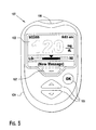
- FIG. 5 is a simplified depiction of a meter 100 for use in combination with electrochemical-based analytical test strips according to embodiments of the present invention (also referred to as an "associated meter").
- FIG. 6 is a simplified top view and block diagram illustrating patterned conductor layer 14 of electrochemical-based analytical test strip 10 interfacing with an associated meter 100.
- Meter 100 includes a display 102, a housing 104, a plurality of user interface buttons 106, an optional soft key 107 and a strip port connector 108.
- Meter 100 further includes electronic circuitry within housing 104 such as a memory 110, a microprocessor 112, electronic components 114 and 116 for applying a test voltage, and also for measuring a plurality of test current values.
- Electrochemical-based analytical test strip 10 is configured for operative insertion into strip port connector 108.
- Memory 110 of meter 100 includes a suitable algorithm that determines an analyte based on the electrochemical response of electrochemical-based analytical test strip 10. The algorithm, therefore, accommodates the electrochemical response of the electrodes within electrochemical-based analytical test strip 10.
- Meter 100 also includes a reference electrode connector 118, a first working electrode connector 120 and a second working electrode connector 122.
- the three aforementioned connectors are part of strip port connector 108.
- a first test voltage source 114 may apply a plurality of test voltages V i between first working electrode 14b and reference electrode 14a, wherein i ranges from 1 to n and more typically 1 to 5.
- meter 100 may then measure a plurality of test currents I i .
- second test voltage source 116 may apply a test voltage V E between second working electrode 14c and reference electrode 14a.
- test voltage V E may then measure a test current I E .
- Test voltages V i and V E may be applied to first and second working electrodes, respectively, either sequentially or simultaneously.
- the working electrode to which V i and V E are applied may be switched, i.e., that V i may be applied to second working electrode and V E may be applied to first working electrode.
- the selection of predetermined size and predetermined distribution for the electrochemically inert areas and at least one electrochemically active area of electrode(s) employed in electrochemical-based analytical test strips according to the present invention can be based on the use of voltammetric sizing to estimate surface blockage (i.e., the size of electrochemically inert areas).
- the peak current and peak separation are as predicted by conventional theory.
- the peak current is directly proportional to the electrode geometric area and the peak separation is as predicted by conventional theory.
- the peak separation is as predicted by conventional theory.
- the peak current is lower than theory and the peak separation is greater than theory.
- the peak current is as predicted by theory and the peak separation is greater than theory.
- FIG. 7 is a graph depicting an example of the dependence of peak current on diffusion layer thickness for reduction of ruthenium hexamine chloride in 1 M KCI at untreated (i.e., no plasma treatment) and plasma-treated screen printed carbon electrodes in comparison to a theoretically predicted peak current.
- FIG. 8 is a graph depicting an example of the dependence of peak separation on diffusion layer thickness for reduction of ruthenium hexamine chloride in 1M KCI at untreated (i.e., no plasma treatment) and plasma-treated screen printed carbon electrodes.
- FIG. 8 is a graph depicting an example of the dependence of peak separation on diffusion layer thickness for reduction of ruthenium hexamine chloride in 1M KCI at untreated (i.e., no plasma treatment) and plasma-treated screen printed carbon electrodes.
- FIG. 9 is a graph depicting experimental results of a voltammetric sizing analysis of screen printed carbon, a simulated gold electrode, and a gold electrode (approximately 35 nm in thickness and produced via sputtering) with a 128 micron regular lattice of electrochemically active and electrochemically inert areas (see FIG. 3 ) created via laser ablation of a deposited gold electrode.
- FIG. 7 indicates that screen printed carbon electrodes (without plasma treatment) deviate from the predicted peak current at a diffusion layer thickness of around 75 ⁇ m.
- FIG. 8 indicates that the peak separation of the plasma treated and non-plasma treated electrodes deviate from one another at diffusion layer thicknesses of less that approximately 75 ⁇ m.
- FIG. 9 depicts the results of the voltammetric sizing and indicates that the peak reduction current of the gold electrode with predetermined electrochemically active and predetermined electrochemically inert areas does indeed provide an electrochemical response essentially equivalent to the predetermined response (i.e., the response of a screen printed carbon electrode).
- FIG. 9 also indicates that a conventional gold electrode would not provide an electrochemical response that was equivalent to that of a screen printed carbon electrode.
- an electrochemical-based analytical test strip and associated meter for the determination of an analyte (e.g., glucose) in a bodily fluid sample includes an electrochemical-based analytical test strip (such as electrochemical-based analytical test strip 10 described above) having an electrically insulating base layer and a patterned conductor layer (for example, a gold patterned conductor layer) disposed over the electrically-insulating layer.
- the patterned conductor layer includes at least one electrode with the electrode having electrochemically inert areas and at least one electrochemically active area.
- the electrochemically inert areas and electrochemically active area(s) are of a predetermined size and a predetermined distribution such that the electrochemical response of the electrode during use of the electrochemical-based analytical test strip is essentially equivalent to a predetermined electrochemical response.
- a meter for example, meter 100 described above and depicted in FIGs. 5 and 6 ) with an algorithm, the meter and algorithm being configured to determine an analyte in a bodily fluid sample applied to the electrochemical-based analytical test strip based on the electrochemical response of the electrode.
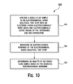
- a method 900 for determining an analyte (such as glucose)in a bodily fluid sample includes applying a bodily fluid sample (for example, a whole blood bodily fluid sample) to an electrochemical-based analytical test strip having an electrically insulating base layer and a patterned conductor layer (for example, a gold patterned conductor layer) disposed over the electrically-insulating layer (see step 910 of FIG. 9 ).
- the patterned conductor layer of step 910 includes at least one electrode with electrochemically inert areas and electrochemically active area(s) (i.e., a heterogeneous electrode).
- the electrochemically inert areas and electrochemically active area(s) are of a predetermined size and a predetermined distribution such that electrochemical response of the electrode during use of the electrochemical-based analytical test strip is essentially equivalent to a predetermined electrochemical response.
- the method includes measuring an electrochemical response of the electrochemical-based analytical test strip and, at step 930, determining the analyte based on the measured electrochemical response.
Landscapes
- Health & Medical Sciences (AREA)
- Life Sciences & Earth Sciences (AREA)
- Chemical & Material Sciences (AREA)
- Immunology (AREA)
- Hematology (AREA)
- Molecular Biology (AREA)
- Physics & Mathematics (AREA)
- Engineering & Computer Science (AREA)
- Pathology (AREA)
- Analytical Chemistry (AREA)
- Biochemistry (AREA)
- General Health & Medical Sciences (AREA)
- General Physics & Mathematics (AREA)
- Biomedical Technology (AREA)
- Electrochemistry (AREA)
- Chemical Kinetics & Catalysis (AREA)
- Biophysics (AREA)
- Urology & Nephrology (AREA)
- Medicinal Chemistry (AREA)
- Food Science & Technology (AREA)
- Biotechnology (AREA)
- Microbiology (AREA)
- Cell Biology (AREA)
- Diabetes (AREA)
- Ecology (AREA)
- Investigating Or Analysing Biological Materials (AREA)
- Measuring Or Testing Involving Enzymes Or Micro-Organisms (AREA)
- Apparatus Associated With Microorganisms And Enzymes (AREA)
Applications Claiming Priority (2)
| Application Number | Priority Date | Filing Date | Title |
|---|---|---|---|
| US12/783,437 US8940141B2 (en) | 2010-05-19 | 2010-05-19 | Analytical test strip with an electrode having electrochemically active and inert areas of a predetermined size and distribution |
| EP11722135.8A EP2572194B1 (fr) | 2010-05-19 | 2011-05-19 | Bande de test analytique comportant une électrode ayant des zones électrochimiquement actives et inertes d'une taille et d'une distribution prédéterminées |
Related Parent Applications (3)
| Application Number | Title | Priority Date | Filing Date |
|---|---|---|---|
| EP11722135.8A Division-Into EP2572194B1 (fr) | 2010-05-19 | 2011-05-19 | Bande de test analytique comportant une électrode ayant des zones électrochimiquement actives et inertes d'une taille et d'une distribution prédéterminées |
| EP11722135.8A Division EP2572194B1 (fr) | 2010-05-19 | 2011-05-19 | Bande de test analytique comportant une électrode ayant des zones électrochimiquement actives et inertes d'une taille et d'une distribution prédéterminées |
| EP11722135.8 Division | 2011-05-19 |
Publications (2)
| Publication Number | Publication Date |
|---|---|
| EP2647992A1 true EP2647992A1 (fr) | 2013-10-09 |
| EP2647992B1 EP2647992B1 (fr) | 2015-10-14 |
Family
ID=44120043
Family Applications (2)
| Application Number | Title | Priority Date | Filing Date |
|---|---|---|---|
| EP13171920.5A Not-in-force EP2647992B1 (fr) | 2010-05-19 | 2011-05-19 | Bande de test analytique avec une électrode ayant des zones inertes et électrochimiquement actives de distribution et taille prédéterminées |
| EP11722135.8A Not-in-force EP2572194B1 (fr) | 2010-05-19 | 2011-05-19 | Bande de test analytique comportant une électrode ayant des zones électrochimiquement actives et inertes d'une taille et d'une distribution prédéterminées |
Family Applications After (1)
| Application Number | Title | Priority Date | Filing Date |
|---|---|---|---|
| EP11722135.8A Not-in-force EP2572194B1 (fr) | 2010-05-19 | 2011-05-19 | Bande de test analytique comportant une électrode ayant des zones électrochimiquement actives et inertes d'une taille et d'une distribution prédéterminées |
Country Status (11)
| Country | Link |
|---|---|
| US (2) | US8940141B2 (fr) |
| EP (2) | EP2647992B1 (fr) |
| JP (1) | JP5988965B2 (fr) |
| KR (1) | KR20130047694A (fr) |
| CN (1) | CN102893150B (fr) |
| AU (1) | AU2011254376B2 (fr) |
| BR (1) | BR112012029450A2 (fr) |
| CA (1) | CA2799657C (fr) |
| ES (2) | ES2558577T3 (fr) |
| RU (1) | RU2012155002A (fr) |
| WO (1) | WO2011144904A1 (fr) |
Families Citing this family (7)
| Publication number | Priority date | Publication date | Assignee | Title |
|---|---|---|---|---|
| CN104380091B (zh) | 2012-06-28 | 2016-06-22 | 西门子医疗保健诊断公司 | 信号放大的读出器设备和方法 |
| GB2518165B (en) * | 2013-09-11 | 2016-04-27 | Cilag Gmbh Int | Electrochemical-based analytical test strip with ultra-thin discontinuous metal layer |
| US9453812B2 (en) * | 2014-06-24 | 2016-09-27 | Lifescan Scotland Limited | End-fill electrochemical-based analytical test strip with perpendicular intersecting sample-receiving chambers |
| US10154809B2 (en) | 2015-06-24 | 2018-12-18 | University Of Virginia Patent Foundation | Test strip device and related methods thereof |
| EP3457121B1 (fr) * | 2017-09-18 | 2025-03-12 | Roche Diabetes Care GmbH | Capteur électrochimique pour détecter au moins un analyte |
| CN112701190B (zh) * | 2020-12-28 | 2022-02-15 | 苏州腾晖光伏技术有限公司 | 一种太阳能电池金属化接触复合电流的测试方法 |
| WO2024096729A1 (fr) * | 2022-11-01 | 2024-05-10 | Universiti Malaya | Appareil de détection de biomarqueurs à partir d'une biomolécule |
Citations (7)
| Publication number | Priority date | Publication date | Assignee | Title |
|---|---|---|---|---|
| US6241862B1 (en) * | 1996-02-14 | 2001-06-05 | Inverness Medical Technology, Inc. | Disposable test strips with integrated reagent/blood separation layer |
| US20040031682A1 (en) * | 2001-11-16 | 2004-02-19 | Wilsey Christopher D. | Method for determining the concentration of an analyte in a liquid sample using small volume samples and fast test times |
| WO2004113910A1 (fr) * | 2003-06-20 | 2004-12-29 | Roche Diagnostics Gmbh | Dispositifs et procedes en relation avec des biocapteurs electrochimiques |
| WO2005045414A1 (fr) * | 2003-10-31 | 2005-05-19 | Lifescan Scotland Limited | Bande d'essai electrochimique reduisant l'effet d'un courant d'interference direct |
| US20060144704A1 (en) * | 2004-12-29 | 2006-07-06 | Ghesquiere Alexander G | Analyte test sensor and method of manufacturing the same |
| US20070227907A1 (en) * | 2006-04-04 | 2007-10-04 | Rajiv Shah | Methods and materials for controlling the electrochemistry of analyte sensors |
| US20090310743A1 (en) * | 2006-04-11 | 2009-12-17 | Carpenter Scott E | Test-Sensor Production Monitoring Using XRF Spectrometry |
Family Cites Families (20)
| Publication number | Priority date | Publication date | Assignee | Title |
|---|---|---|---|---|
| JP2616117B2 (ja) * | 1990-03-23 | 1997-06-04 | 日本電気株式会社 | 修飾電極用平板金属電極 |
| JPH08136575A (ja) * | 1994-11-04 | 1996-05-31 | Murata Mfg Co Ltd | 加速度検出装置 |
| AUPN363995A0 (en) | 1995-06-19 | 1995-07-13 | Memtec Limited | Electrochemical cell |
| US5708247A (en) | 1996-02-14 | 1998-01-13 | Selfcare, Inc. | Disposable glucose test strips, and methods and compositions for making same |
| US6110354A (en) | 1996-11-01 | 2000-08-29 | University Of Washington | Microband electrode arrays |
| US7073246B2 (en) | 1999-10-04 | 2006-07-11 | Roche Diagnostics Operations, Inc. | Method of making a biosensor |
| US6662439B1 (en) | 1999-10-04 | 2003-12-16 | Roche Diagnostics Corporation | Laser defined features for patterned laminates and electrodes |
| JP4184572B2 (ja) * | 2000-04-27 | 2008-11-19 | 松下電器産業株式会社 | バイオセンサ |
| GB0005564D0 (en) | 2000-03-08 | 2000-05-03 | Inverness Medical Ltd | Measurjement of substances in liquid |
| EP1281955B1 (fr) | 2001-04-16 | 2013-06-05 | Panasonic Corporation | Biodétecteur |
| US6814844B2 (en) | 2001-08-29 | 2004-11-09 | Roche Diagnostics Corporation | Biosensor with code pattern |
| AU2003259038A1 (en) | 2002-06-19 | 2004-01-06 | Becton, Dickinson And Company | Microfabricated sensor arrays |
| JP2004235495A (ja) * | 2003-01-31 | 2004-08-19 | Toppan Printing Co Ltd | 超短パルスレーザーによる材料加工方法 |
| CN101533007B (zh) | 2003-10-31 | 2013-01-02 | 生命扫描苏格兰有限公司 | 降低电化学测试条中直接干扰电流的影响的方法 |
| US7655119B2 (en) | 2003-10-31 | 2010-02-02 | Lifescan Scotland Limited | Meter for use in an improved method of reducing interferences in an electrochemical sensor using two different applied potentials |
| US20070240986A1 (en) | 2004-11-12 | 2007-10-18 | Diagnoswiss S.A. | Microfluidic Device with Minimized Ohmic Resistance |
| GB0607205D0 (en) | 2006-04-10 | 2006-05-17 | Diagnoswiss Sa | Miniaturised biosensor with optimized anperimetric detection |
| ES2375288T3 (es) | 2006-10-05 | 2012-02-28 | Lifescan Scotland Limited | Procedimiento para determinar concentraciones de analito corregidas con hematocrito. |
| JP2009019935A (ja) * | 2007-07-10 | 2009-01-29 | Arkray Inc | 分析用具の製造方法 |
| US8608937B2 (en) * | 2009-03-30 | 2013-12-17 | Roche Diagnostics Operations, Inc. | Biosensor with predetermined dose response curve and method of manufacturing |
-
2010
- 2010-05-19 US US12/783,437 patent/US8940141B2/en not_active Expired - Fee Related
-
2011
- 2011-05-19 BR BR112012029450A patent/BR112012029450A2/pt not_active IP Right Cessation
- 2011-05-19 CN CN201180024795.4A patent/CN102893150B/zh not_active Expired - Fee Related
- 2011-05-19 KR KR1020127033010A patent/KR20130047694A/ko not_active Ceased
- 2011-05-19 AU AU2011254376A patent/AU2011254376B2/en not_active Ceased
- 2011-05-19 WO PCT/GB2011/000766 patent/WO2011144904A1/fr not_active Ceased
- 2011-05-19 EP EP13171920.5A patent/EP2647992B1/fr not_active Not-in-force
- 2011-05-19 ES ES13171920.5T patent/ES2558577T3/es active Active
- 2011-05-19 CA CA2799657A patent/CA2799657C/fr not_active Expired - Fee Related
- 2011-05-19 RU RU2012155002/15A patent/RU2012155002A/ru not_active Application Discontinuation
- 2011-05-19 ES ES11722135.8T patent/ES2569420T3/es active Active
- 2011-05-19 JP JP2013510672A patent/JP5988965B2/ja not_active Expired - Fee Related
- 2011-05-19 EP EP11722135.8A patent/EP2572194B1/fr not_active Not-in-force
-
2012
- 2012-07-20 US US13/554,378 patent/US8932449B2/en not_active Expired - Fee Related
Patent Citations (7)
| Publication number | Priority date | Publication date | Assignee | Title |
|---|---|---|---|---|
| US6241862B1 (en) * | 1996-02-14 | 2001-06-05 | Inverness Medical Technology, Inc. | Disposable test strips with integrated reagent/blood separation layer |
| US20040031682A1 (en) * | 2001-11-16 | 2004-02-19 | Wilsey Christopher D. | Method for determining the concentration of an analyte in a liquid sample using small volume samples and fast test times |
| WO2004113910A1 (fr) * | 2003-06-20 | 2004-12-29 | Roche Diagnostics Gmbh | Dispositifs et procedes en relation avec des biocapteurs electrochimiques |
| WO2005045414A1 (fr) * | 2003-10-31 | 2005-05-19 | Lifescan Scotland Limited | Bande d'essai electrochimique reduisant l'effet d'un courant d'interference direct |
| US20060144704A1 (en) * | 2004-12-29 | 2006-07-06 | Ghesquiere Alexander G | Analyte test sensor and method of manufacturing the same |
| US20070227907A1 (en) * | 2006-04-04 | 2007-10-04 | Rajiv Shah | Methods and materials for controlling the electrochemistry of analyte sensors |
| US20090310743A1 (en) * | 2006-04-11 | 2009-12-17 | Carpenter Scott E | Test-Sensor Production Monitoring Using XRF Spectrometry |
Non-Patent Citations (3)
| Title |
|---|
| DAMIEN W. M. ARRIGAN: "Nanoelectrodes, nanoelectrode arrays and their applications", THE ANALYST, vol. 129, no. 12, 9 November 2004 (2004-11-09), pages 1157, XP055075473, ISSN: 0003-2654, DOI: 10.1039/b415395m * |
| SCHELLER F ET AL: "Gesetzmassigkeit fur den Diffusionsgrenzstrom an teilweise blockierten Modellelektroden", JOURNAL OF ELECTROANALYTICAL CHEMISTRY AND INTERFACIAL ELECTRO CHEMISTRY, ELSEVIER, AMSTERDAM, NL, vol. 19, no. 3, 1 November 1968 (1968-11-01), pages 187 - 198, XP026731917, ISSN: 0022-0728, [retrieved on 19681101], DOI: 10.1016/S0022-0728(68)80117-2 * |
| TREVOR J DAVIES ET AL: "Voltammetry at spatially heterogeneous electrodes", JOURNAL OF SOLID STATE ELECTROCHEMISTRY ; CURRENT RESEARCH AND DEVELOPMENT IN SCIENCE AND TECHNOLOGY, SPRINGER, BERLIN, DE, vol. 9, no. 12, 1 December 2005 (2005-12-01), pages 797 - 808, XP019352548, ISSN: 1433-0768, DOI: 10.1007/S10008-005-0699-X * |
Also Published As
| Publication number | Publication date |
|---|---|
| HK1182171A1 (zh) | 2013-11-22 |
| KR20130047694A (ko) | 2013-05-08 |
| CA2799657C (fr) | 2020-03-10 |
| JP2013526715A (ja) | 2013-06-24 |
| HK1190191A1 (en) | 2014-06-27 |
| EP2572194B1 (fr) | 2016-01-27 |
| US20120285837A1 (en) | 2012-11-15 |
| CN102893150B (zh) | 2015-03-11 |
| JP5988965B2 (ja) | 2016-09-07 |
| EP2572194A1 (fr) | 2013-03-27 |
| ES2558577T3 (es) | 2016-02-05 |
| US20110284393A1 (en) | 2011-11-24 |
| AU2011254376B2 (en) | 2016-10-13 |
| US8940141B2 (en) | 2015-01-27 |
| WO2011144904A1 (fr) | 2011-11-24 |
| RU2012155002A (ru) | 2014-06-27 |
| CA2799657A1 (fr) | 2011-11-24 |
| BR112012029450A2 (pt) | 2023-12-05 |
| ES2569420T3 (es) | 2016-05-10 |
| EP2647992B1 (fr) | 2015-10-14 |
| AU2011254376A1 (en) | 2013-01-10 |
| CN102893150A (zh) | 2013-01-23 |
| US8932449B2 (en) | 2015-01-13 |
Similar Documents
| Publication | Publication Date | Title |
|---|---|---|
| US8932449B2 (en) | Analytical test strip with an electrode having electrochemically active and inert areas of a predetermined size and distribution | |
| CA2884172A1 (fr) | Bandelette d'essai analytique a base electrochimique avec des electrodes interferentes nues | |
| EP3004857B1 (fr) | Bande de test analytique à base électrochimique avec un revêtement électrochimiquement actif soluble opposé à une électrode nue | |
| EP2864494B1 (fr) | Bandelette analytique électrochimique à chambres réceptrices d'échantillons en intersection | |
| EP2182355B1 (fr) | Bande de test analytique dotée d'une fenêtre de visualisation de l'échantillon à erreur de remplissage minimale | |
| EP2812444B1 (fr) | Bandelette réactive à base électrochimique avec couche de réactif configurée avec vitesse de remplissage | |
| US20110290668A1 (en) | Analytical test strip with crossroads exposed electrode configuration | |
| HK1182171B (en) | Analytical test strip with an electrode having electrochemically active and inert areas of a predetermined size and distribution | |
| HK1190191B (en) | Analytical test strip with an electrode having electrochemically active and inert areas of a predetermined size and distribution | |
| US20160202204A1 (en) | Electrochemical-based analytical test strip with ultra-thin discontinuous metal layer | |
| HK1222904B (en) | Electrochemical-based analytical test strip with a soluble electrochemically-active coating opposite a bare electrode | |
| HK1205199B (en) | Electrochemical-based analytical test strip with fill-speed configured reagent layer | |
| HK1209796B (en) | Electrochemical-based analytical test strip with intersecting sample-receiving chambers | |
| HK1142129B (en) | Analytical test strip with minimal fill-error sample viewing window |
Legal Events
| Date | Code | Title | Description |
|---|---|---|---|
| PUAI | Public reference made under article 153(3) epc to a published international application that has entered the european phase |
Free format text: ORIGINAL CODE: 0009012 |
|
| AC | Divisional application: reference to earlier application |
Ref document number: 2572194 Country of ref document: EP Kind code of ref document: P |
|
| AK | Designated contracting states |
Kind code of ref document: A1 Designated state(s): AL AT BE BG CH CY CZ DE DK EE ES FI FR GB GR HR HU IE IS IT LI LT LU LV MC MK MT NL NO PL PT RO RS SE SI SK SM TR |
|
| 17P | Request for examination filed |
Effective date: 20140407 |
|
| RBV | Designated contracting states (corrected) |
Designated state(s): AL AT BE BG CH CY CZ DE DK EE ES FI FR GB GR HR HU IE IS IT LI LT LU LV MC MK MT NL NO PL PT RO RS SE SI SK SM TR |
|
| REG | Reference to a national code |
Ref country code: HK Ref legal event code: DE Ref document number: 1190191 Country of ref document: HK |
|
| GRAP | Despatch of communication of intention to grant a patent |
Free format text: ORIGINAL CODE: EPIDOSNIGR1 |
|
| INTG | Intention to grant announced |
Effective date: 20150618 |
|
| GRAS | Grant fee paid |
Free format text: ORIGINAL CODE: EPIDOSNIGR3 |
|
| GRAA | (expected) grant |
Free format text: ORIGINAL CODE: 0009210 |
|
| AC | Divisional application: reference to earlier application |
Ref document number: 2572194 Country of ref document: EP Kind code of ref document: P |
|
| AK | Designated contracting states |
Kind code of ref document: B1 Designated state(s): AL AT BE BG CH CY CZ DE DK EE ES FI FR GB GR HR HU IE IS IT LI LT LU LV MC MK MT NL NO PL PT RO RS SE SI SK SM TR |
|
| REG | Reference to a national code |
Ref country code: GB Ref legal event code: FG4D |
|
| REG | Reference to a national code |
Ref country code: AT Ref legal event code: REF Ref document number: 755527 Country of ref document: AT Kind code of ref document: T Effective date: 20151015 Ref country code: CH Ref legal event code: NV Representative=s name: E. BLUM AND CO. AG PATENT- UND MARKENANWAELTE , CH Ref country code: CH Ref legal event code: EP |
|
| REG | Reference to a national code |
Ref country code: NL Ref legal event code: MP Effective date: 20151014 |
|
| REG | Reference to a national code |
Ref country code: IE Ref legal event code: FG4D |
|
| REG | Reference to a national code |
Ref country code: DE Ref legal event code: R096 Ref document number: 602011020707 Country of ref document: DE |
|
| REG | Reference to a national code |
Ref country code: ES Ref legal event code: FG2A Ref document number: 2558577 Country of ref document: ES Kind code of ref document: T3 Effective date: 20160205 |
|
| REG | Reference to a national code |
Ref country code: LT Ref legal event code: MG4D |
|
| REG | Reference to a national code |
Ref country code: AT Ref legal event code: MK05 Ref document number: 755527 Country of ref document: AT Kind code of ref document: T Effective date: 20151014 |
|
| REG | Reference to a national code |
Ref country code: FR Ref legal event code: PLFP Year of fee payment: 6 |
|
| PG25 | Lapsed in a contracting state [announced via postgrant information from national office to epo] |
Ref country code: NL Free format text: LAPSE BECAUSE OF FAILURE TO SUBMIT A TRANSLATION OF THE DESCRIPTION OR TO PAY THE FEE WITHIN THE PRESCRIBED TIME-LIMIT Effective date: 20151014 Ref country code: IS Free format text: LAPSE BECAUSE OF FAILURE TO SUBMIT A TRANSLATION OF THE DESCRIPTION OR TO PAY THE FEE WITHIN THE PRESCRIBED TIME-LIMIT Effective date: 20160214 Ref country code: NO Free format text: LAPSE BECAUSE OF FAILURE TO SUBMIT A TRANSLATION OF THE DESCRIPTION OR TO PAY THE FEE WITHIN THE PRESCRIBED TIME-LIMIT Effective date: 20160114 Ref country code: LT Free format text: LAPSE BECAUSE OF FAILURE TO SUBMIT A TRANSLATION OF THE DESCRIPTION OR TO PAY THE FEE WITHIN THE PRESCRIBED TIME-LIMIT Effective date: 20151014 Ref country code: HR Free format text: LAPSE BECAUSE OF FAILURE TO SUBMIT A TRANSLATION OF THE DESCRIPTION OR TO PAY THE FEE WITHIN THE PRESCRIBED TIME-LIMIT Effective date: 20151014 |
|
| PG25 | Lapsed in a contracting state [announced via postgrant information from national office to epo] |
Ref country code: AT Free format text: LAPSE BECAUSE OF FAILURE TO SUBMIT A TRANSLATION OF THE DESCRIPTION OR TO PAY THE FEE WITHIN THE PRESCRIBED TIME-LIMIT Effective date: 20151014 Ref country code: SE Free format text: LAPSE BECAUSE OF FAILURE TO SUBMIT A TRANSLATION OF THE DESCRIPTION OR TO PAY THE FEE WITHIN THE PRESCRIBED TIME-LIMIT Effective date: 20151014 Ref country code: PL Free format text: LAPSE BECAUSE OF FAILURE TO SUBMIT A TRANSLATION OF THE DESCRIPTION OR TO PAY THE FEE WITHIN THE PRESCRIBED TIME-LIMIT Effective date: 20151014 Ref country code: GR Free format text: LAPSE BECAUSE OF FAILURE TO SUBMIT A TRANSLATION OF THE DESCRIPTION OR TO PAY THE FEE WITHIN THE PRESCRIBED TIME-LIMIT Effective date: 20160115 Ref country code: LV Free format text: LAPSE BECAUSE OF FAILURE TO SUBMIT A TRANSLATION OF THE DESCRIPTION OR TO PAY THE FEE WITHIN THE PRESCRIBED TIME-LIMIT Effective date: 20151014 Ref country code: PT Free format text: LAPSE BECAUSE OF FAILURE TO SUBMIT A TRANSLATION OF THE DESCRIPTION OR TO PAY THE FEE WITHIN THE PRESCRIBED TIME-LIMIT Effective date: 20160215 Ref country code: FI Free format text: LAPSE BECAUSE OF FAILURE TO SUBMIT A TRANSLATION OF THE DESCRIPTION OR TO PAY THE FEE WITHIN THE PRESCRIBED TIME-LIMIT Effective date: 20151014 Ref country code: RS Free format text: LAPSE BECAUSE OF FAILURE TO SUBMIT A TRANSLATION OF THE DESCRIPTION OR TO PAY THE FEE WITHIN THE PRESCRIBED TIME-LIMIT Effective date: 20151014 |
|
| REG | Reference to a national code |
Ref country code: DE Ref legal event code: R097 Ref document number: 602011020707 Country of ref document: DE |
|
| PG25 | Lapsed in a contracting state [announced via postgrant information from national office to epo] |
Ref country code: CZ Free format text: LAPSE BECAUSE OF FAILURE TO SUBMIT A TRANSLATION OF THE DESCRIPTION OR TO PAY THE FEE WITHIN THE PRESCRIBED TIME-LIMIT Effective date: 20151014 |
|
| PLBE | No opposition filed within time limit |
Free format text: ORIGINAL CODE: 0009261 |
|
| STAA | Information on the status of an ep patent application or granted ep patent |
Free format text: STATUS: NO OPPOSITION FILED WITHIN TIME LIMIT |
|
| PG25 | Lapsed in a contracting state [announced via postgrant information from national office to epo] |
Ref country code: SK Free format text: LAPSE BECAUSE OF FAILURE TO SUBMIT A TRANSLATION OF THE DESCRIPTION OR TO PAY THE FEE WITHIN THE PRESCRIBED TIME-LIMIT Effective date: 20151014 Ref country code: SM Free format text: LAPSE BECAUSE OF FAILURE TO SUBMIT A TRANSLATION OF THE DESCRIPTION OR TO PAY THE FEE WITHIN THE PRESCRIBED TIME-LIMIT Effective date: 20151014 Ref country code: BE Free format text: LAPSE BECAUSE OF NON-PAYMENT OF DUE FEES Effective date: 20160531 Ref country code: DK Free format text: LAPSE BECAUSE OF FAILURE TO SUBMIT A TRANSLATION OF THE DESCRIPTION OR TO PAY THE FEE WITHIN THE PRESCRIBED TIME-LIMIT Effective date: 20151014 Ref country code: EE Free format text: LAPSE BECAUSE OF FAILURE TO SUBMIT A TRANSLATION OF THE DESCRIPTION OR TO PAY THE FEE WITHIN THE PRESCRIBED TIME-LIMIT Effective date: 20151014 Ref country code: RO Free format text: LAPSE BECAUSE OF FAILURE TO SUBMIT A TRANSLATION OF THE DESCRIPTION OR TO PAY THE FEE WITHIN THE PRESCRIBED TIME-LIMIT Effective date: 20151014 |
|
| 26N | No opposition filed |
Effective date: 20160715 |
|
| REG | Reference to a national code |
Ref country code: HK Ref legal event code: GR Ref document number: 1190191 Country of ref document: HK |
|
| PG25 | Lapsed in a contracting state [announced via postgrant information from national office to epo] |
Ref country code: SI Free format text: LAPSE BECAUSE OF FAILURE TO SUBMIT A TRANSLATION OF THE DESCRIPTION OR TO PAY THE FEE WITHIN THE PRESCRIBED TIME-LIMIT Effective date: 20151014 |
|
| PG25 | Lapsed in a contracting state [announced via postgrant information from national office to epo] |
Ref country code: LU Free format text: LAPSE BECAUSE OF FAILURE TO SUBMIT A TRANSLATION OF THE DESCRIPTION OR TO PAY THE FEE WITHIN THE PRESCRIBED TIME-LIMIT Effective date: 20160519 Ref country code: BE Free format text: LAPSE BECAUSE OF FAILURE TO SUBMIT A TRANSLATION OF THE DESCRIPTION OR TO PAY THE FEE WITHIN THE PRESCRIBED TIME-LIMIT Effective date: 20151014 |
|
| REG | Reference to a national code |
Ref country code: FR Ref legal event code: PLFP Year of fee payment: 7 |
|
| REG | Reference to a national code |
Ref country code: FR Ref legal event code: PLFP Year of fee payment: 8 |
|
| PG25 | Lapsed in a contracting state [announced via postgrant information from national office to epo] |
Ref country code: HU Free format text: LAPSE BECAUSE OF FAILURE TO SUBMIT A TRANSLATION OF THE DESCRIPTION OR TO PAY THE FEE WITHIN THE PRESCRIBED TIME-LIMIT; INVALID AB INITIO Effective date: 20110519 Ref country code: CY Free format text: LAPSE BECAUSE OF FAILURE TO SUBMIT A TRANSLATION OF THE DESCRIPTION OR TO PAY THE FEE WITHIN THE PRESCRIBED TIME-LIMIT Effective date: 20151014 |
|
| PG25 | Lapsed in a contracting state [announced via postgrant information from national office to epo] |
Ref country code: MC Free format text: LAPSE BECAUSE OF FAILURE TO SUBMIT A TRANSLATION OF THE DESCRIPTION OR TO PAY THE FEE WITHIN THE PRESCRIBED TIME-LIMIT Effective date: 20151014 Ref country code: MT Free format text: LAPSE BECAUSE OF NON-PAYMENT OF DUE FEES Effective date: 20160531 Ref country code: MK Free format text: LAPSE BECAUSE OF FAILURE TO SUBMIT A TRANSLATION OF THE DESCRIPTION OR TO PAY THE FEE WITHIN THE PRESCRIBED TIME-LIMIT Effective date: 20151014 Ref country code: TR Free format text: LAPSE BECAUSE OF FAILURE TO SUBMIT A TRANSLATION OF THE DESCRIPTION OR TO PAY THE FEE WITHIN THE PRESCRIBED TIME-LIMIT Effective date: 20151014 |
|
| PG25 | Lapsed in a contracting state [announced via postgrant information from national office to epo] |
Ref country code: BG Free format text: LAPSE BECAUSE OF FAILURE TO SUBMIT A TRANSLATION OF THE DESCRIPTION OR TO PAY THE FEE WITHIN THE PRESCRIBED TIME-LIMIT Effective date: 20151014 |
|
| PG25 | Lapsed in a contracting state [announced via postgrant information from national office to epo] |
Ref country code: AL Free format text: LAPSE BECAUSE OF FAILURE TO SUBMIT A TRANSLATION OF THE DESCRIPTION OR TO PAY THE FEE WITHIN THE PRESCRIBED TIME-LIMIT Effective date: 20151014 |
|
| PGFP | Annual fee paid to national office [announced via postgrant information from national office to epo] |
Ref country code: IT Payment date: 20190620 Year of fee payment: 10 Ref country code: ES Payment date: 20190603 Year of fee payment: 9 Ref country code: IE Payment date: 20190509 Year of fee payment: 9 |
|
| PGFP | Annual fee paid to national office [announced via postgrant information from national office to epo] |
Ref country code: CH Payment date: 20190516 Year of fee payment: 9 |
|
| PGFP | Annual fee paid to national office [announced via postgrant information from national office to epo] |
Ref country code: GB Payment date: 20190515 Year of fee payment: 9 |
|
| PG25 | Lapsed in a contracting state [announced via postgrant information from national office to epo] |
Ref country code: LI Free format text: LAPSE BECAUSE OF NON-PAYMENT OF DUE FEES Effective date: 20200531 Ref country code: CH Free format text: LAPSE BECAUSE OF NON-PAYMENT OF DUE FEES Effective date: 20200531 |
|
| GBPC | Gb: european patent ceased through non-payment of renewal fee |
Effective date: 20200519 |
|
| PG25 | Lapsed in a contracting state [announced via postgrant information from national office to epo] |
Ref country code: IE Free format text: LAPSE BECAUSE OF NON-PAYMENT OF DUE FEES Effective date: 20200519 Ref country code: GB Free format text: LAPSE BECAUSE OF NON-PAYMENT OF DUE FEES Effective date: 20200519 |
|
| PGFP | Annual fee paid to national office [announced via postgrant information from national office to epo] |
Ref country code: DE Payment date: 20210420 Year of fee payment: 11 Ref country code: FR Payment date: 20210412 Year of fee payment: 11 |
|
| PG25 | Lapsed in a contracting state [announced via postgrant information from national office to epo] |
Ref country code: IT Free format text: LAPSE BECAUSE OF NON-PAYMENT OF DUE FEES Effective date: 20200519 |
|
| PG25 | Lapsed in a contracting state [announced via postgrant information from national office to epo] |
Ref country code: ES Free format text: LAPSE BECAUSE OF NON-PAYMENT OF DUE FEES Effective date: 20200520 |
|
| REG | Reference to a national code |
Ref country code: DE Ref legal event code: R119 Ref document number: 602011020707 Country of ref document: DE |
|
| PG25 | Lapsed in a contracting state [announced via postgrant information from national office to epo] |
Ref country code: FR Free format text: LAPSE BECAUSE OF NON-PAYMENT OF DUE FEES Effective date: 20220531 |
|
| PG25 | Lapsed in a contracting state [announced via postgrant information from national office to epo] |
Ref country code: DE Free format text: LAPSE BECAUSE OF NON-PAYMENT OF DUE FEES Effective date: 20221201 |