EP2648070A2 - Magnetstreifenlesegerät - Google Patents
Magnetstreifenlesegerät Download PDFInfo
- Publication number
- EP2648070A2 EP2648070A2 EP20130161275 EP13161275A EP2648070A2 EP 2648070 A2 EP2648070 A2 EP 2648070A2 EP 20130161275 EP20130161275 EP 20130161275 EP 13161275 A EP13161275 A EP 13161275A EP 2648070 A2 EP2648070 A2 EP 2648070A2
- Authority
- EP
- European Patent Office
- Prior art keywords
- power
- magnetic stripe
- microprocessor
- decoder
- magnetic
- Prior art date
- Legal status (The legal status is an assumption and is not a legal conclusion. Google has not performed a legal analysis and makes no representation as to the accuracy of the status listed.)
- Withdrawn
Links
Images
Classifications
-
- G—PHYSICS
- G06—COMPUTING OR CALCULATING; COUNTING
- G06K—GRAPHICAL DATA READING; PRESENTATION OF DATA; RECORD CARRIERS; HANDLING RECORD CARRIERS
- G06K7/00—Methods or arrangements for sensing record carriers, e.g. for reading patterns
- G06K7/08—Methods or arrangements for sensing record carriers, e.g. for reading patterns by means detecting the change of an electrostatic or magnetic field, e.g. by detecting change of capacitance between electrodes
- G06K7/082—Methods or arrangements for sensing record carriers, e.g. for reading patterns by means detecting the change of an electrostatic or magnetic field, e.g. by detecting change of capacitance between electrodes using inductive or magnetic sensors
-
- G—PHYSICS
- G06—COMPUTING OR CALCULATING; COUNTING
- G06F—ELECTRIC DIGITAL DATA PROCESSING
- G06F1/00—Details not covered by groups G06F3/00 - G06F13/00 and G06F21/00
- G06F1/26—Power supply means, e.g. regulation thereof
- G06F1/32—Means for saving power
- G06F1/3203—Power management, i.e. event-based initiation of a power-saving mode
- G06F1/3234—Power saving characterised by the action undertaken
-
- G—PHYSICS
- G06—COMPUTING OR CALCULATING; COUNTING
- G06F—ELECTRIC DIGITAL DATA PROCESSING
- G06F1/00—Details not covered by groups G06F3/00 - G06F13/00 and G06F21/00
- G06F1/26—Power supply means, e.g. regulation thereof
- G06F1/32—Means for saving power
- G06F1/3203—Power management, i.e. event-based initiation of a power-saving mode
- G06F1/3206—Monitoring of events, devices or parameters that trigger a change in power modality
-
- G—PHYSICS
- G06—COMPUTING OR CALCULATING; COUNTING
- G06F—ELECTRIC DIGITAL DATA PROCESSING
- G06F1/00—Details not covered by groups G06F3/00 - G06F13/00 and G06F21/00
- G06F1/26—Power supply means, e.g. regulation thereof
- G06F1/32—Means for saving power
- G06F1/3203—Power management, i.e. event-based initiation of a power-saving mode
- G06F1/3234—Power saving characterised by the action undertaken
- G06F1/3287—Power saving characterised by the action undertaken by switching off individual functional units in the computer system
-
- Y—GENERAL TAGGING OF NEW TECHNOLOGICAL DEVELOPMENTS; GENERAL TAGGING OF CROSS-SECTIONAL TECHNOLOGIES SPANNING OVER SEVERAL SECTIONS OF THE IPC; TECHNICAL SUBJECTS COVERED BY FORMER USPC CROSS-REFERENCE ART COLLECTIONS [XRACs] AND DIGESTS
- Y02—TECHNOLOGIES OR APPLICATIONS FOR MITIGATION OR ADAPTATION AGAINST CLIMATE CHANGE
- Y02D—CLIMATE CHANGE MITIGATION TECHNOLOGIES IN INFORMATION AND COMMUNICATION TECHNOLOGIES [ICT], I.E. INFORMATION AND COMMUNICATION TECHNOLOGIES AIMING AT THE REDUCTION OF THEIR OWN ENERGY USE
- Y02D10/00—Energy efficient computing, e.g. low power processors, power management or thermal management
-
- Y—GENERAL TAGGING OF NEW TECHNOLOGICAL DEVELOPMENTS; GENERAL TAGGING OF CROSS-SECTIONAL TECHNOLOGIES SPANNING OVER SEVERAL SECTIONS OF THE IPC; TECHNICAL SUBJECTS COVERED BY FORMER USPC CROSS-REFERENCE ART COLLECTIONS [XRACs] AND DIGESTS
- Y02—TECHNOLOGIES OR APPLICATIONS FOR MITIGATION OR ADAPTATION AGAINST CLIMATE CHANGE
- Y02D—CLIMATE CHANGE MITIGATION TECHNOLOGIES IN INFORMATION AND COMMUNICATION TECHNOLOGIES [ICT], I.E. INFORMATION AND COMMUNICATION TECHNOLOGIES AIMING AT THE REDUCTION OF THEIR OWN ENERGY USE
- Y02D30/00—Reducing energy consumption in communication networks
- Y02D30/50—Reducing energy consumption in communication networks in wire-line communication networks, e.g. low power modes or reduced link rate
Definitions
- the present invention relates to magnetic stripe readers generally.
- the present invention seeks to provide an improved magnetic stripe reader.
- a magnetic stripe reader including a magnetic reader head providing at least one data output, an F2F decoder receiving the at least one data output and providing a decoded data output, a microprocessor receiving and processing the decoded data output and power saving circuitry operative to control the operation of the F2F decoder and the microprocessor thereby to maintain the F2F decoder and the microprocessor in a power-saving sleep mode other than during magnetic stripe reading by the magnetic reader head and a selected time duration thereafter.
- the power saving circuitry receives an output from the magnetic reader head and is responsive to the output for awakening at least the F2F decoder from the power-saving sleep mode.
- the power saving circuitry receives an output from the magnetic reader head and is responsive to the output for awakening the microprocessor from the power-saving sleep mode.
- the magnetic stripe reader also includes a battery supplying power to at least one of the F2F decoder and the microprocessor. Additionally or alternatively, the magnetic stripe reader also includes a circuit controlling flow of the power to the at least one of the F2F decoder and the microprocessor.
- the magnetic stripe reader also includes power saving circuitry connected to at least one of the magnetic reader head, the microprocessor and the F2F decoder. Additionally, the power saving circuitry is operative to awaken the processor and the F2F decoder from the power-saving sleep mode in response to receipt of card swipe activity by the magnetic reader head.
- the at least one power saving module is connected to at least one contact pair of the magnetic reader head. Additionally or alternatively, the power saving circuitry includes at least one power saving module.
- the at least one power saving module includes a capacitor, a resistor and a micro power amplifier, the capacitor being connected, in series with the resistor, to an input of the micro power amplifier.
- the at least one power saving module also includes a comparator, and the comparator includes a first input supplied from an output of the micro power amplifier, a second input coupled to a voltage divider and a third input, receiving an input EN signal from an EN output of the microprocessor. Additionally, an output of the comparator is supplied to an INT input of the microprocessor.
- the voltage divider includes three series connected resistors.
- the microprocessor is operative to supply power to the power saving circuitry when the F2F decoder enters the power-saving sleep mode. Additionally or alternatively, the microprocessor is operative to terminate supplying power to the power saving circuitry when the F2F decoder wakes up from the power-saving sleep mode.
- the microprocessor enters the power-saving sleep mode upon being initialized. Additionally or alternatively, the F2F decoder enters the power-saving sleep mode upon being initialized.
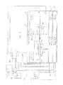
- FIG. 1 is a simplified block diagram/schematic illustration of a magnetic stripe reader constructed and operative in accordance with a preferred embodiment of the present invention.
- a magnetic stripe reader 100 which includes a magnetic reader head 102, typically a three-stripe reader head, commercially available from MTI Electronics Corporation, 1-3 East 4th Street, Kaohsiung Export Processing Zone, Kaohsiung, Taiwan ROC.
- Outputs of the magnetic reader head 102 are typically provided to an F2F decoder 104, such as an IC-MSR MRD532, manufactured by Uniform Industrial Corp of 1F, No 1, Ln 15, Ziqiang Tucheng Dist, New Taipei City 226, Taiwan R.O.C.
- the F2F decoder 104 typically includes a data input from magnetic reader head 102 and is operative to enter a sleep mode when no data signal from a magnetic stripe card is being received by the magnetic reader head 102 and thus the state of the data input remains low for at least a predetermined duration of time.
- An output of the F2F decoder 104 is preferably supplied to a microprocessor 106, such as an IC-MPU STM32L151C6T6 manufactured by STMicroelectronics of 39, Chemin du Champ des Filles Plan-Les-Ouates, Geneva, Switzerland.
- the microprocessor 106 typically includes an INT input which is operative to awaken the microprocessor 106 from a sleep mode upon receipt of an INT signal.
- Both the microprocessor 106 and the F2F decoder 104 typically receive electrical power from a battery 108, such as a coin cell battery, via a switch 110.
- Switch 110 is typically operated by a power-on circuit 112, such as a transistor MMBT3904WT1G manufactured by ON Semiconductor of 5005 East McDowell Road, Phoenix, AZ 85008 USA.
- power saving circuitry 114 is provided and connected to the magnetic reader head 102, the microprocessor 106 and the F2F decoder 104 for monitoring card swipe activity by the magnetic reader head 102 and for awakening both the microprocessor 106 and the F2F decoder 104 from a power saving sleep mode in response to monitored card swipe activity.
- Microprocessor 106 enters the sleep mode when no INT signal is being received from power saving circuitry 114.
- power saving circuitry 114 comprises up to three identical power saving modules 120, each coupled to a different track reading contact pair 122 of the magnetic reader head 102.
- only one or two power saving modules 120 may be provided and connected to only one or two contact pairs 122 of the magnetic reader head 102.
- multiple contact pairs 122 may be coupled to a single suitably configured power saving module.
- Each pair of contacts 122 provides output signals from reading a single stripe of a magnetically encoded card or other medium as an input to a power saving module 120.
- Each contact of each pair of contacts 122 of the magnetic reader head 102 is preferably coupled via a capacitor 124, connected in series with a resistor 126, to an input 128 of a micro power amplifier 130, such as an S-89110BFM-H4A-TFU IC-OPAMP, manufactured by Seiko Instrument of 8, Nakase 1-chome, Mihama-Ku,Chiba-Shi,Chiba, Japan.
- a micro power amplifier 130 such as an S-89110BFM-H4A-TFU IC-OPAMP, manufactured by Seiko Instrument of 8, Nakase 1-chome, Mihama-Ku,Chiba-Shi,Chiba, Japan.
- micro power amplifier 130 The output of micro power amplifier 130 is supplied to an input of a comparator 132, a second input of which is coupled to a voltage divider 134, which includes three series connected resistors 136, 138 and 140. Comparator 132 also receives an input EN signal from an EN output of the microprocessor 106. An output of comparator 132 is supplied to the INT input of microprocessor 106.
- the EN signal is generated by microcontroller 106 as follows. When the F2F decoder 104 enters sleep mode, the EN signal goes high to supply power to power saving circuitry 114. When power saving circuitry 114 detects any signal from magnetic stripe card, the INT signal output of comparator 132 wakes up the microprocessor 106 and the microcontroller 106 then resets the EN signal to low, which results in an immediate termination of supply of electrical power to the power saving circuitry 114, thereby to further save power.
- the magnetic reader head 102 when a magnetic stripe card is read by the magnetic reader head 102, one or more initial zeros are detected.
- the detection of the initial zeros is operative to cause the power saving circuitry 114 to provide a high output to the INT input of the microprocessor 106, thereby to cause the microprocessor 106 to wake up from the sleep mode and to cause the F2F decoder 104 to also wake up from the sleep mode.
- switch 110 When switch 110 is closed, electrical power is supplied to the various circuit components of the magnetic stripe reader 100 and the F2F decoder 104 and the power saving circuitry 114 are initialized. Typically, the F2F decoder 104 enters a power saving sleep mode of operation as does the microprocessor 106.
- the data read by the magnetic stripe reader 102 is then decoded by F2F decoder 104 and further processed by microprocessor 106.
- F2F decoder 104 In the absence of reading additional data by the magnetic stripe reader 102 for at least a predetermined time duration, typically 1 - 60 seconds, both the microprocessor 106 and the F2F decoder 104 re-enter the power saving sleep mode by setting EN signal to high.
Landscapes
- Engineering & Computer Science (AREA)
- Theoretical Computer Science (AREA)
- General Engineering & Computer Science (AREA)
- Physics & Mathematics (AREA)
- General Physics & Mathematics (AREA)
- Computer Hardware Design (AREA)
- Computing Systems (AREA)
- Artificial Intelligence (AREA)
- Computer Vision & Pattern Recognition (AREA)
- Recording Or Reproducing By Magnetic Means (AREA)
- Digital Magnetic Recording (AREA)
Applications Claiming Priority (1)
| Application Number | Priority Date | Filing Date | Title |
|---|---|---|---|
| US201261618890P | 2012-04-02 | 2012-04-02 |
Publications (2)
| Publication Number | Publication Date |
|---|---|
| EP2648070A2 true EP2648070A2 (de) | 2013-10-09 |
| EP2648070A3 EP2648070A3 (de) | 2015-05-27 |
Family
ID=47997168
Family Applications (1)
| Application Number | Title | Priority Date | Filing Date |
|---|---|---|---|
| EP13161275.6A Withdrawn EP2648070A3 (de) | 2012-04-02 | 2013-03-27 | Magnetstreifenlesegerät |
Country Status (2)
| Country | Link |
|---|---|
| US (1) | US8844818B2 (de) |
| EP (1) | EP2648070A3 (de) |
Families Citing this family (5)
| Publication number | Priority date | Publication date | Assignee | Title |
|---|---|---|---|---|
| US20140158767A1 (en) * | 2012-05-15 | 2014-06-12 | Jonathan E. Ramaci | Data reader |
| US10242357B1 (en) | 2015-06-30 | 2019-03-26 | Square, Inc. | Configuration of a payment object reader |
| US9542678B1 (en) | 2016-03-31 | 2017-01-10 | Square, Inc. | Exclusive bonding of wireless devices |
| US10366383B2 (en) | 2016-03-31 | 2019-07-30 | Square, Inc. | Combined reliable and unreliable data transmission |
| US9864424B1 (en) * | 2016-12-23 | 2018-01-09 | Square, Inc. | Power management of point-of-sale component |
Family Cites Families (13)
| Publication number | Priority date | Publication date | Assignee | Title |
|---|---|---|---|---|
| JPH08321136A (ja) * | 1995-05-24 | 1996-12-03 | Sony Corp | デコーダ及び再生装置 |
| US9016572B2 (en) | 2010-10-13 | 2015-04-28 | Square, Inc. | Systems and methods for financial transaction through miniaturized card with ASIC |
| US20120005039A1 (en) * | 2002-02-05 | 2012-01-05 | Jack Dorsey | Method of conducting financial transactions |
| US8302860B2 (en) | 2010-10-13 | 2012-11-06 | Square, Inc. | Read head device with narrow card reading slot |
| US8235287B2 (en) | 2010-10-13 | 2012-08-07 | Square, Inc. | Read head device with slot configured to reduce torque |
| US7430674B2 (en) | 2002-02-12 | 2008-09-30 | Semtek Innovative Solutions, Inc. | Magnetic stripe reader with power management control for attachment to a PDA device |
| US7543739B2 (en) | 2003-12-17 | 2009-06-09 | Qsecure, Inc. | Automated payment card fraud detection and location |
| US7472829B2 (en) | 2004-12-10 | 2009-01-06 | Qsecure, Inc. | Payment card with internally generated virtual account numbers for its magnetic stripe encoder and user display |
| US7163148B2 (en) * | 2004-03-31 | 2007-01-16 | Silicon Labs Cp, Inc. | Magnetic stripe reader |
| CN102598046A (zh) | 2009-10-13 | 2012-07-18 | 平方股份有限公司 | 通过小型化读卡器进行金融交易的系统和方法 |
| EP2537125B1 (de) | 2010-02-16 | 2022-10-12 | Dynamics Inc. | Systeme und verfahren für antriebsschaltungen für dynamische magnetstreifen-kommunikationsvorrichtungen |
| WO2012051067A1 (en) | 2010-10-13 | 2012-04-19 | Square, Inc. | Read head device with slot configured to reduce torque |
| US8534555B1 (en) * | 2012-05-15 | 2013-09-17 | Cypress Semiconductor Corporation | Reconfiguration of a card reader for wake-on-swipe |
-
2013
- 2013-03-25 US US13/849,867 patent/US8844818B2/en active Active
- 2013-03-27 EP EP13161275.6A patent/EP2648070A3/de not_active Withdrawn
Non-Patent Citations (1)
| Title |
|---|
| None |
Also Published As
| Publication number | Publication date |
|---|---|
| US8844818B2 (en) | 2014-09-30 |
| US20130256414A1 (en) | 2013-10-03 |
| EP2648070A3 (de) | 2015-05-27 |
Similar Documents
| Publication | Publication Date | Title |
|---|---|---|
| US8844818B2 (en) | Magnetic stripe reader | |
| US8534555B1 (en) | Reconfiguration of a card reader for wake-on-swipe | |
| US9081569B2 (en) | Active stylus force sensing mechanism for generating a wakeup interrupt to the controller | |
| CN102150102B (zh) | 具有低功率模式的电路 | |
| US20090289908A1 (en) | Touch detecting device capable of saving electricity | |
| US11016548B2 (en) | Single chip system and reset method for single chip system | |
| CN111679861A (zh) | 电子设备的唤醒装置、方法和计算机设备和存储介质 | |
| CN108729762A (zh) | 电子锁的控制系统、控制方法及智能门锁 | |
| CN104597790B (zh) | 一种串口控制器及基于其的微控制器系统的唤醒方法 | |
| US20140372737A1 (en) | Electronic device and method for automatically waking up operating system of electronic device | |
| US11307635B2 (en) | Field-powered biometric device, and method of controlling a field-powered biometric device | |
| CN104158531A (zh) | 电子装置 | |
| CN106940915B (zh) | 一种具有触摸唤醒功能的高频m1卡智能水表 | |
| US8769326B2 (en) | Computer system and operation method for changing operation state by capacitive button group | |
| CN104914975A (zh) | 电脑节能系统及方法 | |
| KR20150111043A (ko) | 손가락 터치를 감지하는 지문 인식 장치 및 그 동작 방법 | |
| CN104049717B (zh) | 节电控制电路和电子设备 | |
| CN113468093A (zh) | 工业级通用串行总线usb芯片、其唤醒方法及电子设备 | |
| CN102801871B (zh) | 射频智能卡及其控制方法 | |
| US20120260116A1 (en) | External power-saving usb mass storage device and power-saving method thereof | |
| KR100834758B1 (ko) | 컴퓨터 시스템 보안 장치 및 방법 | |
| CN104049549B (zh) | 节电控制电路和电子设备 | |
| CN113920621B (zh) | 一种基于nfc的物联网门禁及其设置方法 | |
| CN108958448A (zh) | 主板上电控制电路 | |
| CN118093034B (zh) | 一种计算机睡眠模式的唤醒方法和装置 |
Legal Events
| Date | Code | Title | Description |
|---|---|---|---|
| PUAI | Public reference made under article 153(3) epc to a published international application that has entered the european phase |
Free format text: ORIGINAL CODE: 0009012 |
|
| AK | Designated contracting states |
Kind code of ref document: A2 Designated state(s): AL AT BE BG CH CY CZ DE DK EE ES FI FR GB GR HR HU IE IS IT LI LT LU LV MC MK MT NL NO PL PT RO RS SE SI SK SM TR |
|
| AX | Request for extension of the european patent |
Extension state: BA ME |
|
| PUAL | Search report despatched |
Free format text: ORIGINAL CODE: 0009013 |
|
| AK | Designated contracting states |
Kind code of ref document: A3 Designated state(s): AL AT BE BG CH CY CZ DE DK EE ES FI FR GB GR HR HU IE IS IT LI LT LU LV MC MK MT NL NO PL PT RO RS SE SI SK SM TR |
|
| AX | Request for extension of the european patent |
Extension state: BA ME |
|
| RIC1 | Information provided on ipc code assigned before grant |
Ipc: G06F 1/32 20060101AFI20150423BHEP Ipc: G06K 7/08 20060101ALI20150423BHEP |
|
| 17P | Request for examination filed |
Effective date: 20151123 |
|
| RBV | Designated contracting states (corrected) |
Designated state(s): AL AT BE BG CH CY CZ DE DK EE ES FI FR GB GR HR HU IE IS IT LI LT LU LV MC MK MT NL NO PL PT RO RS SE SI SK SM TR |
|
| 17Q | First examination report despatched |
Effective date: 20160707 |
|
| RAP1 | Party data changed (applicant data changed or rights of an application transferred) |
Owner name: VERIFONE, INC. |
|
| STAA | Information on the status of an ep patent application or granted ep patent |
Free format text: STATUS: THE APPLICATION IS DEEMED TO BE WITHDRAWN |
|
| 18D | Application deemed to be withdrawn |
Effective date: 20170118 |