EP2648082A2 - Appareil de traitement d'informations comportant une unité de génération d'images et une unité de capture d'images, son programme et procédé de traitement d'informations - Google Patents
Appareil de traitement d'informations comportant une unité de génération d'images et une unité de capture d'images, son programme et procédé de traitement d'informations Download PDFInfo
- Publication number
- EP2648082A2 EP2648082A2 EP13161342.4A EP13161342A EP2648082A2 EP 2648082 A2 EP2648082 A2 EP 2648082A2 EP 13161342 A EP13161342 A EP 13161342A EP 2648082 A2 EP2648082 A2 EP 2648082A2
- Authority
- EP
- European Patent Office
- Prior art keywords
- image
- display
- unit
- information processing
- processing apparatus
- Prior art date
- Legal status (The legal status is an assumption and is not a legal conclusion. Google has not performed a legal analysis and makes no representation as to the accuracy of the status listed.)
- Withdrawn
Links
Images









Classifications
-
- G—PHYSICS
- G06—COMPUTING OR CALCULATING; COUNTING
- G06F—ELECTRIC DIGITAL DATA PROCESSING
- G06F3/00—Input arrangements for transferring data to be processed into a form capable of being handled by the computer; Output arrangements for transferring data from processing unit to output unit, e.g. interface arrangements
- G06F3/01—Input arrangements or combined input and output arrangements for interaction between user and computer
-
- G—PHYSICS
- G06—COMPUTING OR CALCULATING; COUNTING
- G06F—ELECTRIC DIGITAL DATA PROCESSING
- G06F1/00—Details not covered by groups G06F3/00 - G06F13/00 and G06F21/00
- G06F1/16—Constructional details or arrangements
- G06F1/1613—Constructional details or arrangements for portable computers
- G06F1/1633—Constructional details or arrangements of portable computers not specific to the type of enclosures covered by groups G06F1/1615 - G06F1/1626
- G06F1/1662—Details related to the integrated keyboard
- G06F1/1673—Arrangements for projecting a virtual keyboard
-
- G—PHYSICS
- G06—COMPUTING OR CALCULATING; COUNTING
- G06F—ELECTRIC DIGITAL DATA PROCESSING
- G06F3/00—Input arrangements for transferring data to be processed into a form capable of being handled by the computer; Output arrangements for transferring data from processing unit to output unit, e.g. interface arrangements
- G06F3/01—Input arrangements or combined input and output arrangements for interaction between user and computer
- G06F3/03—Arrangements for converting the position or the displacement of a member into a coded form
- G06F3/041—Digitisers, e.g. for touch screens or touch pads, characterised by the transducing means
- G06F3/042—Digitisers, e.g. for touch screens or touch pads, characterised by the transducing means by opto-electronic means
- G06F3/0425—Digitisers, e.g. for touch screens or touch pads, characterised by the transducing means by opto-electronic means using a single imaging device like a video camera for tracking the absolute position of a single or a plurality of objects with respect to an imaged reference surface, e.g. video camera imaging a display or a projection screen, a table or a wall surface, on which a computer generated image is displayed or projected
- G06F3/0426—Digitisers, e.g. for touch screens or touch pads, characterised by the transducing means by opto-electronic means using a single imaging device like a video camera for tracking the absolute position of a single or a plurality of objects with respect to an imaged reference surface, e.g. video camera imaging a display or a projection screen, a table or a wall surface, on which a computer generated image is displayed or projected tracking fingers with respect to a virtual keyboard projected or printed on the surface
-
- G—PHYSICS
- G06—COMPUTING OR CALCULATING; COUNTING
- G06F—ELECTRIC DIGITAL DATA PROCESSING
- G06F3/00—Input arrangements for transferring data to be processed into a form capable of being handled by the computer; Output arrangements for transferring data from processing unit to output unit, e.g. interface arrangements
- G06F3/01—Input arrangements or combined input and output arrangements for interaction between user and computer
- G06F3/048—Interaction techniques based on graphical user interfaces [GUI]
- G06F3/0487—Interaction techniques based on graphical user interfaces [GUI] using specific features provided by the input device, e.g. functions controlled by the rotation of a mouse with dual sensing arrangements, or of the nature of the input device, e.g. tap gestures based on pressure sensed by a digitiser
- G06F3/0488—Interaction techniques based on graphical user interfaces [GUI] using specific features provided by the input device, e.g. functions controlled by the rotation of a mouse with dual sensing arrangements, or of the nature of the input device, e.g. tap gestures based on pressure sensed by a digitiser using a touch-screen or digitiser, e.g. input of commands through traced gestures
- G06F3/04886—Interaction techniques based on graphical user interfaces [GUI] using specific features provided by the input device, e.g. functions controlled by the rotation of a mouse with dual sensing arrangements, or of the nature of the input device, e.g. tap gestures based on pressure sensed by a digitiser using a touch-screen or digitiser, e.g. input of commands through traced gestures by partitioning the display area of the touch-screen or the surface of the digitising tablet into independently controllable areas, e.g. virtual keyboards or menus
-
- H—ELECTRICITY
- H04—ELECTRIC COMMUNICATION TECHNIQUE
- H04N—PICTORIAL COMMUNICATION, e.g. TELEVISION
- H04N23/00—Cameras or camera modules comprising electronic image sensors; Control thereof
- H04N23/60—Control of cameras or camera modules
- H04N23/61—Control of cameras or camera modules based on recognised objects
-
- H—ELECTRICITY
- H04—ELECTRIC COMMUNICATION TECHNIQUE
- H04N—PICTORIAL COMMUNICATION, e.g. TELEVISION
- H04N23/00—Cameras or camera modules comprising electronic image sensors; Control thereof
- H04N23/60—Control of cameras or camera modules
- H04N23/67—Focus control based on electronic image sensor signals
-
- G—PHYSICS
- G03—PHOTOGRAPHY; CINEMATOGRAPHY; ANALOGOUS TECHNIQUES USING WAVES OTHER THAN OPTICAL WAVES; ELECTROGRAPHY; HOLOGRAPHY
- G03B—APPARATUS OR ARRANGEMENTS FOR TAKING PHOTOGRAPHS OR FOR PROJECTING OR VIEWING THEM; APPARATUS OR ARRANGEMENTS EMPLOYING ANALOGOUS TECHNIQUES USING WAVES OTHER THAN OPTICAL WAVES; ACCESSORIES THEREFOR
- G03B13/00—Viewfinders; Focusing aids for cameras; Means for focusing for cameras; Autofocus systems for cameras
- G03B13/18—Focusing aids
- G03B13/30—Focusing aids indicating depth of field
Definitions
- the present disclosure relates to an information processing apparatus, a program, and an information processing method.
- the input apparatus that projects an image of an input apparatus such as a keyboard on a plane of projection and receives, as an operation input, an operation of a user on the plane of projection is being developed.
- the input apparatus is configured to be able to determine an operation of a user, e.g., a motion of a hand by taking an image of a plane of projection with a camera.
- Japanese Patent Application Laid-open No. 2008-123316 discloses a data input method and data input apparatus, which take an image of a plane of projection of a keyboard image by using a plurality of imaging means, analyze the imaging data, specify a position of a user's finger that is in contact with the plane of projection, and receive a motion of the finger as an operation input.
- a data input method and data input apparatus which take an image of a plane of projection of a keyboard image by using a plurality of imaging means, analyze the imaging data, specify a position of a user's finger that is in contact with the plane of projection, and receive a motion of the finger as an operation input.
- an information processing apparatus capable of generating an image that has reflected the configuration of an object within an imaging range based on a taken image, a program, and an information processing method.
- an information processing apparatus includes an imaging unit; and an image generation unit to generate a display image based on a distance between the imaging unit and an object, wherein the distance is detected by using a plurality of images obtained by the imaging unit at respective focus distances.
- the present disclosure relates to an information processing apparatus that projects an image or displays an image on a display, a program, and an information processing method.
- Fig. 1 is a schematic diagram showing a configuration of an information processing apparatus 100 according to the first embodiment of the present disclosure.
- the information processing apparatus 100 includes an imaging unit 101, an image obtaining unit 102, a distance detection unit 103, an image generation unit 104, an image display unit 105, and an input processing unit 106.
- the imaging unit 101 is connected with the image obtaining unit 102, and the image obtaining unit 102 is connected with the distance detection unit 103.
- the distance detection unit 103 is connected with the image generation unit 104, and the image generation unit 104 is connected with the image display unit 105.
- the input processing unit 106 is connected with the distance detection unit 103.
- the information processing apparatus 100 can be any apparatus that is capable of generating and displaying an image, e.g., a cellular phone, a portable information terminal, and various computers such as a personal computer.
- an image (hereinafter referred to as display image) S of an object to be displayed e.g., keyboard
- a plane of projection P e.g., desk
- a user performs an input operation (e.g., typing) on the plane of projection P with reference to the display image S.
- a hand of the user is represented as hand H.
- the imaging unit 101 includes an image sensor such as a CCD (Charge Coupled Device) and a CMOS (Complementary Metal Oxide Semiconductor) and a necessary optical system, and takes an image in an imaging range.
- the imaging unit 101 can change a focus distance (distance between the imaging unit 101 and the focal point), and changes the focus distance (focus) under control of the image obtaining unit 102.
- the imaging unit 101 outputs a taken image (hereinafter referred to as image) to the image obtaining unit 102.
- the image obtaining unit 102 obtains an image taken by the imaging unit 101 and supplies the image to the distance detection unit 103.
- the image obtaining unit 102 controls the imaging unit 101, thereby causing the imaging unit 101 to change the focus distance and take an image.
- the image obtaining unit 102 causes the imaging unit 101 to take an image at a plurality of focus distances.
- the distance detection unit 103 performs predetermined image processing for a plurality of images supplied from the image obtaining unit 102, and detects a distance (hereinafter referred to as object distance) between the imaging unit 101 and an object (here, the user's hand H) within an imaging range of the imaging unit 101.
- the distance detection unit 103 supplies the object distance to the input processing unit 106 and the image generation unit 104.
- the image generation unit 104 performs predetermined image processing for a plurality of images supplied from the image obtaining unit 102, and generates, based on the processing result, the display image S that is displayed by the image display unit 105. Although the details will be described later, the image generation unit 104 generates, based on the object distance, an image mask, and generates the display image S by using the image mask.
- the image display unit 105 is a unit (projector) that can project an image, and projects the display image S that is generated by the image generation unit 104 on the plane of projection P.
- the image display unit 105 may be a projector that uses an arbitrary system. It is desirable that the image display unit 105 is disposed close to the imaging unit 101.
- the input processing unit 106 determines a user's operation input based on the object distance supplied from the distance detection unit 103, and performs input processing for the operation input. Although the details will be described later, the input processing unit 106 detects a contact of the user's hand H on the plane of projection p, and determines the user's operation input based on the positional relationship between the contact position and the display image S. The input processing generated by the input processing unit 106 is supplied to an operating system of the information processing apparatus 100.
- the information processing apparatus 100 has the configuration described above.
- the image obtaining unit 102, the distance detection unit 103, the image generation unit 104, and the input processing unit 106 can be functional parts implemented by the cooperation between software and hardware, are not limited to be housed physically in the casing of the information processing apparatus 100, and may also be mounted on a network.
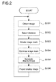
- Fig. 2 is a flowchart showing an operation of the information processing apparatus 100.
- the image obtaining unit 102 obtains an image (St101).
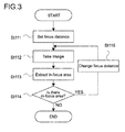
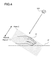
- Fig. 3 is a flowchart showing how to obtain an image by the image obtaining unit 102, and Fig. 4 is a schematic diagram showing a state of obtaining an image.
- the image obtaining unit 102 controls the imaging unit 101 to set the focus distance to an initial value (St111).
- the initial value is a distance in which the plane of projection P is expected to be sufficiently included from the imaging unit 101, and can be set depending on, for example, the position of the imaging unit 101 in the information processing apparatus 100.
- Fig. 4 shows, as a plane A, a plane including a focus distance that has the initial value.
- the image obtaining unit 102 causes the imaging unit 101 to take an image at the focus distance (plane A) (St112).
- the image obtaining unit 102 extracts an in-focus area from the image taken on the plane A (St113).
- the in-focus area is an area in focus in an image, and can be detected based on, for example, a contrast or phase difference of each pixel in the image.
- the image obtaining unit 102 confirms whether or not an in-focus area has been detected in an image (St114).
- the image obtaining unit 102 moves the focus distance (St115). Specifically, the image obtaining unit 102 changes the focus distance from the initial value (plane A) to a distance closer to the imaging unit 101 (plane B).
- the interval between the plane A and the plane B is arbitrary, and can be, for example, several mm if the depth of field is shallow.
- the image obtaining unit 102 repeats a process of changing a focus distance, a process of taking an image, and subsequent processes, as long as an in-focus area is detected. In the case where an in-focus area has not been detected (No in St114), the image obtaining unit 102 ends the process of obtaining an image. For example, an image is taken between the plane A and a plane C at a predetermined interval in the case of Fig. 4 , because a focus distance at which an in-focus area is detected last (hand H exists) is on the plane C.
- the in-focus area can be deleted because an in-focus area on the plane of projection P is almost straight and can be in-focus area data that is obviously different from a solid object such as a hand, if the plane of projection P has a flat surface such as a desk or a curved surface with fewer concavity and convexity than a hand.
- the image obtaining unit 102 obtains a plurality of images taken at a predetermined interval in a range that includes at least the user's hand H. Moreover, the image obtaining unit 102 stores data on an in-focus area, which is used for the detection of the object (hand H).
- the distance detection unit 103 detects the distance (object distance) between the imaging unit 101 and the object (hand H) within an imaging range of the imaging unit 101 (St102). Specifically, the distance detection unit 103 can detect, by specifying the position of the hand H for each image based on a distribution of an in-focus area in the image, the configuration of the object (distance between respective parts of the hand H and the imaging unit 101). The distance detection unit 103 supplies the object distance to the image generation unit 104.
- the image generation unit 104 creates an image mask (St103).
- the image generation unit 104 calculates the shape of the hand H projected on a plane closer to the imaging unit 101 than the plane of projection P (e.g., plane C) by using the object distance detected by the distance detection unit 103 to create an image mask.
- Fig. 5 shows an example of an image mask M created by the image generation unit 104.
- Figs. 6 and 7 are each a schematic diagram showing an optimization of the image mask M by the image generation unit 104.
- the image generation unit 104 magnifies the image mask M at a predetermined proportion (e.g., about 5 to 10%).
- the image mask M is contracted at a predetermined proportion (e.g., about -5 to - 10%) if a shadow on the plane of projection P is annoying, i.e., a mask optimal value can be incremented and decremented sequentially.
- the image generation unit 104 can blur the boundaries of the image mask M.
- Fig. 8 is a schematic diagram showing how to generate the display image S by the image generation unit 104.
- the image generation unit 104 combines the image mask M with an image (hereinafter referred to as display object image) G of an object to be displayed (here, keyboard) to generate the display image S.
- display object image an image of an object to be displayed (here, keyboard)
- the image generation unit 104 supplies the generated display image S to the image display unit 105 and causes the image display unit 105 to project the display image S (St106).
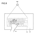
- Fig. 9 is a diagram showing the display image S projected by the image display unit 105. As shown in the figure, the display object image G is not projected on the user's hand H, because the display object image G is not displayed on the image mask M. Therefore, it is possible to prevent the visibility from being deteriorated. At this time, the image generation unit 104 may perform power control to cut power that is necessary for displaying the area corresponding to the image mask M.
- the input processing unit 106 performs input processing for the user's operation input along with the generation and projection of the display image S.
- the input processing unit 106 can determine whether or not the hand H is in contact with the plane of projection P based on the distance (object distance) between the hand H and the imaging unit 101, which is supplied from the distance detection unit 103.
- the input processing unit 106 determines the user's operation input based on, for example, the positional relationship between the display image S and the place at which the hand H is in contact with the plane of projection P.
- the imaging unit 101 it is possible to detect a distance between the imaging unit 101 and the object (hand H) within the imaging range based on a plurality of images taken at a different focus distance. Further, it is possible to generate an image mask by using the distance. Accordingly, the display object image G is prevented from being projected on the hand H, thereby preventing the user's visibility from being deteriorated.
- Fig. 10 is a schematic diagram showing a configuration of an information processing apparatus 200 according to the second embodiment.
- the information processing apparatus 200 includes an imaging unit 201, an image obtaining unit 202, a distance detection unit 203, an image generation unit 204, an image display unit 205, and an input processing unit 206.
- the imaging unit 201 is connected with the image obtaining unit 202, and the image obtaining unit 202 is connected with the distance detection unit 203.
- the distance detection unit 203 is connected with the image generation unit 204, and the image generation unit 204 is connected with the image display unit 205.
- the input processing unit 206 is connected with the distance detection unit 203.
- the information processing apparatus 200 can be any apparatus that is capable of generating and displaying an image, e.g., a cellular phone, a portable information terminal, and various computers such as a personal computer.
- a user performs an input operation (e.g., typing) on an operational plane P (e.g., regular desk) that displays nothing.
- a hand of the user is represented as hand H.
- An image of the operational plane P including the hand H is taken by the imaging unit 201, and an image obtained by combining an image of the hand H and an image of an object to be displayed (e.g., keyboard) is displayed on the image display unit 205 as the display image S.
- the imaging unit 201 includes an image sensor such as a CCD (Charge Coupled Device) and a CMOS (Complementary Metal Oxide Semiconductor) and a necessary optical system, and takes an image in an imaging range.
- the imaging unit 201 can change a focus distance (distance between the imaging unit 201 and the focal point), and changes the focus distance (focus) under control of the image obtaining unit 202.
- the imaging unit 201 outputs a taken image (hereinafter referred to as image) to the image obtaining unit 202.
- the imaging unit 201 is desirably mounted to the image display unit 205 (e.g., display).
- the image obtaining unit 202 obtains an image taken by the imaging unit 201 and supplies the image to the distance detection unit 203.
- the image obtaining unit 202 controls the imaging unit 201, thereby causing the imaging unit 201 to change the focus distance and take an image.
- the image obtaining unit 202 causes the imaging unit 201 to take an image at a plurality of focus distances.
- the distance detection unit 203 performs predetermined image processing for a plurality of images supplied from the image obtaining unit 202, and detects a distance (hereinafter referred to as object distance) between the imaging unit 201 and an object (here, the user's hand H) within an imaging range of the imaging unit 201.
- the distance detection unit 203 supplies the object distance to the input processing unit 206 and the image generation unit 204.
- the image generation unit 204 performs predetermined image processing for a plurality of images supplied from the image obtaining unit 202, and generates, based on the processing result, the display image S that is displayed by the image display unit 205. Although the details will be described later, the image generation unit 204 extracts, based on the object distance, an image of the hand H from the image, and generates the display image S by using the image of the hand H.
- the image display unit 205 is a unit (display) that can display an image, and displays the display image S that is generated by the image generation unit 204 on a display screen.
- the image display unit 205 may be a display that uses an arbitrary system. As described above, to the image display unit 205, the imaging unit 201 is mounted.
- the input processing unit 206 determines a user's operation input based on the object distance supplied from the distance detection unit 203, and performs input processing for the operation input. Although the details will be described later, the input processing unit 206 detects a contact of the user's hand H on the operational plane p, and determines the user's operation input based on the positional relationship between the contact position and the imaging unit 201. The input processing generated by the input processing unit 206 is supplied to an operating system of the information processing apparatus 200.
- the information processing apparatus 200 has the configuration described above.
- the image obtaining unit 202, the distance detection unit 203, the image generation unit 204, and the input processing unit 206 can be functional parts implemented by the cooperation between software and hardware, are not limited to be housed physically in the casing of the information processing apparatus 200, and may also be mounted on a network.
- Fig. 11 is a flowchart showing an operation of the information processing apparatus 200.
- the image obtaining unit 202 obtains an image (St201).
- the image obtaining unit 202 can obtain an image in the same manner as the first embodiment. Specifically, the image obtaining unit 202 obtains a plurality of images taken at a predetermined interval in a range that includes at least the user's hand H while moving a focus distance of the imaging unit 201. Moreover, the image obtaining unit 202 stores data on an in-focus area, which is used for the detection of the object (hand H).
- the distance detection unit 203 detects the distance (object distance) between the imaging unit 201 and the object (hand H) within an imaging range of the imaging unit 201 (St202). Specifically, the distance detection unit 203 can detect, by specifying the position of the hand H for each image based on a distribution of an in-focus area in the image, the configuration of the object (distance between respective parts of the hand H and the imaging unit 201). The distance detection unit 203 supplies the object distance to the image generation unit 204.
- the image generation unit 204 extracts an object image (image of the hand H) by using the object distance (St203). Specifically, the image generation unit 204 selects one image, e.g., an (extensively focused) image that has the largest in-focus area, from a plurality of images obtained by the image obtaining unit 202. The image generation unit 204 can extract an image area (object image) corresponding to the hand H from the image by using the object distance.
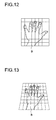
- Fig. 12 is a schematic diagram showing an object image B that is extracted by the image generation unit 204.
- the image generation unit 204 modifies the extracted object image B as necessary (St204).
- Fig. 12 in the object image B, a side of the hand H, which is close to the imaging unit 201, is magnified depending on the positional relationship between the imaging unit 201 and the hand H in some cases.
- Fig. 13 is a schematic diagram showing the modified object image B.
- the image generation unit 204 compresses an area in the object image B, which is close to the imaging unit 201, and extends an area in the object image B, which is distant from the imaging unit 201, as shown in Fig. 13 .
- the image generation unit 204 can modify the object image B. Accordingly, it is possible to prevent the deformation of the object image B due to the difference between the viewpoint of the user and the viewpoint of the imaging unit 201.
- Fig. 14 is a schematic diagram showing the display image S generated by the image generation unit 204.
- the image generation unit 204 superimposes the object image B on the image (hereinafter referred to as display object image) G of an object to be displayed (here, keyboard) to generate the display image S.
- the image generation unit 204 performs alignment of the object image B and the display object image G.
- the image generation unit 204 can set an area in the object image B, which corresponds to a left pinky finger of the hand H, to the vicinity of the "Q" key in the keyboard, and an area in the object image B, which corresponds to a right pinky finger of the hand H, to the vicinity of the "Enter" key in the keyboard. If the alignment is performed frequently, a description of the display object image G blurs. Therefore, the alignment only has to be performed when the display image is generated first.
- the image generation unit 204 can permeabilize the object image B when generating the display image S.
- Fig. 15 is a schematic diagram showing the display image S generated from an object image permeabilized by the image generation unit 204. As shown in the figure, the object image B is permeabilized. Accordingly, the display object image G is displayed through the object image B, and the user can visually confirm the display object image G. Moreover, the image generation unit 204 can dye the object image B with a color instead of the permeabilization to clearly show the object image B (i.e., the hand H) for the user.
- the image generation unit 204 outputs the generated display image S to the image display unit 205, and causes the image display unit 205 to display the display image S on a display screen thereof (St206).
- the user can perform an operation input on the operational plane P that displays nothing, with reference to the display object image G displayed on the image display unit 205.
- the input processing unit 206 performs input processing for the user's operation input along with the generation and display of the display image S.
- the input processing unit 206 can determine whether or not the hand H is in contact with the operational plane P based on the distance (object distance) between respective parts of the hand H and the imaging unit 201, which is supplied from the distance detection unit 203.
- the input processing unit 206 determines the user's operation input based on, for example, the positional relationship between the imaging unit 201 and the place at which the hand H is in contact with the operational plane P.
- the imaging unit 201 it is possible to detect a distance between the imaging unit 201 and the object (hand H) within the imaging range based on a plurality of images taken at a different focus distance. Further, it is possible to extract an image of the object by using the distance. Accordingly, a display image obtained by combining the object and the display object image is displayed. The user can perform input processing with reference to the display image.
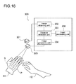
- Fig. 16 is a schematic diagram showing a configuration of an information processing apparatus 300 according to the third embodiment.
- the information processing apparatus 300 includes an imaging unit 301, an image obtaining unit 302, a distance detection unit 303, an image generation unit 304, an image display unit 305, and an input processing unit 306.
- the imaging unit 301 is connected with the image obtaining unit 302, and the image obtaining unit 302 is connected with the distance detection unit 303.
- the distance detection unit 303 is connected with the image generation unit 304, and the image generation unit 304 is connected with the image display unit 305.
- the input processing unit 306 is connected with the distance detection unit 303.
- the information processing apparatus 300 can be any apparatus that is capable of generating and projecting an image, e.g., a cellular phone, a portable information terminal, and various computers such as a personal computer.
- an image (display image S) of an object to be displayed is projected on the plane of projection P that is a surface of a hand H1 of a user.
- the user performs an input operation (e.g., typing) on the plane of projection P with reference to the display image S.
- a hand of the user, which is used for the input operation, is represented as hand H2.
- the imaging unit 301 includes an image sensor such as a CCD (Charge Coupled Device) and a CMOS (Complementary Metal Oxide Semiconductor) and a necessary optical system, and takes an image in an imaging range.
- the imaging unit 301 can change a focus distance (distance between the imaging unit 301 and the focal point), and changes the focus distance (focus) under control of the image obtaining unit 302.
- the imaging unit 301 outputs a taken image (hereinafter referred to as image) to the image obtaining unit 302.
- the imaging unit 301 is not limited to the image sensor described above, and may use a dedicated method for measuring a distance image, such as a TOF (time-of-flight) method.
- a distance to an object is measured based on the arrival time of light.
- non-visible light such as an infrared ray is pulse-modulated to be irradiated within the angle of view, and an image sensor measures the pulse phase lag.
- the image obtaining unit 302 obtains an image taken by the imaging unit 301 and supplies the image to the distance detection unit 303.
- the image obtaining unit 302 controls the imaging unit 301, thereby causing the imaging unit 301 to change the focus distance and take an image.
- the image obtaining unit 302 causes the imaging unit 301 to take an image at a plurality of focus distances.
- the distance detection unit 303 performs predetermined image processing for a plurality of images supplied from the image obtaining unit 302, and detects a distance (hereinafter referred to as object distance) between the imaging unit 301 and an object (here, the user's hand H1) within an imaging range of the imaging unit 301.
- the distance detection unit 303 supplies the object distance to the input processing unit 306 and the image generation unit 304.
- the image generation unit 304 performs predetermined image processing for a plurality of images supplied from the image obtaining unit 302, and generates, based on the processing result, the display image S that is projected by the image display unit 305. Although the details will be described later, the image generation unit 304 detects, based on the object distance, a concavity and convexity of the plane of projection P and generates an image corrected based on the concavity and convexity as the display image S.
- the image display unit 305 is a unit (projector) that can project an image, and projects the display image S that is generated by the image generation unit 304 on the plane of projection P.
- the image display unit 305 may be a projector that uses an arbitrary system. It is desirable that the image display unit 305 is disposed close to the imaging unit 301.
- the input processing unit 306 determines a user's operation input based on the object distance supplied from the distance detection unit 303, and performs input processing for the operation input. Although the details will be described later, the input processing unit 306 detects a contact of the user's hand H2 on the plane of projection p, and determines the user's operation input based on the positional relationship between the contact position and the imaging unit 301. The input processing generated by the input processing unit 306 is supplied to an operating system of the information processing apparatus 300.
- the information processing apparatus 300 has the configuration described above.
- the image obtaining unit 302, the distance detection unit 303, the image generation unit 304, and the input processing unit 306 can be functional parts implemented by the cooperation between software and hardware, are not limited to be housed physically in the casing of the information processing apparatus 300, and may also be mounted on a network.
- Fig. 17 is a flowchart showing an operation of the information processing apparatus 300.
- the image obtaining unit 302 obtains an image (St301).
- the image obtaining unit 302 can obtain an image in the same manner as the first embodiment. Specifically, the image obtaining unit 302 obtains a plurality of images taken at a predetermined interval in a range that includes at least the user's hand H1 while moving a focus distance of the imaging unit 301. Moreover, the image obtaining unit 302 stores data on an in-focus area, which is used for the detection of the object (hand H1).
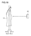
- Fig. 18 is a schematic diagram showing planes including a focus distance at which an image is taken. The image is taken on a plane A, plane B, plane C, and plane D of the hand H1 shown in Fig. 18 .
- Figs. 19A to 19D are each a schematic diagram showing an in-focus area in each image.
- Fig. 19A shows an in-focus area R in an image taken on the plane A shown in Fig. 18 .
- Figs. 19B, 19C, and 19D show the in-focus area R in an image taken on the planes B, C, and D shown in Fig. 18 , respectively.
- a distribution of an in-focus area in each image is different because a distance between the hand H1 and the imaging unit 301 is different depending on the concavity and convexity of the hand H1 (plane of projection P).
- the distance detection unit 303 detects the distance between the imaging unit 301 and the object (hand H1) within the imaging range of the imaging unit 301 (St302). Specifically, the distance detection unit 303 can detect the concavity and convexity of the plane of projection P (distance between the imaging unit 301 and respective parts of the hand H1) by specifying the position of the hand H1 for each image based on the distribution of the in-focus area R in each image. The distance detection unit 303 supplies the object distance to the image generation unit 304.
- the image generation unit 304 corrects the image (hereinafter referred to as display object image) G of an object to be displayed by using the object distance (St303).
- Figs. 20A and 20B are each a schematic diagram showing an example of how to correct the display object image G. As shown in Fig. 20B , the image generation unit 304 corrects the display object image G shown in Fig. 20A in accordance with the concavity and convexity of the plane of projection P, which is detected by the distance detection unit 303.
- the image generation unit 304 can correct the display object image G so as to compress an area of the display object image G projected on an area (convex area) on the plane of projection P, which is close to the imaging unit 301, and extend an area of the display object image G projected on an area (concave area) on the plane of projection P, which is distant from the imaging unit 301.
- the image generation unit 304 generates the display image S by using the display object image G corrected as describe above (St304).
- the image generation unit 304 outputs the generated display image S to the image display unit 305, and causes the image display unit 305 to project the display image S on the plane of projection P (St305).
- Fig. 21 is a schematic diagram showing the display image S projected on the plane of projection P. As shown in the figure, since the display image S is corrected depending on the concavity and convexity of the plane of projection P, it causes no distortion of an image due to the concavity and convexity of the plane of projection P.
- the input processing unit 306 performs input processing for the user's operation input along with the generation and projection of the display image S.
- the input processing unit 306 can determine whether or not the hand H2 is in contact with the plane of projection P based on the distance (object distance) between respective parts of the hand H2 and the imaging unit 301, which is supplied from the distance detection unit 303.
- the input processing unit 206 can determine the user's operation input based on, for example, the positional relationship between the imaging unit 301 and the place at which the hand H2 is in contact with the plane of projection P.
- the detected object distance is used for generating the display object image G, but is not limited to this.
- a marker on the user's hand H1 by using the object distance.
- Fig. 22 is a schematic diagram showing markers M projected on the user's hand H1. With these markers, the user can easily confirm the position of the finger.
- an operation object e.g., keyboard
- the imaging unit 301 it is possible to detect a distance between the imaging unit 301 and the object (hand H1) within the imaging range based on a plurality of images taken at a different focus distance. Further, it is possible to correct the display object image by using the distance. Accordingly, it causes no distortion of an image due to the concavity and convexity of the surface of the object (plane of projection P). Thus, it is possible to improve the user's visibility.
- Embodiments of the present disclosure are not limited to the above-mentioned embodiments and various modifications can be made without departing from the gist of the present disclosure.
- the object to be displayed is a keyboard, but is not limited to this.
- the object to be displayed may be another input apparatus such as a mouse.
- the pointing range may be clearly shown with a circle or a square.
- the object within the imaging range of the imaging unit is a user's hand, but not limited to this.
- the object may be a stylus.
Landscapes
- Engineering & Computer Science (AREA)
- Theoretical Computer Science (AREA)
- General Engineering & Computer Science (AREA)
- Human Computer Interaction (AREA)
- Physics & Mathematics (AREA)
- General Physics & Mathematics (AREA)
- Multimedia (AREA)
- Computer Hardware Design (AREA)
- Signal Processing (AREA)
- User Interface Of Digital Computer (AREA)
- Projection Apparatus (AREA)
- Image Input (AREA)
- Controls And Circuits For Display Device (AREA)
- Image Processing (AREA)
- Input From Keyboards Or The Like (AREA)
- Studio Devices (AREA)
- Measurement Of Optical Distance (AREA)
Applications Claiming Priority (1)
| Application Number | Priority Date | Filing Date | Title |
|---|---|---|---|
| JP2012086195A JP5966535B2 (ja) | 2012-04-05 | 2012-04-05 | 情報処理装置、プログラム及び情報処理方法 |
Publications (2)
| Publication Number | Publication Date |
|---|---|
| EP2648082A2 true EP2648082A2 (fr) | 2013-10-09 |
| EP2648082A3 EP2648082A3 (fr) | 2016-01-20 |
Family
ID=48190081
Family Applications (1)
| Application Number | Title | Priority Date | Filing Date |
|---|---|---|---|
| EP13161342.4A Withdrawn EP2648082A3 (fr) | 2012-04-05 | 2013-03-27 | Appareil de traitement d'informations comportant une unité de génération d'images et une unité de capture d'images, son programme et procédé de traitement d'informations |
Country Status (4)
| Country | Link |
|---|---|
| US (1) | US9001034B2 (fr) |
| EP (1) | EP2648082A3 (fr) |
| JP (1) | JP5966535B2 (fr) |
| CN (1) | CN103365488B (fr) |
Cited By (3)
| Publication number | Priority date | Publication date | Assignee | Title |
|---|---|---|---|---|
| CN106662923A (zh) * | 2014-07-30 | 2017-05-10 | 索尼公司 | 信息处理装置、信息处理方法和程序 |
| US20220129060A1 (en) * | 2016-01-04 | 2022-04-28 | Microsoft Technology Licensing, Llc | Three-dimensional object tracking to augment display area |
| EP3410277B1 (fr) * | 2016-01-25 | 2022-07-06 | Hiroyuki Ikeda | Dispositif de projection d'image |
Families Citing this family (12)
| Publication number | Priority date | Publication date | Assignee | Title |
|---|---|---|---|---|
| CN104272218B (zh) * | 2012-06-30 | 2017-03-08 | 惠普发展公司,有限责任合伙企业 | 基于联合数据的虚拟手 |
| CN103809755B (zh) * | 2014-02-19 | 2017-11-07 | 联想(北京)有限公司 | 一种信息处理方法及电子设备 |
| US9766806B2 (en) | 2014-07-15 | 2017-09-19 | Microsoft Technology Licensing, Llc | Holographic keyboard display |
| CN105320258B (zh) * | 2014-08-05 | 2019-01-01 | 深圳Tcl新技术有限公司 | 虚拟键盘系统及其键入方法 |
| WO2016023123A1 (fr) * | 2014-08-15 | 2016-02-18 | The University Of British Columbia | Procédés et systèmes pour exécuter des actes médicaux et accéder à des informations médicalement pertinentes et/ou manipuler de telles informations |
| US9898809B2 (en) * | 2015-11-10 | 2018-02-20 | Nanjing University | Systems, methods and techniques for inputting text into mobile devices using a camera-based keyboard |
| WO2018148845A1 (fr) | 2017-02-17 | 2018-08-23 | Nz Technologies Inc. | Procédés et systèmes de commande sans contact d'un environnement chirurgical |
| US11380000B2 (en) | 2018-02-19 | 2022-07-05 | Murakami Corporation | Operation detection device and operation detection method |
| CN110971821A (zh) * | 2019-11-28 | 2020-04-07 | 武汉兴图新科电子股份有限公司 | 一种通过键盘控制摄像机云台或预置点的方法 |
| EP4325345A4 (fr) | 2021-09-06 | 2024-08-14 | Samsung Electronics Co., Ltd. | Dispositif électronique pour acquérir une entrée d'utilisateur par l'intermédiaire d'un clavier virtuel et son procédé de fonctionnement |
| US20230136028A1 (en) * | 2021-11-03 | 2023-05-04 | Jin Alexander Yu | Ergonomic eyes-off-hand multi-touch input |
| CN118113152B (zh) * | 2023-10-16 | 2025-01-28 | 潍坊幻视软件科技有限公司 | 一种给手部设定碰撞器和射线进行输入的系统 |
Citations (1)
| Publication number | Priority date | Publication date | Assignee | Title |
|---|---|---|---|---|
| JP2008123316A (ja) | 2006-11-14 | 2008-05-29 | Konica Minolta Holdings Inc | データ入力方法およびデータ入力装置 |
Family Cites Families (28)
| Publication number | Priority date | Publication date | Assignee | Title |
|---|---|---|---|---|
| US6621524B1 (en) * | 1997-01-10 | 2003-09-16 | Casio Computer Co., Ltd. | Image pickup apparatus and method for processing images obtained by means of same |
| US6614422B1 (en) * | 1999-11-04 | 2003-09-02 | Canesta, Inc. | Method and apparatus for entering data using a virtual input device |
| JP2002298142A (ja) * | 2001-03-29 | 2002-10-11 | Minolta Co Ltd | 人物画像検出方法、この方法を実行するためのプログラムを記録した記録媒体、人物画像検出装置及びこの装置を備えた撮影装置 |
| US20030226968A1 (en) * | 2002-06-10 | 2003-12-11 | Steve Montellese | Apparatus and method for inputting data |
| JP3880582B2 (ja) * | 2004-02-13 | 2007-02-14 | Necビューテクノロジー株式会社 | 複数のカメラを備えたプロジェクタ |
| DE102004015947A1 (de) * | 2004-03-25 | 2005-10-13 | Arnold & Richter Cine Technik Gmbh & Co Betriebs Kg | Verfahren und Vorrichtung zum Einstellen der Bildschärfe am Kameraobjektiv einer Laufbildkamera |
| US20070115261A1 (en) * | 2005-11-23 | 2007-05-24 | Stereo Display, Inc. | Virtual Keyboard input system using three-dimensional motion detection by variable focal length lens |
| US7683962B2 (en) * | 2007-03-09 | 2010-03-23 | Eastman Kodak Company | Camera using multiple lenses and image sensors in a rangefinder configuration to provide a range map |
| KR101378329B1 (ko) * | 2007-09-28 | 2014-03-27 | 삼성전자주식회사 | 디지털 촬영장치, 그 제어방법 및 제어방법을 실행시키기위한 프로그램을 저장한 기록매체 |
| JP5173665B2 (ja) * | 2008-08-08 | 2013-04-03 | キヤノン株式会社 | 画像撮影装置およびその距離演算方法と合焦画像取得方法 |
| US8736751B2 (en) * | 2008-08-26 | 2014-05-27 | Empire Technology Development Llc | Digital presenter for displaying image captured by camera with illumination system |
| US8339503B2 (en) * | 2008-09-10 | 2012-12-25 | Panasonic Corporation | Lens barrel and imaging device |
| JP5294805B2 (ja) * | 2008-11-05 | 2013-09-18 | キヤノン株式会社 | 撮影システム及びレンズ装置 |
| JP5038283B2 (ja) * | 2008-11-05 | 2012-10-03 | キヤノン株式会社 | 撮影システム及びレンズ装置 |
| TW201026034A (en) * | 2008-12-31 | 2010-07-01 | Altek Corp | Automatic focusing method in high-noise environment and the device thereof |
| KR20100080704A (ko) * | 2009-01-02 | 2010-07-12 | 삼성전자주식회사 | 영상 데이터 획득 방법 및 장치 |
| US8199248B2 (en) * | 2009-01-30 | 2012-06-12 | Sony Corporation | Two-dimensional polynomial model for depth estimation based on two-picture matching |
| WO2011106797A1 (fr) * | 2010-02-28 | 2011-09-01 | Osterhout Group, Inc. | Déclenchement de projection par un repère externe dans des lunettes intégrales |
| US20110234481A1 (en) * | 2010-03-26 | 2011-09-29 | Sagi Katz | Enhancing presentations using depth sensing cameras |
| US8045046B1 (en) * | 2010-04-13 | 2011-10-25 | Sony Corporation | Four-dimensional polynomial model for depth estimation based on two-picture matching |
| US20120200673A1 (en) * | 2010-06-15 | 2012-08-09 | Junichi Tagawa | Imaging apparatus and imaging method |
| CN101930338A (zh) * | 2010-07-19 | 2010-12-29 | 苏州佳世达电通有限公司 | 触控系统及其控制方法 |
| US20130135199A1 (en) * | 2010-08-10 | 2013-05-30 | Pointgrab Ltd | System and method for user interaction with projected content |
| US20120299876A1 (en) * | 2010-08-18 | 2012-11-29 | Sony Ericsson Mobile Communications Ab | Adaptable projection on occluding object in a projected user interface |
| WO2012037290A2 (fr) * | 2010-09-14 | 2012-03-22 | Osterhout Group, Inc. | Oculaire doté d'un afficheur réflexif éclairé uniformément |
| JP5832424B2 (ja) * | 2010-11-17 | 2015-12-16 | パナソニック株式会社 | 撮像装置及び距離計測方法 |
| US8433187B2 (en) * | 2011-01-18 | 2013-04-30 | DigitalOptics Corporation MEMS | Distance estimation systems and method based on a two-state auto-focus lens |
| WO2012117733A1 (fr) * | 2011-03-02 | 2012-09-07 | パナソニック株式会社 | Dispositif d'imagerie, circuit intégré à semi-conducteur et procédé d'imagerie |
-
2012
- 2012-04-05 JP JP2012086195A patent/JP5966535B2/ja not_active Expired - Fee Related
-
2013
- 2013-03-25 US US13/849,765 patent/US9001034B2/en active Active
- 2013-03-27 EP EP13161342.4A patent/EP2648082A3/fr not_active Withdrawn
- 2013-03-29 CN CN201310108288.XA patent/CN103365488B/zh not_active Expired - Fee Related
Patent Citations (1)
| Publication number | Priority date | Publication date | Assignee | Title |
|---|---|---|---|---|
| JP2008123316A (ja) | 2006-11-14 | 2008-05-29 | Konica Minolta Holdings Inc | データ入力方法およびデータ入力装置 |
Cited By (8)
| Publication number | Priority date | Publication date | Assignee | Title |
|---|---|---|---|---|
| CN106662923A (zh) * | 2014-07-30 | 2017-05-10 | 索尼公司 | 信息处理装置、信息处理方法和程序 |
| EP3176675A4 (fr) * | 2014-07-30 | 2018-03-07 | Sony Corporation | Dispositif de traitement d'informations, procédé et programme de traitement d'informations |
| CN106662923B (zh) * | 2014-07-30 | 2021-02-09 | 索尼公司 | 信息处理装置、信息处理方法和程序 |
| US20220129060A1 (en) * | 2016-01-04 | 2022-04-28 | Microsoft Technology Licensing, Llc | Three-dimensional object tracking to augment display area |
| US12073008B2 (en) * | 2016-01-04 | 2024-08-27 | Microsoft Technology Licensing, Llc | Three-dimensional object tracking to augment display area |
| EP3410277B1 (fr) * | 2016-01-25 | 2022-07-06 | Hiroyuki Ikeda | Dispositif de projection d'image |
| US11513637B2 (en) | 2016-01-25 | 2022-11-29 | Hiroyuki Ikeda | Image projection device |
| US11928291B2 (en) | 2016-01-25 | 2024-03-12 | Hiroyuki Ikeda | Image projection device |
Also Published As
| Publication number | Publication date |
|---|---|
| JP5966535B2 (ja) | 2016-08-10 |
| EP2648082A3 (fr) | 2016-01-20 |
| CN103365488B (zh) | 2018-01-26 |
| CN103365488A (zh) | 2013-10-23 |
| US20130265219A1 (en) | 2013-10-10 |
| JP2013218395A (ja) | 2013-10-24 |
| US9001034B2 (en) | 2015-04-07 |
Similar Documents
| Publication | Publication Date | Title |
|---|---|---|
| EP2648082A2 (fr) | Appareil de traitement d'informations comportant une unité de génération d'images et une unité de capture d'images, son programme et procédé de traitement d'informations | |
| US10757335B2 (en) | Mobile terminal | |
| US10585473B2 (en) | Visual gestures | |
| EP3062286B1 (fr) | Compensation de distorsion optique | |
| CN114019473A (zh) | 对象检测方法及装置、电子设备和存储介质 | |
| CN114690900B (zh) | 一种虚拟场景中的输入识别方法、设备及存储介质 | |
| JP5560721B2 (ja) | 画像処理装置、画像表示システム、及び画像処理方法 | |
| US10666853B2 (en) | Virtual makeup device, and virtual makeup method | |
| US20170214856A1 (en) | Method for controlling motions and actions of an apparatus including an image capture device having a moving device connected thereto using a controlling device | |
| CN110114749B (zh) | 触摸面板输入装置、触摸手势判定装置、触摸手势判定方法和记录介质 | |
| CN104363376A (zh) | 一种连续对焦的方法、装置及终端 | |
| US20170366749A1 (en) | Stereo camera device with improved depth resolution | |
| CN109325908B (zh) | 图像处理方法及装置、电子设备和存储介质 | |
| CN110248091A (zh) | 焦距调整方法及相关产品 | |
| US9552074B2 (en) | Method and system for generating user feedback of a gesture capturing device | |
| JP2024504159A (ja) | 撮影方法、装置、電子機器及び可読記憶媒体 | |
| US20180059811A1 (en) | Display control device, display control method, and recording medium | |
| JP5939469B2 (ja) | 閲覧装置及び閲覧システム | |
| WO2017092804A1 (fr) | Dispositif électronique et procédé pour commander des caméras de ce dernier | |
| JP6169462B2 (ja) | 情報処理装置及び情報処理方法 | |
| CN114267075B (zh) | 人脸识别方法、人脸交互方法、装置以及电子设备 | |
| JP5397245B2 (ja) | 情報処理装置および情報処理方法 | |
| JP6369604B2 (ja) | 画像処理装置、画像処理方法、及びプログラム | |
| CN115623331A (zh) | 对焦控制方法、装置、电子设备及存储介质 | |
| CN117291823A (zh) | 图像的处理方法、装置及存储介质 |
Legal Events
| Date | Code | Title | Description |
|---|---|---|---|
| PUAI | Public reference made under article 153(3) epc to a published international application that has entered the european phase |
Free format text: ORIGINAL CODE: 0009012 |
|
| 17P | Request for examination filed |
Effective date: 20130416 |
|
| AK | Designated contracting states |
Kind code of ref document: A2 Designated state(s): AL AT BE BG CH CY CZ DE DK EE ES FI FR GB GR HR HU IE IS IT LI LT LU LV MC MK MT NL NO PL PT RO RS SE SI SK SM TR |
|
| AX | Request for extension of the european patent |
Extension state: BA ME |
|
| PUAL | Search report despatched |
Free format text: ORIGINAL CODE: 0009013 |
|
| AK | Designated contracting states |
Kind code of ref document: A3 Designated state(s): AL AT BE BG CH CY CZ DE DK EE ES FI FR GB GR HR HU IE IS IT LI LT LU LV MC MK MT NL NO PL PT RO RS SE SI SK SM TR |
|
| AX | Request for extension of the european patent |
Extension state: BA ME |
|
| RIC1 | Information provided on ipc code assigned before grant |
Ipc: G06F 1/16 20060101ALI20151214BHEP Ipc: G06F 3/042 20060101AFI20151214BHEP Ipc: H04N 5/232 20060101ALI20151214BHEP Ipc: G06F 3/0488 20130101ALI20151214BHEP |
|
| RAP1 | Party data changed (applicant data changed or rights of an application transferred) |
Owner name: SATURN LICENSING LLC |
|
| 17Q | First examination report despatched |
Effective date: 20171220 |
|
| RIC1 | Information provided on ipc code assigned before grant |
Ipc: G06F 1/16 20060101ALI20191212BHEP Ipc: G03B 13/30 20060101ALI20191212BHEP Ipc: H04N 5/232 20060101ALI20191212BHEP Ipc: G06F 3/042 20060101AFI20191212BHEP Ipc: G06F 3/0488 20130101ALI20191212BHEP |
|
| GRAP | Despatch of communication of intention to grant a patent |
Free format text: ORIGINAL CODE: EPIDOSNIGR1 |
|
| INTG | Intention to grant announced |
Effective date: 20200131 |
|
| STAA | Information on the status of an ep patent application or granted ep patent |
Free format text: STATUS: THE APPLICATION IS DEEMED TO BE WITHDRAWN |
|
| 18D | Application deemed to be withdrawn |
Effective date: 20200611 |