EP2648131B1 - Verfahren und Gerät zur Ortung von RFID-Tags - Google Patents
Verfahren und Gerät zur Ortung von RFID-Tags Download PDFInfo
- Publication number
- EP2648131B1 EP2648131B1 EP11855446.8A EP11855446A EP2648131B1 EP 2648131 B1 EP2648131 B1 EP 2648131B1 EP 11855446 A EP11855446 A EP 11855446A EP 2648131 B1 EP2648131 B1 EP 2648131B1
- Authority
- EP
- European Patent Office
- Prior art keywords
- signal
- tag
- frequency
- reader
- combined
- Prior art date
- Legal status (The legal status is an assumption and is not a legal conclusion. Google has not performed a legal analysis and makes no representation as to the accuracy of the status listed.)
- Not-in-force
Links
Images




Classifications
-
- G—PHYSICS
- G06—COMPUTING OR CALCULATING; COUNTING
- G06K—GRAPHICAL DATA READING; PRESENTATION OF DATA; RECORD CARRIERS; HANDLING RECORD CARRIERS
- G06K7/00—Methods or arrangements for sensing record carriers, e.g. for reading patterns
- G06K7/0008—General problems related to the reading of electronic memory record carriers, independent of its reading method, e.g. power transfer
-
- G—PHYSICS
- G06—COMPUTING OR CALCULATING; COUNTING
- G06K—GRAPHICAL DATA READING; PRESENTATION OF DATA; RECORD CARRIERS; HANDLING RECORD CARRIERS
- G06K7/00—Methods or arrangements for sensing record carriers, e.g. for reading patterns
- G06K7/10—Methods or arrangements for sensing record carriers, e.g. for reading patterns by electromagnetic radiation, e.g. optical sensing; by corpuscular radiation
- G06K7/10009—Methods or arrangements for sensing record carriers, e.g. for reading patterns by electromagnetic radiation, e.g. optical sensing; by corpuscular radiation sensing by radiation using wavelengths larger than 0.1 mm, e.g. radio-waves or microwaves
-
- G—PHYSICS
- G01—MEASURING; TESTING
- G01S—RADIO DIRECTION-FINDING; RADIO NAVIGATION; DETERMINING DISTANCE OR VELOCITY BY USE OF RADIO WAVES; LOCATING OR PRESENCE-DETECTING BY USE OF THE REFLECTION OR RERADIATION OF RADIO WAVES; ANALOGOUS ARRANGEMENTS USING OTHER WAVES
- G01S13/00—Systems using the reflection or reradiation of radio waves, e.g. radar systems; Analogous systems using reflection or reradiation of waves whose nature or wavelength is irrelevant or unspecified
- G01S13/74—Systems using reradiation of radio waves, e.g. secondary radar systems; Analogous systems
- G01S13/82—Systems using reradiation of radio waves, e.g. secondary radar systems; Analogous systems wherein continuous-type signals are transmitted
- G01S13/84—Systems using reradiation of radio waves, e.g. secondary radar systems; Analogous systems wherein continuous-type signals are transmitted for distance determination by phase measurement
-
- G—PHYSICS
- G01—MEASURING; TESTING
- G01S—RADIO DIRECTION-FINDING; RADIO NAVIGATION; DETERMINING DISTANCE OR VELOCITY BY USE OF RADIO WAVES; LOCATING OR PRESENCE-DETECTING BY USE OF THE REFLECTION OR RERADIATION OF RADIO WAVES; ANALOGOUS ARRANGEMENTS USING OTHER WAVES
- G01S13/00—Systems using the reflection or reradiation of radio waves, e.g. radar systems; Analogous systems using reflection or reradiation of waves whose nature or wavelength is irrelevant or unspecified
- G01S13/74—Systems using reradiation of radio waves, e.g. secondary radar systems; Analogous systems
- G01S13/75—Systems using reradiation of radio waves, e.g. secondary radar systems; Analogous systems using transponders powered from received waves, e.g. using passive transponders, or using passive reflectors
Definitions
- the present invention relates to the field of radio frequency identification (RFID), in particular to a method for locating a tag using a radio frequency identification reader, and a radio frequency identification reader.
- RFID radio frequency identification
- ultra high frequency (UHF) RFID Compared with high frequency (HF) radio frequency identification (RFID) systems, ultra high frequency (UHF) RFID has many superior properties, such as: fast tag accessing speed, cheap tags, and the ability to perform tagging at the level of individual items in both manufacturing and logistics applications.
- HF high frequency
- RFID radio frequency identification
- UHF RFID ultra high frequency
- Cross reading may also occur during identification of remote tags outside the zone. This lack of control over the reading zone causes major problems in manufacturing and logistics applications.
- the system In manufacturing applications, the system must ascertain precisely when a tag enters the reading zone, and when it leaves the reading zone. Taking workpiece identification applications as an example, the system must ascertain precisely which tags are really inside the reading zone, in order to subject the workpieces attached to these tags to further processing. However, multi-path transmission may cause the system to mistakenly identify tags outside the reading zone, and correspondingly to execute an erroneous processing command on the workpiece which is about to arrive.
- the present invention proposes a method for locating a tag using a radio frequency identification reader, and a radio frequency identification reader, by which a tag may be located more effectively.
- the at least two frequencies comprise: a first frequency f1 and a second frequency f2; and the step of receiving a corresponding reflected signal in step A comprises: the reader obtaining a first received signal on the first frequency f1 at a first time, and obtaining a second received signal on the second frequency f2 at a second time, wherein the first time and the second time are different.
- the step of subjecting the reflected signal received to a combining operation to obtain a combined received signal in step B comprises:
- the at least two frequencies comprise: a first frequency f1 and a second frequency f2; and the step in which the reader transmits a signal to the tag on at least two frequencies in step A comprises:
- the method further comprises: C. setting the first frequency f1 and the second frequency f2, which are different from one another; after step B, the method further comprises: D. after incrementing the number of tag locating operations performed by 1, determining whether it has reached a preset threshold; if it has, then terminating the process, otherwise changing the first frequency f1 and/or the second frequency f2 to increase the frequency difference therebetween, and returning to step A; or after step B, the method further comprises: E. comparing the current tag location result with a historical tag location result, and if the difference therebetween is less than a preset threshold, then terminating the process, otherwise changing the first frequency f1 and/or the second frequency f2 to increase the frequency difference therebetween, and returning to step A.
- the step of mapping the combined received signal to a constellation point on a constellation diagram for the purpose of locating the tag in step B comprises: determining the tag distance d between the tag and the reader on the basis of a correlation between tag distance d and constellation point vector angle ⁇ .
- the correlation between tag distance d and constellation point vector angle ⁇ is: the vector angle ⁇ of the constellation point is directly proportional to 2 d c f 2 ⁇ f 1 , wherein c is the speed of light.
- the step of mapping the combined received signal to a constellation point on a constellation diagram for the purpose of locating the tag in step B comprises:
- the method further comprises: the reader compares the tag distance d of one or more tags with a preset threshold, and reports information about any tag for which the tag distance d is in conformity with the preset threshold to a control center.
- the step of mapping the combined received signal to a constellation point on a constellation diagram for the purpose of locating the tag in step B comprises:
- the method further comprises: arranging multiple readers to point in different directions, determining the tag distance d between the tag and each reader, and obtaining coordinates of the tag in three dimensions on the basis of the multiple tag distances d.
- the method further comprises: the reader measuring the average Received Signal Strength Indication (RSSI) value, and filtering out tags for which the actual RSSI value is less than the average RSSI value.
- RSSI Received Signal Strength Indication
- a radio frequency identification (RFID) reader comprising:
- the at least two frequencies comprise: a first frequency f1 and a second frequency f2; the signal receiving unit is used for obtaining a first received signal from the tag on the first frequency f1 at a first time, and for obtaining a second received signal from the tag on the second frequency f2 at a second time, wherein the first time and the second time are different; the control unit is used for combining the first received signal with the second received signal, to obtain the combined received signal.
- the control unit is further used for:
- the at least two frequencies comprise: a first frequency f1 and a second frequency f2; the signal transmission unit is used for generating a first transmission signal Acos(2 ⁇ f1*t) on the first frequency f1, generating a second transmission signal Bcos(2 ⁇ f2*t) on the second frequency f2, and emitting a combined transmission signal Acos(2 ⁇ f1*t)+Bcos(2 ⁇ f2*t).
- the control unit is further used for: directing the frequency generation unit to change the first frequency f1 and/or the second frequency f2, to increase the frequency difference therebetween, and directing the signal transmission unit to transmit a signal to the tag on the first frequency f1 and second frequency f2 after the change.
- the control unit is further used for: determining the tag distance d between the tag and the reader on the basis of a correspondence between tag distance d and constellation point vector angle ⁇ .
- the control unit is used for:
- the tag locating method and RFID reader provided in the embodiments of the present invention transmit a signal to a tag on at least two frequencies, and map a combined received signal onto a constellation diagram, increasing the accuracy of the tag distance determined.
- the present invention proposes a solution based on at least two carriers.
- at least two carriers on different frequencies are used to activate a tag, so as to eliminate field nulls in a required zone; on the other hand, reflected signals on at least two carriers are combined and then mapped to a constellation point on a constellation diagram, to construct a special IQ structure.
- each point uniquely represents one tag distance in the reading zone.
- the locus of the constellation point in the IQ structure also called a constellation diagram
- a particular pattern recognition method to analyze this locus it is possible to identify a reflection from the tag and determine the tag distance.
- tags outside the required zone will be filtered out, so that a controlled reading zone can be achieved even in a complex environment.
- the present invention proposes a method for locating a tag using a radio frequency identification (RFID) reader, comprising: A. the reader transmitting a signal to the tag on at least two frequencies and receiving a corresponding reflected signal; B. subjecting the reflected signal received to a combining operation to obtain a combined received signal, and mapping the combined received signal to a constellation point on a constellation diagram, for the purpose of locating the tag.
- RFID radio frequency identification
- the method proposed in the present invention uses at least two carriers to activate the tag, unlike conventional reader designs having only a single carrier. This is illustrated below using the example of two frequencies (a first frequency f1 and a second frequency f2); the situation is similar when more than two frequencies are used.
- frequency diversity will occur in the RF signal on the two carriers, so that field nulls in the reading zone are eliminated.
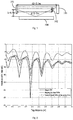
- the improvement brought about by the present invention with respect to field nulls is demonstrated below by means of a simulation; as Fig. 1 shows, this simulation constructs a three-path transmission scenario. Specifically, one path is from the reader 101 to the tag 102, another path is from the reader 101 to a metal reflector 103, and another path is from the reader 101 to a metal base 104.
- the distance d between the reader 101 and the tag 102 (also called the tag distance) is approximately 2 - 3 m, while the distance d2 between the reader 101 and the metal reflector 103 is 3.1 m.
- Fig. 2 uses three different schemes to simulate the relative path loss in the three-path transmission scenario shown in Fig. 1 , so as to compare the field nulls of these three schemes.
- scheme 1 only a single carrier is used; in scheme 2, two carriers are used with frequency hopping; in scheme 3, two carriers (865.7 MHz and 916.2 MHz) are used simultaneously.
- scheme 2 and 3 can both eliminate this field null.
- the field null problem can be ameliorated more effectively when a two-carrier scheme is used. It must be pointed out that the greater the difference in frequency between the two carriers, the better the frequency diversity result.
- Fig. 3 is a flow chart of the method by which an RFID reader locates a tag in one embodiment of the present invention, comprising the following steps: Step 301: the reader transmits a signal to a tag on at least two frequencies and receives a corresponding reflected signal.
- reflected signals from different tags are received at different times (e.g. time slots), and can be distinguished from one another by means of tag IDs. Further, in the case of more complex external environments, not only the signal reflected by the tag but also signals reflected from external reflective objects (i.e. other reflective objects besides the tag) will be received at a particular time.
- Step 302 the reflected signal received is subjected to a combining operation to obtain a combined received signal, which is then mapped onto a constellation diagram.
- the present invention proposes a new IQ mapping scheme in which at least two carriers are combined.
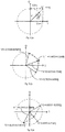
- Fig. 4 shows the vector sum of two carriers (continuous wave, CW) in the special IQ structure. As Fig. 4 shows, the new IQ mapping may be interpreted as the sum of two vectors on two carriers.
- each constellation point (dependent on f2 - f1) uniquely represents a tag distance in a particular zone.
- the reader transmits a signal to a tag at different times on a first frequency f1 and a second frequency f2, respectively.
- the reader receives a first received signal from the tag on the first frequency f1, and obtains a second received signal from the tag on the second frequency f2.
- the reader transmits a signal to a tag on a first frequency f1 and a second frequency f2 at the same time, i.e. the reader emits a combined transmission signal Acos(2 ⁇ f1*t)+Bcos(2 ⁇ f2*t).
- I1, I2, Q1 and Q2 on the two frequencies are combined in an arbitrary manner to obtain an I path local oscillator signal and a Q path local oscillator signal.
- the method of combining two carriers may be extended, for instance by combining a signal vector Vi on the i th carrier with a signal vector Vj on the j th carrier (e.g. by the method shown in Fig. 4 ) to obtain a signal vector Vm, then combining Vm with a signal vector Vk on the k th carrier, and so on until the signal vectors on all the carriers have been included in the combining operation, so as to obtain a final received signal vector V.
- the signal vector Vk on the k th carrier is combined with a signal vector Vp on a p th carrier to obtain a signal vector Vn, which is then combined with Vm.
- Step 303 the tag is located on the basis of the position of the constellation point of the received signal vector V on the constellation diagram; for instance, a corresponding tag distance d is determined.
- the tag distance d is determined on the basis of the vector angle ⁇ (see Fig. 4 ), each vector angle corresponding to one tag distance. It must be pointed out that the accuracy of the correspondence between vector angle and tag distance is dependent upon the difference in frequency between f2 and f1. With a smaller ⁇ f, the reader can determine tags within a larger range of distances, but with a larger error; with a larger ⁇ f, the reader can only determine tags within a smaller range of distances, with a correspondingly smaller error.
- ⁇ is the vector angle
- d is the tag distance
- c is the speed of light
- Q' sin(2 ⁇ f1*t 0 )+cos(2 ⁇ f2*t 0 ).
- the vector angle ⁇ is directly proportional to 2 d c f 2 ⁇ f 1 , so that the mapping of the combined received signal on the constellation diagram can uniquely represent tag distance over a larger range.
- Steps 304 - 305 are further performed: judging whether there is a need to determine tag distance d again, and if so, changing f1 and/or f2 so that the difference in frequency therebetween changes (e.g. ⁇ f increases) and repeating steps 301 - 303, so as to estimate tag distance with greater accuracy.
- the capacity for distance filtering of the special structure IQ provided in the present invention is dependent to a large degree on the difference in frequency f2 - f1 between the two carriers.
- the uniquely represented range of distances which can be obtained is larger.
- the range of distances which can be uniquely represented is smaller, but distances can be distinguished from one another with a high level of precision.
- Figs. 6(a) and 6(b) show two examples of the IQ structure defined in the present invention.
- the accuracy of distance mapping is not high, and the error arising from the fact that the constellation points have relatively small vector angles will result in a large divergence between the determined tag distance and the actual situation.
- the frequency difference is larger, and the range of distances which the IQ structure can map is 0 - 2.9 m, wherein 621 and 622 are 0 - 1 m while 623 and 624 are 1 m - 2.9 m, but the accuracy of distance mapping is higher.
- Fig. 7 shows the procedure of a method for performing N-stage distance filtering using different frequency combinations in one embodiment of the present invention, wherein N is any positive integer.
- N is 2, i.e. two different frequency combinations are used for tag filtering, such that the tag is filtered in two different ways, that is to say, coarsely and finely, so as to increase the accuracy of filtering.
- the use of two carriers with a relatively small frequency difference to determine tag distance is not the only way of performing coarse filtering; another way is to measure the average Received Signal Strength Indication (RSSI) value, and to filter out remote tags for which the RSSI value is too small.
- RSSI Received Signal Strength Indication
- the reader can repeat steps 301 - 303 N times (where N is any positive integer) according to a predetermined setting, so as to obtain the required tag distance. For example, after incrementing the number of tag locating operations performed by 1, the reader determines whether it has reached a preset number of times. If it has, the process is terminated or step 306 is performed; otherwise, the first frequency f1 and/or the second frequency f2 is/are changed to increase the difference in frequency therebetween, and the process returns to step 301. Alternatively, the reader compares the current tag location result with a historical tag location result (e.g.
- step 306 the reader can compare a preset difference value with the difference between the tag distance determined this time and the tag distance determined the previous time, so as to determine whether it is necessary to determine the tag distance d again.
- the reader may also decide how to change f2 and/or f1 according to a predetermined setting; this shall not be elaborated superfluously here.
- Step 306 is further performed: the reader performs filtering on the basis of the determined tag distance, and reports information about some or all tags located within a preset distance to a control center or host computer, at which point the process ends.
- the preset distance may be a range of distances, i.e. the reader reports information about tags located within this range of distances.
- the preset distance may be a single value, and the reader correspondingly reports information about tags for which the tag distance is less than the preset distance.
- the present invention can further distinguish between reflections from tags and from the external environment and determine tag distance during the communication process by analyzing the loci of constellation points in the IQ structure. It must be pointed out that a tag has two reflection states, unlike fixed reflections from the external environment, and the loci of the constellation points of these two states in the IQ structure will also be somewhat different.
- a metal plate (as an example of the external environment) is placed in front of the reader antenna.
- the metal plate always reflects signals completely, whereas the tag has two different reflective properties; for instance, the first state is complete signal reflection (which could be chip impedance open circuit or short circuit), while the second state is partial signal reflection (which could be matching of the chip impedance to the tag antenna, etc.).
- Fig. 8 is a schematic diagram of reflection states of metal and tag in this application scenario. Specifically, before a backscatter FM0/Miller code is emitted, the tag completely reflects the signal (i.e. state 1); when the backscatter FM0/Miller code is emitted (e.g. the EPC stage in Fig. 13 ), the tag will reflect LOW and HIGH alternately in the code, wherein partial reflection is manifested as LOW in the code (i.e. state 2) and complete reflection is manifested as HIGH in the code.
- Fig. 9 shows the loci of constellation points in the IQ structure for two different states.
- state 1 both metal and tag reflect completely, so the constellation point in the IQ structure moves between the position of the metal and the position of the tag, the loci thereof being within the range indicated by the dotted line in Fig. 9 .
- state 2 the tag only partially reflects, so the locus of the constellation point will be closer to the position of the metal (the range thereof being indicated by the solid line in Fig. 9 ), and the position of the tag cannot be reached.
- the position of the tag in the constellation diagram can be found.
- certain pattern recognition methods such as point clustering may also be used to distinguish between the position of the metal and the position of the tag in the IQ structure; on this basis, reflections from the tag can then be identified, and tag distance measured. It must be pointed out that the position of the metal and the position of the tag are each one constellation point on the constellation diagram.
- the above process can be carried out on the reader, and the tag information can be reported to the control center by the reader, the control center then finding the position of the tag on the constellation diagram on the basis of the tag information.
- a tag is placed at a position 0.33 m from the reader antenna, and a metal plate is placed at a position 0.8 m from the reader antenna.
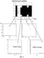
- Fig. 10 shows constellation diagrams captured during simulation for four different states.
- Fig. 10(a) shows a constellation point (0, 0) when there is no signal reflection.
- Fig. 10(c) shows a constellation point when there is simultaneous reflection from both the tag and the metal. It must be pointed out that this constellation point moves between the two constellation points corresponding to tag reflection only and metal reflection only; Fig.
- the tag location method it is further possible to track tagged moving targets in a reflective environment (e.g. a production environment). Specifically, the path of movement of the tag is estimated as follows:
- the method provided in the present invention transmits a signal to a tag on at least two carriers and correspondingly receives a reflected signal, combines the reflected signal received, and in turn locates the tag on the basis of the combined received signal.
- the present invention measures tag distance on the basis of the combined received signal, uses the tag distance obtained to filter out remote tags, and thereby reduces the ambiguity of tag filtering.
- the present invention uses the loci of combined received signals on a constellation diagram to distinguish between reflection from a tag and reflection from the surrounding environment (e.g. nearby metal), and will not be affected greatly by the surrounding environment.
- the present invention may also have multiple readers arranged to point in different directions, determine the tag distance d between a particular tag and each reader by the process shown in Fig. 3 , and obtain the coordinates in three dimensions of that tag on the basis of the multiple tag distances d, so as to more accurately ascertain the location of the tag.
- the present invention provides multiple radio frequency identification (RFID) readers suitable for use with the above tag locating method, comprising: a control unit, for directing a frequency generation unit to generate at least two frequencies; and a signal transmission unit, for transmitting a signal to the tag on the at least two frequencies generated.
- the control unit is further used for: subjecting a reflected signal received by a signal receiving unit to a combining operation to obtain a combined received signal, and mapping the combined received signal to a constellation point on a constellation diagram for the purpose of locating the tag.
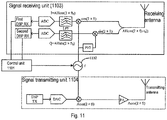
- Fig. 11 is a schematic diagram of the TX/RX chain of a reader in one embodiment of the present invention.
- the software and/or hardware of an ordinary reader is modified and upgraded in a simple manner, enabling it to measure tag distance, and in turn to filter tags or determine the path of movement of a tag on the basis of the tag distance d obtained.
- the reader comprises at least one of the following units: a control unit 1101, a frequency generation unit 1102, a signal receiving unit 1103 and a signal transmission unit 1104.
- a signal obtained by a receiving (RX) antenna through communication with a particular tag is split into two lines.
- One line is mixed with a signal cos(2 ⁇ ft) generated by the frequency generation unit 1102 before being processed in a low-pass filter (LPF) and an analog-to-digital conversion (ADC) module, and then supplied to the control unit 1101 by a first receiving digital signal processing (DSP RX) module.
- Another line is mixed with a signal sin(2 ⁇ ft) obtained by subjecting a signal generated by the frequency generation unit 1102 to phase-shift processing, processed in an LPF and ADC module, and then supplied to the control unit 1101 by a second DSP RX module.
- H reflects signal attenuation and circuit effects.
- the first time and the second time are different.
- a transmitting digital signal processing (DSP TX) module sends a signal to a digital-to-analog conversion (DAC) module for processing; after passing through a mixer and an amplifier, the signal is output to the transmitting (TX) antenna.
- DSP TX digital signal processing
- DAC digital-to-analog conversion
- the control unit 1101 is used for directing the frequency generation unit 1102 to generate the first frequency f1 and second frequency f2 at different times, for the purpose of transmitting signals to the tag.
- the frequency generation unit 1102 is an oscillator.
- the normalization operation is by no means essential; the signal received by the control unit 1101 may be a normalized first in-phase component I1 and normalized first quadrature component Q1.
- the first in-phase component may be pre-normalization I1' or post-normalization I1, or I1' may be equal to I1.
- the second in-phase component may be pre-normalization 12' or post-normalization 12, or 12' may be equal to 12. The situation is similar for the second quadrature component.
- control unit 1101 is used for mapping the combined received signal vector V onto a constellation diagram, and thereby determining the distance between the reader and the tag (also called tag distance d) on the basis of the IQ structure.
- control unit 1101 may be a hardware unit (e.g. an a newly added MCU), or a software module, and so is easily added to the ordinary reader.
- the reader provided in this embodiment must change frequency before obtaining the tag distance, and 20 ms are required for phase-locked loop (PLL) locking when the frequency is changed.
- PLL phase-locked loop
- the distance moved by a tag in this period of time will not be too large (e.g. just 4 cm when the speed of movement reaches 2 m/s), and so the accuracy of distance filtering will not be affected.
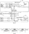
- Fig. 12 is a schematic diagram of the structure of a dual-carrier reader in another embodiment of the present invention; new hardware units for transmitting two CWs simultaneously have been added to the reader.
- the reader in Fig. 12 comprises: a control unit (which may be an MCU, etc.) 1201, a frequency generation unit 1202, a signal receiving unit 1203 and a signal transmission unit 1204, and may further comprise: a signal attenuation unit 1205.
- the first DSP RX, second DSP RX, MCU, first DSP TX and second DSP TX form the digital processing part of the reader.
- a first transmission signal Acos(2 ⁇ f1*t is generated on f1 and a second transmission signal Bcos(2 ⁇ f2*t) is generated on f2; these two signals are combined, and the transmission signal finally sent to the transmitting antenna is Acos(2 ⁇ f1*t)+Bcos(2 ⁇ f2*t). Since the channel attenuation and circuit impact of each channel are different, the backscattered signal received from a tag is: AH1*cos(2 ⁇ f1*(t-t 0 ))+BH2*cos(2 ⁇ f2*(t-t 0 )).
- LO local oscillator
- I ′ Acos 2 ⁇ f 1 * t 0 + Bsin 2 ⁇ f 2 * t 0
- Q ′ Asin 2 ⁇ f 1 * t 0 + Bcos 2 ⁇ f 2 * t 0
- An IQ structure to be used for distance filtering may then be constructed from these I and Q values.
- H1 is the channel attenuation and circuit impact on the first frequency f1
- H2 is the channel attenuation and circuit impact on the second frequency f2.
- a training process e.g. channel estimation
- AGC automatic gain control
- Fig. 13 shows the channel estimation process for a reader in one embodiment of the present invention. Specifically, the reader emits a query signal, and transmits a signal on the first frequency f1 in order to estimate the signal attenuation on f1 (including channel attenuation and circuit impact, etc.).
- the reader then emits an ACK signal, and transmits a signal on the second frequency f2 in order to estimate the signal attenuation on f2.
- the reader then emits another ACK signal, and transmits a signal on the first frequency f1 and the second frequency f2 simultaneously to measure tag distance.
- the reader first estimates signal attenuation on each carrier (f1 and f2) separately by communicating with the tag, and then emits a signal on f1 and f2 to measure tag distance.
- the MCU suppresses signal transmission on the second frequency f2 by controlling the second GC; similarly, when the second signal attenuation H2 is being estimated, the MCU suppresses signal transmission on the first frequency f1 by controlling the first GC.
- the tag locating method and reader provided in the embodiments of the present invention comprise at least one of the following solutions:
Landscapes
- Engineering & Computer Science (AREA)
- Physics & Mathematics (AREA)
- Remote Sensing (AREA)
- Radar, Positioning & Navigation (AREA)
- General Physics & Mathematics (AREA)
- Toxicology (AREA)
- Health & Medical Sciences (AREA)
- Theoretical Computer Science (AREA)
- Computer Vision & Pattern Recognition (AREA)
- Artificial Intelligence (AREA)
- General Health & Medical Sciences (AREA)
- Electromagnetism (AREA)
- Computer Networks & Wireless Communication (AREA)
- Radar Systems Or Details Thereof (AREA)
Claims (12)
- Verfahren zum Lokalisieren eines Transponders unter Verwendung eines Radio Frequency Identification (RFTD)-Lesegerätes, umfassend:A. das Lesegerät sendet ein Signal an den Transponder auf mindestens zwei Frequenzen und empfängt ein entsprechendes reflektiertes Signal;B. Einspeisen des empfangenen reflektierten Signals in eine Kombinierungsoperation, um ein kombiniertes empfangenes Signal zu erhalten, und Abbilden des kombinierten empfangenen Signals auf einen Konstellationspunkt in einem Konstellationsdiagramm zum Zweck des Lokalisierens des Transponders;wobei die mindestens zwei Frequenzen eine erste Frequenz f1 und eine zweite Frequenz f2 umfassen; und der Schritt des Empfangens eines entsprechenden reflektierten Signals in Schritt A Folgendes umfasst:das Lesegerät erhält ein erstes empfangenes Signal auf der ersten Frequenz f1 an einem ersten Zeitpunkt underhält ein zweites empfangenes Signal auf der zweiten Frequenz f2 an einem zweiten Zeitpunkt, wobei der erste Zeitpunkt und der zweite Zeitpunkt voneinander verschieden sind; undwobei der Schritt des Einspeisens des empfangenen reflektierten Signals in eine Kombinierungsoperation zum Erhalten eines kombinierten empfangenen Signals in Schritt B Folgendes umfasst:dadurch gekennzeichnet, dass es des Weiteren Folgendes umfasst:B1. Erhalten einer ersten phasengleichen Komponente I1 und einer ersten Quadraturkomponente Q1 aus dem ersten empfangenen Signal, um einen ersten Signalvektor V1 = I1 + jQ1 zu konstruieren;B2. Erhalten einer zweiten phasengleichen Komponente I2 und einer zweiten Quadraturkomponente Q2 aus dem zweiten empfangenen Signal, um einen zweiten Signalvektor V2 = Q2 + jI2 zu konstruieren;
B3. Addieren des ersten Signalvektors V1 und des zweiten Signalvektors V2 miteinander zum Erhalten eines kombinierten empfangenen Signalvektors V,
wobei der Schritt des Abbildens des kombinierten empfangenen Signals auf einen Konstellationspunkt in einem Konstellationsdiagramm zum Zweck des Lokalisierens des Transponders in Schritt B Folgendes umfasst:
Bestimmen der Transponderdistanz d zwischen dem Transponder und dem Lesegerät auf der Basis einer Korrelation zwischen der Transponderdistanz d und dem Winkel θ des kombinierten empfangenen Signalvektors V. - Verfahren zum Lokalisieren eines Transponders unter Verwendung eines Radio Frequenz Identification (RFID)-Lesegerätes, umfassend:A. das Lesegerät sendet ein Signal an den Transponder auf mindestens zwei Frequenzen und empfängt ein entsprechendes reflektiertes Signal;B. Einspeisen des empfangenen reflektierten Signals in eine Kombinierungsoperation zum Erhalten eines kombinierten empfangenen Signals, und Abbilden des kombinierten empfangenen Signals auf einen Konstellationspunkt in einem Konstellationsdiagramm zum Zweck des Lokalisierens des Transponders; wobei die mindestens zwei Frequenzen eine erste Frequenz f1 und eine zweite Frequenz f2 umfassen; und der Schritt, in dem das Lesegerät in Schritt A ein Signal an den Transponder auf mindestens zwei Frequenzen sendet, Folgendes umfasst:das Lesegerät generiert ein erstes Übertragungssignal Acos(2πf1*t) auf der ersten Frequenz f1, generiert ein zweites Übertragungssignal Bcos(2πf2*t) auf der zweiten Frequenz f2, und sendet ein kombiniertes Übertragungssignal Acos(2πf1*t)+Bcos(2πf2*t) an den Transponder;dadurch gekennzeichnet, dass der Schritt des Einspeisens des empfangenen reflektierten Signals in eine Kombinierungsoperation zum Erhalten eines kombinierten empfangenen Signals in Schritt B Folgendes umfasst:das Lesegerät mischt das empfangene reflektierte Signal mit einem I-Pfad-Überlagerungsoszillator-Signal

 und erhält das kombinierte empfangene Signal auf der Basis der kombinierten phasengleichen Komponente Inew und der kombinierten Quadraturkomponente Qnew;wobei das H1 eine erste Signaldämpfung auf der ersten Frequenz f1 ist und das H2 eine zweite Signaldämpfung auf der zweiten Frequenz f2 ist, und wobei der Schritt des Abbildens des kombinierten empfangenen Signals auf einen Konstellationspunkt in einem Konstellationsdiagramm zum Zweck des Lokalisierens des Transponders in Schritt B Folgendes umfasst:
Bestimmen der Transponderdistanz d zwischen dem Transponder und dem Lesegerät auf der Basis einer Korrelation zwischen der Transponderdistanz d und dem Winkel θ des kombinierten empfangenen Signalvektors V. - Verfahren nach einem der Ansprüche 1 und 2, dadurch gekennzeichnet, dass es vor dem Schritt A des Weiteren Folgendes umfasst:
C. Einstellen der ersten Frequenz f1 und der zweiten Frequenz f2, die voneinander verschieden sind;
wobei das Verfahren nach dem Schritt B des Weiteren Folgendes umfasst:
D. nach dem Inkrementieren der Anzahl ausgeführter Transponderlokalisierungsoperationen um 1, Bestimmen, ob eine voreingestellte Schwelle erreicht wurde; wenn ja, dann Beenden des Prozesses, anderenfalls Ändern der ersten Frequenz f1 und/oder der zweiten Frequenz f2, um die Frequenzdifferenz zwischen beiden zu erhöhen, und Zurückkehren zu Schritt A; oder
das Verfahren nach dem Schritt B des Weiteren Folgendes umfasst:
E. Vergleichen des momentanen Transponderstandortresultats mit einem historischen Transponderstandortresultat und, falls die Differenz zwischen beiden niedriger ist als eine voreingestellte Schwelle, dann Beenden des Prozesses, anderenfalls Ändern der ersten Frequenz f1 und/oder der zweiten Frequenz f2, um die Frequenzdifferenz zwischen beiden zu erhöhen, und Zurückkehren zu Schritt A. - Verfahren nach Anspruch 1, dadurch gekennzeichnet, dass die Korrelation zwischen der Transponderdistanz d und dem Konstellationspunkt-Vektorwinkel θ folgendermaßen ist: der Vektorwinkel θ des Konstellationspunktes verhält sich direkt proportional zu

- Verfahren nach einem der Ansprüche 1 und 2, dadurch gekennzeichnet, dass es des Weiteren umfasst, dass das Lesegerät die Transponderdistanz d eines oder mehrerer Transponder mit einer voreingestellten Schwelle vergleicht und Informationen über jeden Transponder, bei dem die Transponderdistanz d mit der voreingestellten Schwelle übereinstimmt, an eine Steuerungszentrale berichtet.
- Verfahren nach einem der Ansprüche 1 und 2, dadurch gekennzeichnet, dass der Schritt des Abbildens des kombinierten empfangenen Signals auf einen Konstellationspunkt in einem Konstellationsdiagramm zum Zweck des Lokalisierens des Transponders in Schritt B Folgendes umfasst:Messen der Transponderdistanz d des Transponders an verschiedenen Positionen auf der ersten Frequenz f1 und der zweiten Frequenz f2;Bestimmen der Bewegungsgeschwindigkeit des Transponders auf der Basis der Distanz zwischen den Positionen und der Bewegungszeit des Transponder; undSchätzen des Bewegungspfades des Transponders auf der Basis unterschiedlicher detektierter Positionen und der Bewegungsgeschwindigkeit.
- Verfahren nach einem der Ansprüche 1 und 2, dadurch gekennzeichnet, dass es des Weiteren Folgendes umfasst: Anordnen mehrerer Lesegeräte dergestalt, dass sie in verschiedene Richtungen weisen, Bestimmen der Transponderdistanz d zwischen dem Transponder und jedem Lesegerät und Erhalten von Koordinaten des Transponders in drei Dimensionen auf der Basis der mehreren Transponderdistanzen d.
- Verfahren nach einem der Ansprüche 1 und 2, dadurch gekennzeichnet, dass es vor dem Schritt A des Weiteren Folgendes umfasst: das Lesegerät misst den durchschnittlichen Received Signal Strength Indication (RSSI)-Wert und filtert Transponder heraus, bei denen der tatsächliche RSSI-Wert niedriger ist als der durchschnittliche RSSI-Wert.
- Radio Frequenz Identification (RFID)-Lesegerät, umfassend:eine Steuereinheit, um eine Frequenzgenerierungseinheit anzuweisen, mindestens zwei Frequenzen zu generieren;eine Signalsendeeinheit zum Senden eines Signals an einen Transponder auf den generierten mindestens zwei Frequenzen;wobei die Steuereinheit dafür ausgestaltet ist, ein durch eine Signalempfangseinheit empfangenes reflektiertes Signal einer Kombinierungsoperation zu unterziehen, um ein kombiniertes empfangenes Signal zu erhalten, und das kombinierte empfangene Signal auf einen Konstellationspunkt in einem Konstellationsdiagramm zum Zweck des Lokalisierens des Transponders abzubilden;wobei die mindestens zwei Frequenzen eine erste Frequenz f1 und eine zweite Frequenz f2 umfassen;wobei die Signalempfangseinheit dafür ausgestaltet ist, ein erstes empfangenes Signal auf der ersten Frequenz f1 an einem ersten Zeitpunkt zu erhalten und ein zweites empfangenes Signal auf der zweiten Frequenz f2 an einem zweiten Zeitpunkt zu erhalten, wobei der erste Zeitpunkt und der zweite Zeitpunkt voneinander verschieden sind; undwobei die Steuereinheit des Weiteren für Folgendes ausgestaltet ist:Erhalten einer ersten phasengleichen Komponente I1 und einer ersten Quadraturkomponente Q1 aus dem ersten empfangenen Signal, um einen ersten Signalvektor V1 = I1 + jQ1 zu konstruieren;Erhalten einer zweiten phasengleichen Komponente I2 und einer zweiten Quadraturkomponente Q2 aus dem zweiten empfangenen Signal, um einen zweiten Signalvektor V2 = Q2 + jI2 zu konstruieren;dadurch gekennzeichnet, dass die Steuereinheit des Weiteren für Folgendes ausgestaltet ist:Addieren des ersten Signalvektors V1 und des zweiten Signalvektors V2 miteinander zum Erhalten eines kombinierten empfangenen Signalvektors V, undBestimmen der Transponderdistanz d zwischen dem Transponder und dem Lesegerät auf der Basis einer Korrelation zwischen der Transponderdistanz d und dem Winkel θ des kombinierten empfangenen Signalvektors V, wenn das kombinierte empfangene Signal auf einen Konstellationspunkt in einem Konstellationsdiagramm zum Zweck des Lokalisierens des Transponders abgebildet wird.
- Radio Frequenz Identification (RFID)-Lesegerät, umfassend: eine Steuereinheit, um eine Frequenzgenerierungseinheit anzuweisen, mindestens zwei Frequenzen zu generieren; eine Signalsendeeinheit zum Senden eines Signals an einen Transponder auf den generierten mindestens zwei Frequenzen; wobei die Steuereinheit dafür ausgestaltet ist, ein durch eine Signalempfangseinheit empfangenes reflektiertes Signal einer Kombinierungsoperation zu unterziehen, um ein kombiniertes empfangenes Signal zu erhalten, und das kombinierte empfangene Signal auf einen Konstellationspunkt in einem Konstellationsdiagramm zum Zweck des Lokalisierens des Transponders abzubilden; wobei:wobei die mindestens zwei Frequenzen eine erste Frequenz f1 und eine zweite Frequenz f2 umfassen;die Signalsendeeinheit dafür verwendet wird, ein erstes Übertragungssignal Acos(2πf1*t) auf der ersten Frequenz f1 zu generieren, ein zweites Übertragungssignal Bcos(2π2*t) auf der zweiten Frequenz f2 zu generieren, und ein kombiniertes Übertragungssignal Acos(2πf1*t)+Bcos(2π2*t) auszusenden,wobei die Signalempfangseinheit ein erstes Empfangsmodul und ein zweites Empfangsmodul umfasst;dadurch gekennzeichnet dass:das erste Empfangsmodul dafür verwendet wird, ein durch eine Empfangsantenne erhaltenes Signal mit einem I-Pfad-Überlagerungsoszillator-Signal
 das zweite Empfangsmodul dafür verwendet wird, ein durch die Empfangsantenne erhaltenes Signal mit einem Q-Pfad-Überlagerungsoszillator-Signal
 die Steuereinheit dafür verwendet wird, das kombinierte empfangene Signal auf der Basis der kombinierten phasengleichen Komponente Inew und der kombinierten Quadraturkomponente Qnew zu erhalten;wobei das H1 eine erste Signaldämpfung auf der ersten Frequenz f1 ist und das H2 eine zweite Signaldämpfung auf der zweiten Frequenz f2 ist und wobei das Abbilden des kombinierten empfangenen Signals auf einen Konstellationspunkt in einem Konstellationsdiagramm zum Zweck des Lokalisierens des Transponders Folgendes umfasst:
Bestimmen der Transponderdistanz d zwischen dem Transponder und dem Lesegerät auf der Basis einer Korrelation zwischen der Transponderdistanz d und dem Winkel θ des kombinierten empfangenen Signalvektors V. - Lesegerät nach Anspruch 10, dadurch gekennzeichnet, dass es des Weiteren Folgendes umfasst:eine Signaldämpfungseinheit;wobei die Steuereinheit dafür verwendet wird, die Signalsendeeinheit anzuweisen, ein Signal auf der ersten Frequenz f1 zu senden, um H1 durch Kanalschätzung zu erhalten, und die Signaldämpfungseinheit anzuweisen, einen ersten Dämpfungsfaktor G1 = /H1 für die erste Frequenz f1 zu generieren, und die Signalsendeeinheit anzuweisen, ein Signal auf der zweiten Frequenz f2 zu senden, um H2 durch Kanalschätzung zu erhalten, und die Signaldämpfungseinheit anzuweisen, einen zweiten Dämpfungsfaktor G2 = 1/H2 für die zweite Frequenz f2 zu generieren.
- Lesegerät nach einem der Ansprüche 9-11, dadurch gekennzeichnet, dass die Steuereinheit des Weiteren für Folgendes ausgestaltet ist:
Anweisen der Frequenzgenerierungseinheit, die erste Frequenz f1 und/oder die zweite Frequenz f2 zu ändern, um die Frequenzdifferenz zwischen beiden zu erhöhen, und Anweisen der Signalsendeeinheit, ein Signal an den Transponder auf der ersten Frequenz f1 und der zweiten Frequenz f2 nach der Änderung zu senden.
Applications Claiming Priority (1)
| Application Number | Priority Date | Filing Date | Title |
|---|---|---|---|
| PCT/CN2011/070279 WO2012094825A1 (zh) | 2011-01-14 | 2011-01-14 | 采用射频识别阅读器定位标签的方法以及射频识别阅读器 |
Publications (3)
| Publication Number | Publication Date |
|---|---|
| EP2648131A1 EP2648131A1 (de) | 2013-10-09 |
| EP2648131A4 EP2648131A4 (de) | 2015-01-07 |
| EP2648131B1 true EP2648131B1 (de) | 2018-10-17 |
Family
ID=46506766
Family Applications (1)
| Application Number | Title | Priority Date | Filing Date |
|---|---|---|---|
| EP11855446.8A Not-in-force EP2648131B1 (de) | 2011-01-14 | 2011-01-14 | Verfahren und Gerät zur Ortung von RFID-Tags |
Country Status (4)
| Country | Link |
|---|---|
| US (1) | US9195862B2 (de) |
| EP (1) | EP2648131B1 (de) |
| CN (1) | CN103329142B (de) |
| WO (1) | WO2012094825A1 (de) |
Families Citing this family (31)
| Publication number | Priority date | Publication date | Assignee | Title |
|---|---|---|---|---|
| CN103682635B (zh) * | 2012-09-25 | 2016-01-13 | 西门子公司 | 一种射频识别天线、射频识别天线的控制单元及控制方法和射频识别系统 |
| US20140113652A1 (en) * | 2012-10-24 | 2014-04-24 | Yael G. Maguire | Sensing Distance Between Wireless Devices Using Multiple Scales of Controlled Bandwidth |
| US20160139238A1 (en) * | 2013-06-20 | 2016-05-19 | Qatar University Qstp-B | System and method for rfid indoor localization |
| US20160132561A1 (en) * | 2013-06-28 | 2016-05-12 | Hewlett-Packard Development Company, L.P. | Expiration tag of data |
| CN104951815B (zh) * | 2014-03-31 | 2018-08-21 | 西门子(中国)有限公司 | 射频识别读写器及其天线组件和读写部件 |
| CN104709696B (zh) * | 2014-12-31 | 2018-03-16 | 深圳市中智科创机器人有限公司 | 托盘堆垛车放置/提取货物的方法、装置以及系统 |
| US9767330B2 (en) * | 2015-07-16 | 2017-09-19 | Empire Technology Development Llc | Distance determination between RFID tags |
| CN105572413B (zh) * | 2015-12-31 | 2019-02-05 | 智坤(江苏)半导体有限公司 | 一种测量无源uhf rfid标签移动速度和方向的方法与应用 |
| KR102417610B1 (ko) * | 2016-03-03 | 2022-07-07 | 삼성전자주식회사 | 근거리 초고주파 레이더를 이용한 코드 판독 방법 및 장치 |
| US20170017874A1 (en) * | 2016-05-06 | 2017-01-19 | Qualcomm Incorporated | Radio frequency identification (rfid) reader with frequency adjustment of continuous radio frequency (rf) wave |
| DE102016209583A1 (de) | 2016-06-01 | 2017-12-21 | Phoenix Contact Gmbh & Co. Kg | Produktionsanlage zum Herstellen einer Vielzahl von Artikeln und Verfahren zum Steuern und/oder Überwachen der Produktionsanlage |
| US10498569B2 (en) * | 2016-06-23 | 2019-12-03 | University Of Massachusetts | Systems and methods for backscatter communication |
| CN106291461B (zh) * | 2016-09-30 | 2019-01-11 | 香港中文大学深圳研究院 | 一种rfid室内定位的方法、装置、服务器及系统 |
| CN107886018B (zh) * | 2016-09-30 | 2021-01-29 | 西门子公司 | 判断标签移动方向的方法和装置 |
| EP3373192B1 (de) * | 2017-03-07 | 2019-09-18 | Denso Wave Incorporated | Etikettenleser |
| JP6887838B2 (ja) * | 2017-03-21 | 2021-06-16 | 東芝テック株式会社 | 情報処理装置、情報収集装置および情報収集システム |
| WO2019046274A1 (en) | 2017-08-30 | 2019-03-07 | Cummins Filtration Ip, Inc. | LOCK FOR AUTHENTIC FILTER RECOGNITION |
| US10656263B2 (en) | 2017-09-14 | 2020-05-19 | Qualcomm Incorporated | Extended localization range and assets tracking |
| US10962632B2 (en) * | 2017-12-18 | 2021-03-30 | Texas Instruments Incorporated | Electronic device and method for low power RF ranging |
| EP3652559B1 (de) * | 2018-03-24 | 2025-09-17 | Li, Brandon | Rfid-tag-erkennung |
| US11506777B2 (en) | 2018-03-24 | 2022-11-22 | Brandon Li | RFID tag location and association of RFID tags |
| JP7107762B2 (ja) * | 2018-06-20 | 2022-07-27 | 東芝テック株式会社 | 通信装置、通信方法及びプログラム |
| US10956692B2 (en) | 2018-11-27 | 2021-03-23 | Geissler Companies, Llc | Tag reader receiver with high-Q antenna |
| US10972151B2 (en) | 2018-11-27 | 2021-04-06 | Geissler Companies, Llc | Tag reader transmitter with high-Q antenna |
| US10976408B2 (en) * | 2018-12-28 | 2021-04-13 | Zebra Technologies Corporation | Methods and system for enhanced RFID direction finding |
| EP3767518A1 (de) * | 2019-07-15 | 2021-01-20 | Sick Ag | Rfid-vorrichtung und verfahren zum kommunizieren mit einem rfid-transponder |
| CN110687504B (zh) * | 2019-09-06 | 2022-04-29 | 天津大学 | 基于多频载波相位差的uhf rfid标签测距方法 |
| CN110995626B (zh) * | 2019-10-11 | 2020-12-22 | 清华大学 | 并发信道参数估计方法、系统、电子设备和存储介质 |
| CN112949328A (zh) * | 2019-12-11 | 2021-06-11 | 上海烨煊信息技术有限公司 | 工业级超高频rfid读写装置及rfid射频识别系统 |
| WO2022165593A1 (en) * | 2021-02-03 | 2022-08-11 | Bitstrata Systems Inc. | Radar-based sensing, positioning, and communications system |
| CN113468899B (zh) * | 2021-06-30 | 2023-06-16 | 中国科学技术大学 | 一种基于rfid的不携带标签的目标追踪方法 |
Family Cites Families (14)
| Publication number | Priority date | Publication date | Assignee | Title |
|---|---|---|---|---|
| USRE42643E1 (en) * | 1991-03-27 | 2011-08-23 | Panasonic Corporation | Communication system |
| US5471508A (en) * | 1993-08-20 | 1995-11-28 | Hitachi America, Ltd. | Carrier recovery system using acquisition and tracking modes and automatic carrier-to-noise estimation |
| US20080048867A1 (en) | 2006-01-18 | 2008-02-28 | Oliver Ronald A | Discontinuous-Loop RFID Reader Antenna And Methods |
| US7714773B2 (en) | 2006-03-28 | 2010-05-11 | Omron Corporation | RFID tag distance measuring system and reader |
| US7787568B2 (en) * | 2006-06-22 | 2010-08-31 | Symbol Technologies, Inc. | High bit rate RFID system |
| JP2008199411A (ja) | 2007-02-14 | 2008-08-28 | Omron Corp | 周波数切替装置装置及びこれを利用したrfidシステム、距離測定装置 |
| CN101046843A (zh) * | 2007-04-30 | 2007-10-03 | 郭岳衡 | 无线射频识别定位方法及其系统 |
| GB0709313D0 (en) * | 2007-05-15 | 2007-06-20 | Siemens Ag | RFID reader |
| JP5071800B2 (ja) * | 2008-02-06 | 2012-11-14 | ブラザー工業株式会社 | 無線タグ探索装置 |
| JP2009270901A (ja) * | 2008-05-07 | 2009-11-19 | Yoichi Kaneko | パッシブrfidタグの三次元位置を高精度に計測する方法 |
| US20110109440A1 (en) * | 2008-07-02 | 2011-05-12 | Nxp B.V. | System for reading information transmitted from a transponder |
| CN101587182B (zh) * | 2009-06-25 | 2011-08-17 | 华南理工大学 | 一种用于rfid室内定位系统的定位方法 |
| CN101604021B (zh) | 2009-07-09 | 2012-05-09 | 复旦大学 | 一种无线射频识别系统的定位方法与装置 |
| CN101853413B (zh) * | 2010-03-12 | 2014-09-17 | 北京创毅视讯科技有限公司 | 一种应用于物联网的电子标签及使用该电子标签的系统 |
-
2011
- 2011-01-14 EP EP11855446.8A patent/EP2648131B1/de not_active Not-in-force
- 2011-01-14 CN CN201180064886.0A patent/CN103329142B/zh not_active Expired - Fee Related
- 2011-01-14 US US13/979,838 patent/US9195862B2/en active Active
- 2011-01-14 WO PCT/CN2011/070279 patent/WO2012094825A1/zh not_active Ceased
Non-Patent Citations (1)
| Title |
|---|
| None * |
Also Published As
| Publication number | Publication date |
|---|---|
| CN103329142A (zh) | 2013-09-25 |
| EP2648131A1 (de) | 2013-10-09 |
| EP2648131A4 (de) | 2015-01-07 |
| US9195862B2 (en) | 2015-11-24 |
| US20140022059A1 (en) | 2014-01-23 |
| WO2012094825A1 (zh) | 2012-07-19 |
| CN103329142B (zh) | 2016-01-13 |
Similar Documents
| Publication | Publication Date | Title |
|---|---|---|
| US9195862B2 (en) | Radio frequency identification reader and a method for locating a tag by the radio frequency identification reader | |
| Buffi et al. | A phase-based technique for localization of UHF-RFID tags moving on a conveyor belt: Performance analysis and test-case measurements | |
| US9581689B2 (en) | Reader/writer and article sorting system | |
| US9881473B1 (en) | RFID loss-prevention using angle-of-arrival | |
| KR101038617B1 (ko) | 거리 측정 장치, 거리 측정 방법, 반사체 및 통신 시스템 | |
| US11874365B2 (en) | Passive radio frequency identification ranging | |
| US8188908B2 (en) | System and method for measurement of distance to a tag by a modulated backscatter RFID reader | |
| US7932814B2 (en) | Method and system to determine physical parameters as between a RFID tag and a reader | |
| US8907767B2 (en) | Methods and apparatus for distance determination for radiofrequency identification devices | |
| Buffi et al. | The SARFID technique for discriminating tagged items moving through a UHF-RFID gate | |
| CN109765547A (zh) | 一种无源rfid精确测距方法及系统 | |
| CN107066913A (zh) | 一种基于rfid技术的倒置货物检测方法 | |
| Sović et al. | Particle filtering for indoor RFID tag tracking | |
| EP2533173B1 (de) | Verfahren zur Ortsbestimmung eines sich bewegenden RFID Tags | |
| Ryoo et al. | Phase-based ranging of rfid tags with applications to shopping cart localization | |
| US20070063818A1 (en) | Automatic data collection device, method and article for avoiding interference | |
| US20200259571A1 (en) | Transceiver and method for distance measurement | |
| Bolić et al. | Performance of passive UHF RFID systems in practice | |
| CN110687504A (zh) | 基于多频载波相位差的uhf rfid标签测距方法 | |
| Buffi et al. | A phase-based technique for discriminating tagged items moving through a UHF-RFID gate | |
| Böller et al. | SHF RFID based Localization: Combining Time-of-Flight and Angle-of-Arrival | |
| JP5518320B2 (ja) | リーダライタシステム、及び物品仕分システム | |
| Decarli et al. | Introduction to Radio-Frequency Identification (RFID) and RFID Positioning | |
| Wang et al. | An RFID Localization System for Smart Logistics | |
| Kumbul et al. | Indoor localization with passive RFID system based on phase difference of displacement |
Legal Events
| Date | Code | Title | Description |
|---|---|---|---|
| PUAI | Public reference made under article 153(3) epc to a published international application that has entered the european phase |
Free format text: ORIGINAL CODE: 0009012 |
|
| 17P | Request for examination filed |
Effective date: 20130703 |
|
| AK | Designated contracting states |
Kind code of ref document: A1 Designated state(s): AL AT BE BG CH CY CZ DE DK EE ES FI FR GB GR HR HU IE IS IT LI LT LU LV MC MK MT NL NO PL PT RO RS SE SI SK SM TR |
|
| DAX | Request for extension of the european patent (deleted) | ||
| A4 | Supplementary search report drawn up and despatched |
Effective date: 20141209 |
|
| RIC1 | Information provided on ipc code assigned before grant |
Ipc: G06K 7/10 20060101ALI20141203BHEP Ipc: G01S 13/84 20060101AFI20141203BHEP Ipc: G01S 13/75 20060101ALN20141203BHEP |
|
| RAP1 | Party data changed (applicant data changed or rights of an application transferred) |
Owner name: SIEMENS AKTIENGESELLSCHAFT |
|
| REG | Reference to a national code |
Ref country code: DE Ref legal event code: R079 Ref document number: 602011053085 Country of ref document: DE Free format text: PREVIOUS MAIN CLASS: G06K0007100000 Ipc: G01S0013840000 |
|
| RIC1 | Information provided on ipc code assigned before grant |
Ipc: G01S 13/75 20060101ALN20180507BHEP Ipc: G01S 13/84 20060101AFI20180507BHEP Ipc: G06K 7/10 20060101ALI20180507BHEP |
|
| GRAP | Despatch of communication of intention to grant a patent |
Free format text: ORIGINAL CODE: EPIDOSNIGR1 |
|
| STAA | Information on the status of an ep patent application or granted ep patent |
Free format text: STATUS: GRANT OF PATENT IS INTENDED |
|
| INTG | Intention to grant announced |
Effective date: 20180626 |
|
| GRAS | Grant fee paid |
Free format text: ORIGINAL CODE: EPIDOSNIGR3 |
|
| GRAA | (expected) grant |
Free format text: ORIGINAL CODE: 0009210 |
|
| STAA | Information on the status of an ep patent application or granted ep patent |
Free format text: STATUS: THE PATENT HAS BEEN GRANTED |
|
| AK | Designated contracting states |
Kind code of ref document: B1 Designated state(s): AL AT BE BG CH CY CZ DE DK EE ES FI FR GB GR HR HU IE IS IT LI LT LU LV MC MK MT NL NO PL PT RO RS SE SI SK SM TR |
|
| REG | Reference to a national code |
Ref country code: GB Ref legal event code: FG4D |
|
| REG | Reference to a national code |
Ref country code: CH Ref legal event code: EP |
|
| REG | Reference to a national code |
Ref country code: IE Ref legal event code: FG4D |
|
| REG | Reference to a national code |
Ref country code: DE Ref legal event code: R096 Ref document number: 602011053085 Country of ref document: DE Ref country code: AT Ref legal event code: REF Ref document number: 1054688 Country of ref document: AT Kind code of ref document: T Effective date: 20181115 |
|
| REG | Reference to a national code |
Ref country code: NL Ref legal event code: MP Effective date: 20181017 |
|
| REG | Reference to a national code |
Ref country code: LT Ref legal event code: MG4D |
|
| REG | Reference to a national code |
Ref country code: AT Ref legal event code: MK05 Ref document number: 1054688 Country of ref document: AT Kind code of ref document: T Effective date: 20181017 |
|
| PG25 | Lapsed in a contracting state [announced via postgrant information from national office to epo] |
Ref country code: NL Free format text: LAPSE BECAUSE OF FAILURE TO SUBMIT A TRANSLATION OF THE DESCRIPTION OR TO PAY THE FEE WITHIN THE PRESCRIBED TIME-LIMIT Effective date: 20181017 |
|
| PG25 | Lapsed in a contracting state [announced via postgrant information from national office to epo] |
Ref country code: BG Free format text: LAPSE BECAUSE OF FAILURE TO SUBMIT A TRANSLATION OF THE DESCRIPTION OR TO PAY THE FEE WITHIN THE PRESCRIBED TIME-LIMIT Effective date: 20190117 Ref country code: PL Free format text: LAPSE BECAUSE OF FAILURE TO SUBMIT A TRANSLATION OF THE DESCRIPTION OR TO PAY THE FEE WITHIN THE PRESCRIBED TIME-LIMIT Effective date: 20181017 Ref country code: LT Free format text: LAPSE BECAUSE OF FAILURE TO SUBMIT A TRANSLATION OF THE DESCRIPTION OR TO PAY THE FEE WITHIN THE PRESCRIBED TIME-LIMIT Effective date: 20181017 Ref country code: FI Free format text: LAPSE BECAUSE OF FAILURE TO SUBMIT A TRANSLATION OF THE DESCRIPTION OR TO PAY THE FEE WITHIN THE PRESCRIBED TIME-LIMIT Effective date: 20181017 Ref country code: LV Free format text: LAPSE BECAUSE OF FAILURE TO SUBMIT A TRANSLATION OF THE DESCRIPTION OR TO PAY THE FEE WITHIN THE PRESCRIBED TIME-LIMIT Effective date: 20181017 Ref country code: HR Free format text: LAPSE BECAUSE OF FAILURE TO SUBMIT A TRANSLATION OF THE DESCRIPTION OR TO PAY THE FEE WITHIN THE PRESCRIBED TIME-LIMIT Effective date: 20181017 Ref country code: ES Free format text: LAPSE BECAUSE OF FAILURE TO SUBMIT A TRANSLATION OF THE DESCRIPTION OR TO PAY THE FEE WITHIN THE PRESCRIBED TIME-LIMIT Effective date: 20181017 Ref country code: AT Free format text: LAPSE BECAUSE OF FAILURE TO SUBMIT A TRANSLATION OF THE DESCRIPTION OR TO PAY THE FEE WITHIN THE PRESCRIBED TIME-LIMIT Effective date: 20181017 Ref country code: IS Free format text: LAPSE BECAUSE OF FAILURE TO SUBMIT A TRANSLATION OF THE DESCRIPTION OR TO PAY THE FEE WITHIN THE PRESCRIBED TIME-LIMIT Effective date: 20190217 Ref country code: NO Free format text: LAPSE BECAUSE OF FAILURE TO SUBMIT A TRANSLATION OF THE DESCRIPTION OR TO PAY THE FEE WITHIN THE PRESCRIBED TIME-LIMIT Effective date: 20190117 |
|
| PG25 | Lapsed in a contracting state [announced via postgrant information from national office to epo] |
Ref country code: PT Free format text: LAPSE BECAUSE OF FAILURE TO SUBMIT A TRANSLATION OF THE DESCRIPTION OR TO PAY THE FEE WITHIN THE PRESCRIBED TIME-LIMIT Effective date: 20190217 Ref country code: GR Free format text: LAPSE BECAUSE OF FAILURE TO SUBMIT A TRANSLATION OF THE DESCRIPTION OR TO PAY THE FEE WITHIN THE PRESCRIBED TIME-LIMIT Effective date: 20190118 Ref country code: SE Free format text: LAPSE BECAUSE OF FAILURE TO SUBMIT A TRANSLATION OF THE DESCRIPTION OR TO PAY THE FEE WITHIN THE PRESCRIBED TIME-LIMIT Effective date: 20181017 Ref country code: RS Free format text: LAPSE BECAUSE OF FAILURE TO SUBMIT A TRANSLATION OF THE DESCRIPTION OR TO PAY THE FEE WITHIN THE PRESCRIBED TIME-LIMIT Effective date: 20181017 Ref country code: AL Free format text: LAPSE BECAUSE OF FAILURE TO SUBMIT A TRANSLATION OF THE DESCRIPTION OR TO PAY THE FEE WITHIN THE PRESCRIBED TIME-LIMIT Effective date: 20181017 |
|
| REG | Reference to a national code |
Ref country code: DE Ref legal event code: R097 Ref document number: 602011053085 Country of ref document: DE |
|
| PG25 | Lapsed in a contracting state [announced via postgrant information from national office to epo] |
Ref country code: DK Free format text: LAPSE BECAUSE OF FAILURE TO SUBMIT A TRANSLATION OF THE DESCRIPTION OR TO PAY THE FEE WITHIN THE PRESCRIBED TIME-LIMIT Effective date: 20181017 Ref country code: CZ Free format text: LAPSE BECAUSE OF FAILURE TO SUBMIT A TRANSLATION OF THE DESCRIPTION OR TO PAY THE FEE WITHIN THE PRESCRIBED TIME-LIMIT Effective date: 20181017 |
|
| PLBE | No opposition filed within time limit |
Free format text: ORIGINAL CODE: 0009261 |
|
| STAA | Information on the status of an ep patent application or granted ep patent |
Free format text: STATUS: NO OPPOSITION FILED WITHIN TIME LIMIT |
|
| PG25 | Lapsed in a contracting state [announced via postgrant information from national office to epo] |
Ref country code: MC Free format text: LAPSE BECAUSE OF FAILURE TO SUBMIT A TRANSLATION OF THE DESCRIPTION OR TO PAY THE FEE WITHIN THE PRESCRIBED TIME-LIMIT Effective date: 20181017 Ref country code: SK Free format text: LAPSE BECAUSE OF FAILURE TO SUBMIT A TRANSLATION OF THE DESCRIPTION OR TO PAY THE FEE WITHIN THE PRESCRIBED TIME-LIMIT Effective date: 20181017 Ref country code: SM Free format text: LAPSE BECAUSE OF FAILURE TO SUBMIT A TRANSLATION OF THE DESCRIPTION OR TO PAY THE FEE WITHIN THE PRESCRIBED TIME-LIMIT Effective date: 20181017 Ref country code: EE Free format text: LAPSE BECAUSE OF FAILURE TO SUBMIT A TRANSLATION OF THE DESCRIPTION OR TO PAY THE FEE WITHIN THE PRESCRIBED TIME-LIMIT Effective date: 20181017 Ref country code: RO Free format text: LAPSE BECAUSE OF FAILURE TO SUBMIT A TRANSLATION OF THE DESCRIPTION OR TO PAY THE FEE WITHIN THE PRESCRIBED TIME-LIMIT Effective date: 20181017 |
|
| REG | Reference to a national code |
Ref country code: CH Ref legal event code: PL |
|
| 26N | No opposition filed |
Effective date: 20190718 |
|
| GBPC | Gb: european patent ceased through non-payment of renewal fee |
Effective date: 20190117 |
|
| PG25 | Lapsed in a contracting state [announced via postgrant information from national office to epo] |
Ref country code: LU Free format text: LAPSE BECAUSE OF NON-PAYMENT OF DUE FEES Effective date: 20190114 |
|
| REG | Reference to a national code |
Ref country code: BE Ref legal event code: MM Effective date: 20190131 |
|
| REG | Reference to a national code |
Ref country code: IE Ref legal event code: MM4A |
|
| PG25 | Lapsed in a contracting state [announced via postgrant information from national office to epo] |
Ref country code: SI Free format text: LAPSE BECAUSE OF FAILURE TO SUBMIT A TRANSLATION OF THE DESCRIPTION OR TO PAY THE FEE WITHIN THE PRESCRIBED TIME-LIMIT Effective date: 20181017 |
|
| PG25 | Lapsed in a contracting state [announced via postgrant information from national office to epo] |
Ref country code: BE Free format text: LAPSE BECAUSE OF NON-PAYMENT OF DUE FEES Effective date: 20190131 |
|
| PG25 | Lapsed in a contracting state [announced via postgrant information from national office to epo] |
Ref country code: LI Free format text: LAPSE BECAUSE OF NON-PAYMENT OF DUE FEES Effective date: 20190131 Ref country code: GB Free format text: LAPSE BECAUSE OF NON-PAYMENT OF DUE FEES Effective date: 20190117 Ref country code: CH Free format text: LAPSE BECAUSE OF NON-PAYMENT OF DUE FEES Effective date: 20190131 |
|
| PG25 | Lapsed in a contracting state [announced via postgrant information from national office to epo] |
Ref country code: IE Free format text: LAPSE BECAUSE OF NON-PAYMENT OF DUE FEES Effective date: 20190114 |
|
| PG25 | Lapsed in a contracting state [announced via postgrant information from national office to epo] |
Ref country code: TR Free format text: LAPSE BECAUSE OF FAILURE TO SUBMIT A TRANSLATION OF THE DESCRIPTION OR TO PAY THE FEE WITHIN THE PRESCRIBED TIME-LIMIT Effective date: 20181017 |
|
| PG25 | Lapsed in a contracting state [announced via postgrant information from national office to epo] |
Ref country code: MT Free format text: LAPSE BECAUSE OF NON-PAYMENT OF DUE FEES Effective date: 20190114 |
|
| PG25 | Lapsed in a contracting state [announced via postgrant information from national office to epo] |
Ref country code: CY Free format text: LAPSE BECAUSE OF FAILURE TO SUBMIT A TRANSLATION OF THE DESCRIPTION OR TO PAY THE FEE WITHIN THE PRESCRIBED TIME-LIMIT Effective date: 20181017 |
|
| PG25 | Lapsed in a contracting state [announced via postgrant information from national office to epo] |
Ref country code: HU Free format text: LAPSE BECAUSE OF FAILURE TO SUBMIT A TRANSLATION OF THE DESCRIPTION OR TO PAY THE FEE WITHIN THE PRESCRIBED TIME-LIMIT; INVALID AB INITIO Effective date: 20110114 |
|
| PG25 | Lapsed in a contracting state [announced via postgrant information from national office to epo] |
Ref country code: MK Free format text: LAPSE BECAUSE OF FAILURE TO SUBMIT A TRANSLATION OF THE DESCRIPTION OR TO PAY THE FEE WITHIN THE PRESCRIBED TIME-LIMIT Effective date: 20181017 |
|
| PGFP | Annual fee paid to national office [announced via postgrant information from national office to epo] |
Ref country code: DE Payment date: 20230320 Year of fee payment: 13 |
|
| PGFP | Annual fee paid to national office [announced via postgrant information from national office to epo] |
Ref country code: IT Payment date: 20240124 Year of fee payment: 14 Ref country code: FR Payment date: 20240116 Year of fee payment: 14 |
|
| REG | Reference to a national code |
Ref country code: DE Ref legal event code: R119 Ref document number: 602011053085 Country of ref document: DE |
|
| PG25 | Lapsed in a contracting state [announced via postgrant information from national office to epo] |
Ref country code: DE Free format text: LAPSE BECAUSE OF NON-PAYMENT OF DUE FEES Effective date: 20240801 |
|
| PG25 | Lapsed in a contracting state [announced via postgrant information from national office to epo] |
Ref country code: DE Free format text: LAPSE BECAUSE OF NON-PAYMENT OF DUE FEES Effective date: 20240801 |
|
| PG25 | Lapsed in a contracting state [announced via postgrant information from national office to epo] |
Ref country code: FR Free format text: LAPSE BECAUSE OF NON-PAYMENT OF DUE FEES Effective date: 20250131 |
|
| PG25 | Lapsed in a contracting state [announced via postgrant information from national office to epo] |
Ref country code: IT Free format text: LAPSE BECAUSE OF NON-PAYMENT OF DUE FEES Effective date: 20250114 |