EP2648162A2 - Dispositif de traitement d'image utilisant une valeur d'énergie, et son procédé de traitement d'image et son procédé d'affichage - Google Patents
Dispositif de traitement d'image utilisant une valeur d'énergie, et son procédé de traitement d'image et son procédé d'affichage Download PDFInfo
- Publication number
- EP2648162A2 EP2648162A2 EP11845396.8A EP11845396A EP2648162A2 EP 2648162 A2 EP2648162 A2 EP 2648162A2 EP 11845396 A EP11845396 A EP 11845396A EP 2648162 A2 EP2648162 A2 EP 2648162A2
- Authority
- EP
- European Patent Office
- Prior art keywords
- area
- image
- energy value
- image processing
- pixel
- Prior art date
- Legal status (The legal status is an assumption and is not a legal conclusion. Google has not performed a legal analysis and makes no representation as to the accuracy of the status listed.)
- Withdrawn
Links
Images





Classifications
-
- G—PHYSICS
- G06—COMPUTING OR CALCULATING; COUNTING
- G06T—IMAGE DATA PROCESSING OR GENERATION, IN GENERAL
- G06T15/00—Three-dimensional [3D] image rendering
-
- G—PHYSICS
- G06—COMPUTING OR CALCULATING; COUNTING
- G06T—IMAGE DATA PROCESSING OR GENERATION, IN GENERAL
- G06T15/00—Three-dimensional [3D] image rendering
- G06T15/10—Geometric effects
- G06T15/20—Perspective computation
- G06T15/205—Image-based rendering
-
- H—ELECTRICITY
- H04—ELECTRIC COMMUNICATION TECHNIQUE
- H04N—PICTORIAL COMMUNICATION, e.g. TELEVISION
- H04N13/00—Stereoscopic video systems; Multi-view video systems; Details thereof
- H04N13/10—Processing, recording or transmission of stereoscopic or multi-view image signals
- H04N13/106—Processing image signals
Definitions
- the present general inventive concept generally relates to providing an image processing device using an energy value, and an image processing method and display method thereof, and more particularly, to providing an image processing device which determines a stretching area of a variable size by using an energy value to generate a target image, and an image processing method and display method thereof.
- TV television
- 3D display technologies have been recently developed, and thus 3D contents are viewed through a TV or the like in general homes.
- a 3D display apparatus is classified into various types of apparatuses such as a glass type display apparatus, a non-glass type display apparatus etc.
- a plurality of images having disparities are required to view 3D contents in these 3D display apparatuses.
- left and right eye images are required.
- a 3D display apparatus alternately arranges displays left and right eye images to sequentially display the left and right eye images or divides the left and right eye images into odd and even lines and combines the odd and even lines to display one frame.
- the 3D display apparatus requires a plurality of images such as left and right eye images to display a 3D content.
- the plurality of images are provided from a content producer.
- a frequency using bandwidth becomes short.
- Exemplary embodiments address at least the above problems and/or disadvantages and other disadvantages not described above. Also, the exemplary embodiments are not required to overcome the disadvantages described above, and an exemplary embodiment may not overcome any of the problems described above.
- the exemplary embodiments provide an image processing device which determines a stretching area of a variable size by using an energy value and generates a target image by using the determined area to prevent an image quality deterioration, and an image processing method and display method thereof.
- an image processing method including: shifting an object displayed in a reference image according to depth information; determining a stretching area of a variable size by using an energy value of a background area of the shifted object; and inserting a pixel of the stretching area into a hole area generated by shifting the object to generate a target image.
- the determining of the stretching area may include: calculating a size of the hole area; calculating an energy value of the background area by the calculated size from a boundary of the hole area; and calculating an area of the background area having an energy value equal to or lower than a threshold value as the stretching area.
- the stretching area may be an area which includes pixels that ranges from the boundary of the hole area to a pixel before a pixel exceeding the threshold value.
- the image processing method may further include: smoothing a boundary between an object existing in an original position on the target image and the background area.
- a display method including: receiving a reference image and depth information; shifting an object displayed in the reference image according to the depth information; determining a stretching area of a variable size from the background area by using an energy value of the background area of the shifted object; inserting a pixel of the stretching area into a hole area generated by shifting the object to generate a target image; and combining the reference image and the target image to display a 3-dimenstional (3D) image.
- 3D 3-dimenstional
- the determining of the stretching area may include: calculating a size of the hole area; calculating an energy value of the background area by the calculated size from a boundary of the hole area; and calculating an area of the background area having an energy value equal to or lower than a threshold value as the stretching area.
- the stretching area may be an area which includes pixels that ranges from the boundary of the hole area to a pixel before a pixel exceeding the threshold value.
- an image processing device including: a receiver which receives a reference image and depth information; a controller which determines a stretching area of a variable size by using an energy value of a background of an object displayed in the reference image; and an image processor which shifts the object displayed in the reference image according to the depth information and inserts a pixel of the stretching area into a hole area generated by shifting the object to generate a target image.
- the controller may calculate a size of the hole area and calculate an energy value of the background area by the calculated size from a boundary of the hole area to determine an area of the background area having an energy value equal to or lower than a threshold value as the stretching area.
- the stretching area may be an area which includes pixels that ranges from the boundary of the hole area to a pixel before a pixel exceeding the threshold value.
- the image processor may smooth a boundary between an object existing in an original position on the target image and the background area.
- the image processing device may further include a display device which combines the reference image and the target image to display a 3D image.
- the image processing device may further include an interface which transmits the reference image and the target image to a display apparatus.
- FIG. 1 is a block diagram illustrating a structure of an image processing device according to an exemplary embodiment of the present general inventive concept.
- an image processing device 100 includes a receiver 110, a controller 120, and image processor 130.
- the receiver 110 receives a reference image and depth information.
- the reference image refers to a 2-dimensional (2D) image that is one of left and right eye images.
- the depth information refers to information which indicates 3-dimenstional (3D) distance information of an object existing in the reference image.
- the depth information may be referred to as a depth image or a depth map.
- a part brightly displayed in the dept image is a part having a high 3D effect, and a part darkly displayed in the dept image is a part having a low 3D effect.
- Each pixel value of the depth information indicates a depth of a corresponding pixel of the reference image.
- the controller 120 determines a stretching area by using an energy value of a background area of the object displayed in the reference image.
- the stretching area refers to an area which is a standard for determining a pixel value for filling a hole area generated by shifting the object.
- the energy value refers to a value that indicates characteristics between pixels positioned in the background area and peripheral pixels. A method of determining the stretching area will be described in detail later.
- the image processor 130 performs depth image-based rendering which is to shift the object displayed in the reference image by using the depth information.
- the image processor 130 calculates a difference of parallax values of objects of the reference image by using the depth information.
- the image processor 130 moves the object in a left or right direction by the difference between the parallax values to generate an image of a new time point.
- p x y M ⁇ 1.0 - d x y 256
- p(x,y) denotes a parallax value of a pixel of position (x,y)
- d(x,y) denotes a depth value of the pixel of the position (x,y)
- M denotes a maximum parallax value.
- an image generated from a reference image is referred to as a target image.
- the target image is an image for being mixed with the reference image to form a 3D image.
- the target image refers to an image which is formed by expressing a subject at a different time from the reference image. For example, if the reference image is a left eye image, the target image corresponds to a right eye image. If the reference image is a right eye image, the target image corresponds to a left eye image.
- the hole area is generated on the target image due to shifting of the object.
- the image processor 130 fills the hole area with the pixel of the stretching area determined by the controller 120 to generate the target image.
- the image processor 130 may smooth a boundary between an object existing in an original position on the target and the background area after generating the target image.
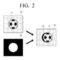
- FIG. 2 is a view illustrating a hole area generated when a target image is generated according to a DIBR method.
- a reference image 10 displaying at least one object 11 and depth information 20 are provided
- a position of the object 11 of the reference image 10 is shifted by using the depth information 20 to generate a target image 30.
- a hole area 12 is generated in a part of the target image 30 in which an original position of the object 11 and a new position do not overlap with each other.
- the controller 120 determines the stretching area, which is used to fill the hole area 12, from the back ground area by using a size of the hole area 12.
- FIG. 3 is a view illustrating a method of determining a stretching area.
- the hole area generated on the target image has a width in a horizontal direction.
- the controller 120 checks depth information corresponding to a boundary of the hole area to check whether a background area 14 of the object exists on the left side of the hole area or on the right side of the hole area.
- the controller 120 calculates energy values of pixels around the boundary of the hole area in the background area.
- the controller 120 calculates a width ⁇ of the hole area and pixels positioned within a distance of the width ⁇ in the background area. However, only pixels within the same distance are not necessarily selected, and pixels within a range of a distance longer than the width ⁇ may be selected.
- the controller 120 calculates energy values of the selected pixels.
- the energy values refer to characteristic values that are obtained through comparisons between pixels and peripheral pixels.
- the energy values may be defined as gradients of a color image.
- E x y ⁇ I x y
- E(x,y) denotes an energy value of a pixel positioned in (x,y)
- I(x,y) denotes a linear combination of R, G, and B components of the reference image.
- the controller 120 calculates an energy value by using one of Equations 3 through 5 below.
- E x y ⁇ ⁇ x ⁇ I x y + ⁇ ⁇ y ⁇ I x y
- E x y ⁇ ⁇ x ⁇ I x y 2 + ⁇ ⁇ y ⁇ I x y 2
- E x y ⁇ ⁇ x I x y 2 + ⁇ ⁇ y I x y 2
- the controller 120 calculates energy values of pixels of the background area by using these Equations. After that, the controller 120 sequentially checks the energy values of the pixels to detect pixels having energy values equal to or lower than a threshold value. The controller 120 combines the detected pixels to determine a stretching area 15.
- the controller 120 sequentially compares the energy values of the pixels with the threshold value from the boundary of the hole area 12 toward the background area. Therefore, if a pixel exceeding the threshold value is detected, the controller 120 determines an area ranging from a previous pixel to the boundary of the hole area 12 as the stretching area 15.
- the controller 120 performs an arithmetic operation in consideration of a difference between three color components.
- the controller 120 performs partial differentials of image components as follows.
- the threshold value may be determined as an average energy value.
- the controller 120 sets an average value of the energy values of the pixels within the distance of the width ⁇ from the boundary of the hole area in the background area, to the threshold value.
- a size of the stretching area is variably determined like 1 ⁇ ' ⁇ .
- the image processor 130 fills the pixels of the stretching area to complete the target image.
- FIG. 4 is a view illustrating a process of generating a target image by using a reference image and depth information.
- the image processing device 100 performs projection processing to generate a target image 30 including a hole area and a target depth map 40.
- the image processing device 100 also generates an energy map 50 of pixels of the reference image 10.
- the image processing device 100 determines a stretching area by using the energy map 50 and fills the hole area with pixels of the stretching area to generate a final target image 60.
- the depth information may be pre-processed and used by using a local maximum filter as in Equation below:
- D ⁇ x y max - s 2 ⁇ i ⁇ s 2 , - s 2 ⁇ j ⁇ s 2 D ⁇ x + i , y + j
- s denotes a window size
- D(x,y) denotes a depth of a pixel of x,y coordinates
- D ( x, y ) denotes a pre-processed depth. Since a maximum depth is filtered and used within a window of a particular size as described, sharpness of the depth information becomes higher.
- a value of the window size s may be an optimal value obtained through repeated tests. For example, 3 or 5 may be uses.
- the image processing device of FIG. 1 may be realized as various types of devices.
- the image processing device may be realized as a display apparatus such as a TV, a portable phone, a PDA, a PC, a notebook PC, a tablet PC, an e-frame, an e-book, or the like.
- the image processing device may be realized as a display apparatus such as a set-top box providing a 3D image, other image converting devices, a data player, or the like.
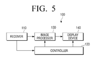
- FIG. 5 is a block diagram illustrating a structure of the image processing device 100 realized as a display apparatus.
- the image processing device 100 includes a receiver 110, a controller 120, an image processor 130, and a display device 140.
- the display device 140 combines a reference image and a target image to display a 3D image.
- the display device 140 may display the 3D image according to various methods according to exemplary embodiments.
- the display device 140 alternately arranges the reference image and the target image to sequentially the reference image and the target image.
- each of the reference image and the target image may be copied to be sequentially displayed as at least two or more frames.
- black frames may be filled and displayed.
- the image processing device 100 may transmit sync signal, which is to synchronize an eyeglass whenever each frame is displayed, to the eyeglass apparatus.
- the display device 140 may divide each of the reference image and the target image into a plurality of lines in a horizontal or vertical direction and combine odd and even lines of each of the reference image and the target image to generate and display at least one frame.
- FIG. 6 is a block diagram illustrating a structure of an image processing device connected to a display apparatus.
- the image processing device 100 includes a receiver 110, a controller, an image processor 130, and an interface 150.
- the interface 150 transmits a reference image and a target image to a display apparatus 200.
- the image processing device 100 is an apparatus separated from the display apparatus 100 in FIG. 6 but may be realized as a chip or module mounted in the display apparatus 200.
- FIGS. 5 and 6 except the display device 140 and the interface 150 are the same as those of FIG. 1 , and thus their repeated descriptions will be omitted.
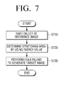
- FIG. 7 is a flowchart illustrating an image processing method according to an exemplary embodiment of the present general inventive concept.
- operation S710 an object included in a reference image is shifted by using depth information to generate a target image.
- a hole area is included in the target image formed in this operation.
- a shifted distance varies according to the depth information. In other words, a disparity of an object having a high depth value is great, and thus a shifted distance of the object becomes longer. A disparity of an object having a low depth value is small, and thus a shifted distance of the object is small.
- An energy value of the reference image is calculated separately from shifting of the object.
- a stretching area is determined from a background area around the hole area by using the calculated energy value.
- a hole-filling filling job for filling the hole area is performed by using pixels of the determined stretching area to complete the target image in operation S730.
- FIG. 8 is a flowchart illustrating a method of determining a stretching area according to an exemplary embodiment of the present general inventive concept.
- operation S810 a size of a hole size generated by shifting of an object is calculated. Since left and right eyes of a user are arranged side by side in a horizontal direction based on the surface of the earth, left and right eye images for forming a 3D image has a disparity in the horizontal direction. Therefore, a width of the hole area in the horizontal area is calculated and used.
- an energy value of a background area around the hole area is calculated in operation S820.
- an average value of the calculated energy values is calculated to set a threshold value .
- a whole part of the background area is not used, and only energy values of pixels in a part of the background area of a size corresponding to the width of the hole area may be used.
- the energy values of pixels of the background area are compared with the threshold value from a boundary of the hole area in operation S840. If the energy values are equal to or lower than the threshold value according to the comparison result, an energy value of a next pixel is checked and compared with the threshold value in operation S850. This operation is performed sequentially with respect to all pixels of the back ground area having the same size as the width of the hole area.
- a pixel value of the stretching area is inserted into the hole area to fill the hole area with the pixel value.
- the energy value is used, if a pattern is formed in the background area or a boundary of an adjacent object is formed in the background area, the hole area may be filled. Therefore, an image quality deterioration phenomenon may be prevented.
- smoothing processing may be performed with respect to the boundary of the hole area by using a smoothing filter.
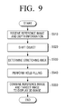
- FIG. 9 is a flowchart illustrating a method of displaying a 3D image according to an exemplary embodiment of the present general inventive concept.
- a display apparatus receives a reference image and depth information.
- the reference image and the depth information may be received from a content provider.
- the reference image and the depth information may be received in a transmission stream from a broadcasting station, a web server, or the like.
- the display apparatus performs processing, such as demodulating, equalizing, decoding, demultiplexing, etc., with respect to the received transmission stream to detect the reference image and the depth information.
- processing such as demodulating, equalizing, decoding, demultiplexing, etc.
- the display apparatus shifts an object of the reference image by using the depth information.
- the display apparatus calculates an energy value and compares the energy value with a threshold value to determine a stretching area.
- the display apparatus inserts a pixel of the stretching area into a hole area generated by shifting of the object to form a target image.
- the display apparatus combines the reference image and the target image to display a 3D image.
- the method of FIG. 9 may be performed by an image processing device or a display apparatus having the same structure as that described with reference to FIG. 5 . Detailed descriptions of operations of the method of FIG. 9 are the same as those described in the above exemplary embodiments and will be omitted.
- a target image having no image quality deterioration is generated from a reference image to display a 3D image.
- a program for executing methods according to the above-described exemplary embodiments of the present general inventive concept may be stored and used on various types of recording media.
- a code for performing the above-described methods may be stored on various types of computer-readable recording media such as a Random Access Memory (RAM), a flash memory, a Read Only Memory (ROM), an Erasable Programmable ROM (EPROM), an Electronically Erasable and Programmable ROM (EEPROM), a register, a hard disc, a removable disc, a memory card, a USB memory, a CD-ROM, etc.
- RAM Random Access Memory
- ROM Read Only Memory
- EPROM Erasable Programmable ROM
- EEPROM Electronically Erasable and Programmable ROM
Landscapes
- Engineering & Computer Science (AREA)
- Theoretical Computer Science (AREA)
- Physics & Mathematics (AREA)
- Computer Graphics (AREA)
- General Physics & Mathematics (AREA)
- Computing Systems (AREA)
- Geometry (AREA)
- Multimedia (AREA)
- Signal Processing (AREA)
- Testing, Inspecting, Measuring Of Stereoscopic Televisions And Televisions (AREA)
- Image Processing (AREA)
- Processing Or Creating Images (AREA)
Applications Claiming Priority (3)
| Application Number | Priority Date | Filing Date | Title |
|---|---|---|---|
| US41798710P | 2010-11-30 | 2010-11-30 | |
| KR1020110120489A KR20120059367A (ko) | 2010-11-30 | 2011-11-17 | 에너지값을 이용한 이미지 처리 장치와 그 이미지 처리 방법 및 디스플레이 방법 |
| PCT/KR2011/009221 WO2012074294A2 (fr) | 2010-11-30 | 2011-11-30 | Dispositif de traitement d'image utilisant une valeur d'énergie, et son procédé de traitement d'image et son procédé d'affichage |
Publications (2)
| Publication Number | Publication Date |
|---|---|
| EP2648162A2 true EP2648162A2 (fr) | 2013-10-09 |
| EP2648162A4 EP2648162A4 (fr) | 2014-08-06 |
Family
ID=46172400
Family Applications (1)
| Application Number | Title | Priority Date | Filing Date |
|---|---|---|---|
| EP11845396.8A Withdrawn EP2648162A4 (fr) | 2010-11-30 | 2011-11-30 | Dispositif de traitement d'image utilisant une valeur d'énergie, et son procédé de traitement d'image et son procédé d'affichage |
Country Status (6)
| Country | Link |
|---|---|
| US (1) | US20130286011A1 (fr) |
| EP (1) | EP2648162A4 (fr) |
| JP (1) | JP6025740B2 (fr) |
| KR (1) | KR20120059367A (fr) |
| CN (1) | CN103250185B (fr) |
| WO (1) | WO2012074294A2 (fr) |
Families Citing this family (3)
| Publication number | Priority date | Publication date | Assignee | Title |
|---|---|---|---|---|
| KR20140039649A (ko) * | 2012-09-24 | 2014-04-02 | 삼성전자주식회사 | 다시점 영상 생성 방법 및 다시점 영상 디스플레이 장치 |
| CN104378619B (zh) * | 2014-11-12 | 2016-09-28 | 合肥工业大学 | 一种基于前后景梯度过渡的快速高效的空洞填补算法 |
| WO2019194572A1 (fr) | 2018-04-03 | 2019-10-10 | Samsung Electronics Co., Ltd. | Procédés et appareil pour déterminer un paramètre de réglage pendant le codage d'un contenu multimédia sphérique |
Family Cites Families (16)
| Publication number | Priority date | Publication date | Assignee | Title |
|---|---|---|---|---|
| WO1997023097A2 (fr) * | 1995-12-19 | 1997-06-26 | Philips Electronics N.V. | Decalages parallactiques de pixels dependant de la profondeur |
| EP1257972B1 (fr) * | 2000-02-02 | 2006-12-06 | Quvis, Inc. | Systeme et procede permettant d'optimiser la resolution d'images au moyen de dispositifs d'imagerie pixelises |
| EP1437898A1 (fr) * | 2002-12-30 | 2004-07-14 | Koninklijke Philips Electronics N.V. | Filtrage vidéo pour des images steréo |
| EP1588327B1 (fr) * | 2003-01-17 | 2018-09-26 | Koninklijke Philips N.V. | Acquisition de carte de profondeur complète |
| TWI241127B (en) * | 2004-08-27 | 2005-10-01 | Univ Nat Cheng Kung | Image-capturing device and method for removing strangers |
| EP1958149B1 (fr) * | 2005-12-02 | 2012-01-18 | Koninklijke Philips Electronics N.V. | Procede et appareil d'affichage d'images stereoscopiques, procede de generation de donnees d'image 3d a partir d'une entree de donnees d'image 2d et appareil generant des donnees d'image 3d a partir d'une entree d'image 2d |
| WO2007096816A2 (fr) * | 2006-02-27 | 2007-08-30 | Koninklijke Philips Electronics N.V. | Rendu d'une image de sortie |
| JP5011319B2 (ja) * | 2006-02-28 | 2012-08-29 | コーニンクレッカ フィリップス エレクトロニクス エヌ ヴィ | 画像における指向性の穴埋め |
| US7573489B2 (en) * | 2006-06-01 | 2009-08-11 | Industrial Light & Magic | Infilling for 2D to 3D image conversion |
| EP1862969A1 (fr) * | 2006-06-02 | 2007-12-05 | Eidgenössische Technische Hochschule Zürich | Procédé et système de création de la représentation d'une scène 3D dynamiquement modifiée |
| EP2033164B1 (fr) * | 2006-06-23 | 2015-10-07 | Imax Corporation | Procédés et systèmes de conversion d'images cinématographiques 2d pour une représentation stéréoscopique 3d |
| US8330801B2 (en) * | 2006-12-22 | 2012-12-11 | Qualcomm Incorporated | Complexity-adaptive 2D-to-3D video sequence conversion |
| FR2917559B1 (fr) * | 2007-06-12 | 2009-12-25 | Centre Nat Rech Scient | Capteur d'images numeriques,procede d'acquisition et de reconstruction d'images,et systeme de mise en oeuvre |
| US8106924B2 (en) * | 2008-07-31 | 2012-01-31 | Stmicroelectronics S.R.L. | Method and system for video rendering, computer program product therefor |
| US8922628B2 (en) * | 2009-09-01 | 2014-12-30 | Prime Focus Vfx Services Ii Inc. | System and process for transforming two-dimensional images into three-dimensional images |
| JP5983935B2 (ja) * | 2011-11-30 | 2016-09-06 | パナソニックIpマネジメント株式会社 | 新視点画像生成装置および新視点画像生成方法 |
-
2011
- 2011-11-17 KR KR1020110120489A patent/KR20120059367A/ko not_active Ceased
- 2011-11-30 US US13/990,709 patent/US20130286011A1/en not_active Abandoned
- 2011-11-30 WO PCT/KR2011/009221 patent/WO2012074294A2/fr not_active Ceased
- 2011-11-30 CN CN201180057501.8A patent/CN103250185B/zh not_active Expired - Fee Related
- 2011-11-30 EP EP11845396.8A patent/EP2648162A4/fr not_active Withdrawn
- 2011-11-30 JP JP2013541923A patent/JP6025740B2/ja not_active Expired - Fee Related
Also Published As
| Publication number | Publication date |
|---|---|
| WO2012074294A2 (fr) | 2012-06-07 |
| WO2012074294A3 (fr) | 2012-07-26 |
| CN103250185A (zh) | 2013-08-14 |
| CN103250185B (zh) | 2017-03-15 |
| US20130286011A1 (en) | 2013-10-31 |
| JP6025740B2 (ja) | 2016-11-16 |
| KR20120059367A (ko) | 2012-06-08 |
| EP2648162A4 (fr) | 2014-08-06 |
| JP2013546281A (ja) | 2013-12-26 |
Similar Documents
| Publication | Publication Date | Title |
|---|---|---|
| US9135744B2 (en) | Method for filling hole-region and three-dimensional video system using the same | |
| US9460545B2 (en) | Apparatus and method for generating new viewpoint image | |
| CN101783967B (zh) | 信号处理设备、图像显示设备、信号处理方法和计算机程序 | |
| EP2175663B1 (fr) | Appareil de traitement des images | |
| CN103202026B (zh) | 图像转换设备及使用其的显示设备和方法 | |
| US20110193860A1 (en) | Method and Apparatus for Converting an Overlay Area into a 3D Image | |
| US9105133B2 (en) | Multi view image display apparatus and control method thereof | |
| KR100918007B1 (ko) | 3차원 모델의 스케일링 방법, 스케일링 유닛 및 화상디스플레이 장치 | |
| US20130051659A1 (en) | Stereoscopic image processing device and stereoscopic image processing method | |
| US9147281B2 (en) | Rendering apparatus and method for generating multi-views | |
| US20110249886A1 (en) | Image converting device and three-dimensional image display device including the same | |
| EP2753086A2 (fr) | Appareil d'affichage et son procédé d'affichage | |
| US20120274747A1 (en) | Stereoscopic video display device and stereoscopic video display method | |
| EP2490173B1 (fr) | Procédé de traitement d'une image stéréoscopique comportant une bande noire et dispositif correspondant | |
| CN102957929A (zh) | 视频信号处理设备、视频信号处理方法和计算机程序 | |
| EP2747428B1 (fr) | Procédé et appareil de rendu d'une image multi-vue | |
| US20140176539A1 (en) | Stereoscopic image processing apparatus, stereoscopic image processing method, and recording medium | |
| EP2648162A2 (fr) | Dispositif de traitement d'image utilisant une valeur d'énergie, et son procédé de traitement d'image et son procédé d'affichage | |
| US8976171B2 (en) | Depth estimation data generating apparatus, depth estimation data generating method, and depth estimation data generating program, and pseudo three-dimensional image generating apparatus, pseudo three-dimensional image generating method, and pseudo three-dimensional image generating program | |
| US20120170841A1 (en) | Image processing apparatus and method | |
| US20140092222A1 (en) | Stereoscopic image processing device, stereoscopic image processing method, and recording medium | |
| Hung et al. | Dual edge-confined inpainting of 3D depth map using color image's edges and depth image's edges | |
| EP2711894A2 (fr) | Dispositif de traitement d'images, procédé de traitement d'images et programme de traitement d'images | |
| EP2860975A1 (fr) | Procédé pour traiter au moins une carte de disparité, dispositif électronique correspondant et produit de programme informatique | |
| US9641821B2 (en) | Image signal processing device and image signal processing method |
Legal Events
| Date | Code | Title | Description |
|---|---|---|---|
| PUAI | Public reference made under article 153(3) epc to a published international application that has entered the european phase |
Free format text: ORIGINAL CODE: 0009012 |
|
| 17P | Request for examination filed |
Effective date: 20130430 |
|
| AK | Designated contracting states |
Kind code of ref document: A2 Designated state(s): AL AT BE BG CH CY CZ DE DK EE ES FI FR GB GR HR HU IE IS IT LI LT LU LV MC MK MT NL NO PL PT RO RS SE SI SK SM TR |
|
| DAX | Request for extension of the european patent (deleted) | ||
| A4 | Supplementary search report drawn up and despatched |
Effective date: 20140707 |
|
| RIC1 | Information provided on ipc code assigned before grant |
Ipc: G06T 15/00 20110101AFI20140701BHEP Ipc: H04N 13/00 20060101ALI20140701BHEP |
|
| 17Q | First examination report despatched |
Effective date: 20150609 |
|
| STAA | Information on the status of an ep patent application or granted ep patent |
Free format text: STATUS: EXAMINATION IS IN PROGRESS |
|
| STAA | Information on the status of an ep patent application or granted ep patent |
Free format text: STATUS: THE APPLICATION IS DEEMED TO BE WITHDRAWN |
|
| 18D | Application deemed to be withdrawn |
Effective date: 20170503 |