EP2648190A1 - Vorrichtung zum Erzeugen eines hohen Temperaturgradienten in einer Probe vom Typ Kernbrennstoff - Google Patents
Vorrichtung zum Erzeugen eines hohen Temperaturgradienten in einer Probe vom Typ Kernbrennstoff Download PDFInfo
- Publication number
- EP2648190A1 EP2648190A1 EP13161851.4A EP13161851A EP2648190A1 EP 2648190 A1 EP2648190 A1 EP 2648190A1 EP 13161851 A EP13161851 A EP 13161851A EP 2648190 A1 EP2648190 A1 EP 2648190A1
- Authority
- EP
- European Patent Office
- Prior art keywords
- assembly according
- sample
- fuel
- temperature
- resistor
- Prior art date
- Legal status (The legal status is an assumption and is not a legal conclusion. Google has not performed a legal analysis and makes no representation as to the accuracy of the status listed.)
- Granted
Links
- 239000003758 nuclear fuel Substances 0.000 title claims description 10
- 230000006698 induction Effects 0.000 claims abstract description 26
- 230000005672 electromagnetic field Effects 0.000 claims abstract description 8
- 239000008188 pellet Substances 0.000 claims description 38
- 239000000446 fuel Substances 0.000 claims description 31
- 238000009413 insulation Methods 0.000 claims description 16
- 239000000919 ceramic Substances 0.000 claims description 15
- 239000012212 insulator Substances 0.000 claims description 15
- 229910052751 metal Inorganic materials 0.000 claims description 8
- PNEYBMLMFCGWSK-UHFFFAOYSA-N aluminium oxide Inorganic materials [O-2].[O-2].[O-2].[Al+3].[Al+3] PNEYBMLMFCGWSK-UHFFFAOYSA-N 0.000 claims description 7
- 239000002184 metal Substances 0.000 claims description 7
- 239000010453 quartz Substances 0.000 claims description 6
- VYPSYNLAJGMNEJ-UHFFFAOYSA-N silicon dioxide Inorganic materials O=[Si]=O VYPSYNLAJGMNEJ-UHFFFAOYSA-N 0.000 claims description 6
- 229910018072 Al 2 O 3 Inorganic materials 0.000 claims description 4
- WFKWXMTUELFFGS-UHFFFAOYSA-N tungsten Chemical compound [W] WFKWXMTUELFFGS-UHFFFAOYSA-N 0.000 claims description 4
- 229910052721 tungsten Inorganic materials 0.000 claims description 4
- 239000010937 tungsten Substances 0.000 claims description 4
- 241000588731 Hafnia Species 0.000 claims description 3
- CJNBYAVZURUTKZ-UHFFFAOYSA-N hafnium(IV) oxide Inorganic materials O=[Hf]=O CJNBYAVZURUTKZ-UHFFFAOYSA-N 0.000 claims description 3
- ZOKXTWBITQBERF-UHFFFAOYSA-N Molybdenum Chemical compound [Mo] ZOKXTWBITQBERF-UHFFFAOYSA-N 0.000 claims description 2
- 239000012530 fluid Substances 0.000 claims description 2
- 229910052750 molybdenum Inorganic materials 0.000 claims description 2
- 239000011733 molybdenum Substances 0.000 claims description 2
- 239000003870 refractory metal Substances 0.000 claims description 2
- 238000010438 heat treatment Methods 0.000 description 17
- XLYOFNOQVPJJNP-UHFFFAOYSA-N water Substances O XLYOFNOQVPJJNP-UHFFFAOYSA-N 0.000 description 9
- MCMNRKCIXSYSNV-UHFFFAOYSA-N Zirconium dioxide Chemical compound O=[Zr]=O MCMNRKCIXSYSNV-UHFFFAOYSA-N 0.000 description 8
- 235000010603 pastilles Nutrition 0.000 description 8
- 230000000694 effects Effects 0.000 description 7
- 230000009466 transformation Effects 0.000 description 7
- 230000008878 coupling Effects 0.000 description 6
- 238000010168 coupling process Methods 0.000 description 6
- 238000005859 coupling reaction Methods 0.000 description 6
- 238000001816 cooling Methods 0.000 description 5
- 239000000463 material Substances 0.000 description 5
- HIGRAKVNKLCVCA-UHFFFAOYSA-N alumine Chemical compound C1=CC=[Al]C=C1 HIGRAKVNKLCVCA-UHFFFAOYSA-N 0.000 description 4
- 230000003993 interaction Effects 0.000 description 4
- FCTBKIHDJGHPPO-UHFFFAOYSA-N uranium dioxide Inorganic materials O=[U]=O FCTBKIHDJGHPPO-UHFFFAOYSA-N 0.000 description 4
- 229910052778 Plutonium Inorganic materials 0.000 description 3
- 238000005253 cladding Methods 0.000 description 3
- 230000001939 inductive effect Effects 0.000 description 3
- QCWXUUIWCKQGHC-UHFFFAOYSA-N Zirconium Chemical compound [Zr] QCWXUUIWCKQGHC-UHFFFAOYSA-N 0.000 description 2
- 229910001093 Zr alloy Inorganic materials 0.000 description 2
- 238000012442 analytical experiment Methods 0.000 description 2
- 230000004888 barrier function Effects 0.000 description 2
- 238000005485 electric heating Methods 0.000 description 2
- 230000004992 fission Effects 0.000 description 2
- 238000009434 installation Methods 0.000 description 2
- 238000005259 measurement Methods 0.000 description 2
- OYEHPCDNVJXUIW-UHFFFAOYSA-N plutonium atom Chemical compound [Pu] OYEHPCDNVJXUIW-UHFFFAOYSA-N 0.000 description 2
- 239000000126 substance Substances 0.000 description 2
- 238000012360 testing method Methods 0.000 description 2
- 238000012546 transfer Methods 0.000 description 2
- 229910052726 zirconium Inorganic materials 0.000 description 2
- KWGRBVOPPLSCSI-WPRPVWTQSA-N (-)-ephedrine Chemical compound CN[C@@H](C)[C@H](O)C1=CC=CC=C1 KWGRBVOPPLSCSI-WPRPVWTQSA-N 0.000 description 1
- 241000422252 Cales Species 0.000 description 1
- 229910052770 Uranium Inorganic materials 0.000 description 1
- 238000004364 calculation method Methods 0.000 description 1
- 238000002485 combustion reaction Methods 0.000 description 1
- 239000004020 conductor Substances 0.000 description 1
- 230000007797 corrosion Effects 0.000 description 1
- 238000005260 corrosion Methods 0.000 description 1
- 238000013461 design Methods 0.000 description 1
- 238000011161 development Methods 0.000 description 1
- 238000002474 experimental method Methods 0.000 description 1
- 239000011810 insulating material Substances 0.000 description 1
- 230000000155 isotopic effect Effects 0.000 description 1
- 230000007246 mechanism Effects 0.000 description 1
- 239000000203 mixture Substances 0.000 description 1
- OOAWCECZEHPMBX-UHFFFAOYSA-N oxygen(2-);uranium(4+) Chemical compound [O-2].[O-2].[U+4] OOAWCECZEHPMBX-UHFFFAOYSA-N 0.000 description 1
- UTDLAEPMVCFGRJ-UHFFFAOYSA-N plutonium dihydrate Chemical compound O.O.[Pu] UTDLAEPMVCFGRJ-UHFFFAOYSA-N 0.000 description 1
- FLDALJIYKQCYHH-UHFFFAOYSA-N plutonium(IV) oxide Inorganic materials [O-2].[O-2].[Pu+4] FLDALJIYKQCYHH-UHFFFAOYSA-N 0.000 description 1
- 230000000246 remedial effect Effects 0.000 description 1
- -1 sheath Substances 0.000 description 1
- 230000000930 thermomechanical effect Effects 0.000 description 1
- 230000001052 transient effect Effects 0.000 description 1
- JFALSRSLKYAFGM-UHFFFAOYSA-N uranium(0) Chemical compound [U] JFALSRSLKYAFGM-UHFFFAOYSA-N 0.000 description 1
- 238000010200 validation analysis Methods 0.000 description 1
Images


Classifications
-
- G—PHYSICS
- G21—NUCLEAR PHYSICS; NUCLEAR ENGINEERING
- G21C—NUCLEAR REACTORS
- G21C17/00—Monitoring; Testing ; Maintaining
- G21C17/10—Structural combination of fuel element, control rod, reactor core, or moderator structure with sensitive instruments, e.g. for measuring radioactivity, strain
- G21C17/112—Measuring temperature
-
- G—PHYSICS
- G21—NUCLEAR PHYSICS; NUCLEAR ENGINEERING
- G21C—NUCLEAR REACTORS
- G21C21/00—Apparatus or processes specially adapted to the manufacture of reactors or parts thereof
- G21C21/02—Manufacture of fuel elements or breeder elements contained in non-active casings
-
- G—PHYSICS
- G21—NUCLEAR PHYSICS; NUCLEAR ENGINEERING
- G21C—NUCLEAR REACTORS
- G21C17/00—Monitoring; Testing ; Maintaining
- G21C17/06—Devices or arrangements for monitoring or testing fuel or fuel elements outside the reactor core, e.g. for burn-up, for contamination
-
- G—PHYSICS
- G21—NUCLEAR PHYSICS; NUCLEAR ENGINEERING
- G21C—NUCLEAR REACTORS
- G21C3/00—Reactor fuel elements and their assemblies; Selection of substances for use as reactor fuel elements
- G21C3/02—Fuel elements
- G21C3/04—Constructional details
- G21C3/16—Details of the construction within the casing
- G21C3/20—Details of the construction within the casing with coating on fuel or on inside of casing; with non-active interlayer between casing and active material with multiple casings or multiple active layers
-
- Y—GENERAL TAGGING OF NEW TECHNOLOGICAL DEVELOPMENTS; GENERAL TAGGING OF CROSS-SECTIONAL TECHNOLOGIES SPANNING OVER SEVERAL SECTIONS OF THE IPC; TECHNICAL SUBJECTS COVERED BY FORMER USPC CROSS-REFERENCE ART COLLECTIONS [XRACs] AND DIGESTS
- Y02—TECHNOLOGIES OR APPLICATIONS FOR MITIGATION OR ADAPTATION AGAINST CLIMATE CHANGE
- Y02E—REDUCTION OF GREENHOUSE GAS [GHG] EMISSIONS, RELATED TO ENERGY GENERATION, TRANSMISSION OR DISTRIBUTION
- Y02E30/00—Energy generation of nuclear origin
- Y02E30/30—Nuclear fission reactors
Definitions
- the field of the invention is that of heating devices comprising the controlled generation of thermal gradient within a sample, particularly finding a particular interest for controlling and characterizing the behavior of nuclear fuels under a thermal gradient and which can be used in a high-temperature laboratory. nuclear activity.
- MOX fuel for "Oxide Mixes" containing plutonium dioxide PuO 2 and uranium dioxide UO 2 , made from about 7% plutonium and 93% depleted uranium, knowledge of the transfer phenomena of fission products, especially gaseous, within the fuel and loosening conditions, needs to be deepened.
- the fuels are in the form of UO 2 pellets or (U, Pu) O 2 stacked in a zirconium alloy sheath.
- UO 2 pellets or (U, Pu) O 2 stacked in a zirconium alloy sheath.
- IPG Interaction Pastille Sheath
- the fuel can undergo a large and rapid temperature increment compared to its normal situation. This thermal transient causes an increase in the stress of the pellet on the sheath and can lead to its rupture.
- the sheath is the first containment barrier to fission products, it is essential to ensure its integrity and therefore to better understand these IPG phenomena.
- DURANCE Device simulating the composition under thermal combustion of the Combustibles.
- This DURANCE device comprises a thermal gradient within the sample, provided by a heating chuck inserted in the core and a system of insulating materials cooled by an auxiliary device.
- the amplitude of the thermal gradient between the core of the sample and the outer face of the sheath is, therefore, driven by the core temperature level and the nature, thickness and external temperature of the insulators.
- the Applicant has sought to develop a device to reproduce and control the amplitude of the thermal gradient undergone by the nuclear fuel during certain accident situations and this thanks to a small-scale installation easily adaptable to the treatment furnaces thermal devices used by the laboratory in a high-activity cell and this by freeing itself from any water circulation (pressurized or not) in contact with the fuel element, the heating being provided by induction.
- the development of an induction heating system for two to three fuel pellets providing a heat flow from the inside to the outside of them makes it possible to represent the temperature profile observed in the reactor.
- One of the important objectives of the device proposed in the present invention is therefore to reproduce and control the amplitude of the thermal gradient undergone by a nuclear fuel during certain accident situations and this thanks to a reduced-size installation easily adaptable to heat treatment furnaces used by a laboratory in a high-activity cell and this by avoiding any circulation of water (pressurized or not) in contact with the fuel element, the heating being provided by induction.
- the device of the present invention constitutes in particular a solution that can make it possible to bring the fuel to a central temperature of up to 2000 ° C., or even more, and stabilize the sheath temperature at around 350 ° C. +/- 50 ° C. on typically three pellets of combustible.
- the first induction means comprise at least a first coil.
- the second means comprise at least one second coil.
- the enclosure is a quartz tube.
- the sample comprises a ceramic pellet may be Al 2 O 3 , or ZrO 2 or a nuclear fuel pellet may be UO 2 or MOX.
- the sample comprises a metal sheath on the periphery of said wafer and in direct contact with said wafer.
- it further comprises a thermal insulating element at the periphery of said sample.
- the sample comprises a ceramic pellet, the insulator being made of alumina.
- the sample comprises a ceramic pellet, the insulation being in hafnia.
- the sample comprises a fuel that can be in UO 2 , the insulation can be in UO 2 or hafnia.
- the resistance is made of refractory metal that can be tungsten or molybdenum.
- said assembly further comprises an exchanger, said second induction means being located at the periphery of said exchanger.
- the exchanger comprises a fluid circulation system.
- said assembly further comprises means for measuring the temperature of said sample.
- the means for measuring the temperature comprise a thermocouple.
- the invention also relates to an assembly according to the invention comprising a pyrometer.
- the invention also relates to an assembly according to the invention comprising an infrared camera.
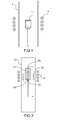
- the Applicant has developed a MERARG oven such as that illustrated in figure 1 for heating a metal crucible by inductive coupling.
- Induction coils 3 crossed by a high current Frequency can create currents induced in the metal crucible 1.
- these induced currents thus heat the walls of the crucible, which itself carries a sample at high temperature isothermally, the crucible being itself placed in a tube 2.
- induction heating can not be directly transcribed to the DURANCE device.
- susceptor corresponding to the part to be heated again called susceptor and in general, the susceptor must be an electrical conductor
- the zirconium alloy sheath metal element
- the sheath would be heated in the same way as the crucible in MERARG.
- first induction means that can be an induction coil for heating the central resistive system
- the solution proposed in the present invention adapts the principle of an electrical transformer.
- first induction means which can be a turn (coil) called transformation.
- This turn then creates a so-called induced current that flows in the resistance.
- This turn is placed inside the quartz tube and centered at the level of the induction coil.
- This device makes it possible to keep the same power supply system. It also makes it possible to preserve the quartz tube which guarantees the tightness of the oven and which, by its physico-chemical properties, does not interact with the coupling phenomenon.
- the figure 2 thus illustrates a device of the invention comprising in an enclosure 20, a resistor 60, a first induction coil 31 and a second so-called transformation turn 32.
- the sample to be heated 100 is surrounded by a not shown sheath and of an insulator 101 and is traversed by the resistor 60 at its center.
- a thermocouple 61 is also provided for the measurement of temperature.
- the device of the present invention thus makes it possible to heat inductively by coupling a metal element, and then by resistive heating of the resistor 60, to heat the inside of the pellets.
- This assembly makes it possible to keep the same power supply system. It allows also to keep for example a quartz tube that ensures the tightness of the oven and, by its physicochemical properties, does not interact on the coupling phenomenon.
- the DURANCE device seeks to apply a known and predetermined radial thermal gradient within an irradiated nuclear ceramic.
- the Applicant has modeled under Cast3m the thermal behavior of the device of the invention. This modeling allowed, as a first step, and through a parametric study as simple as possible, to confirm the presence of a radial gradient within the pellets and to specify the nature and the geometry of the insulators to obtain the gradient desired thermal.
- This analysis details the assumptions made to obtain a simplified model of DURANCE (definition of the geometric model, definition of the thermal model, ). The results obtained were confronted with the desired objectives to conclude on the validity of the concept.
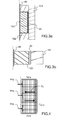
- the cooling circuit is modeled by a temperature imposed at 20 ° C corresponding to the temperature of the water circulating in the exchanger as illustrated in figure 4 which shows, according to the thermal model, the injected power density P inj and the near-perfect conduction Cp between the different materials (pellet, sheath, insulator), between two adiabatic A dia .
- the modeling shows that in order to obtain a temperature at the outer wall of the sheath of 350 ° C., the insulator to be used is dense alumina with a thickness of 4 to 5 mm. .
- the thickness of this insulation is to be determined according to the temperatures at the center of the pellets.
- the choice of insulation is dense Hafnie between 3 and 5 mm thick depending on center temperatures pellets referred.
- the modeling shows the use of an insulator either in UO 2 or in Hafnie between 3 and 5 mm thickness depending the central temperature for a sheath temperature of 350 ° C.
- the assembly thus formed can be integrated into a quartz tube constituting an evolution of the MERARG II oven.
- the induction coil then couples on the turn of transformation, it is short-circuited by the tungsten resistance, passing through the wedges and fuel pellets.
- the turn of transformation, the induction coil and the exchanger are in turn cooled by water.
- thermocouple is mounted in contact with the resistor to observe its behavior during power up of the device.
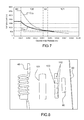
- the figure 9 illustrates, the temperature cycles applied at the level of the resistance. Three different ramps were applied and four trays in temperature (1000 ° C., 1300 ° C., 1600 ° C. and 2000 ° C.) were maintained between the ramps R 1 , R 2 and R 3 , the curve C 9 being relative to the temperature of the susceptor.
- the temperature of the resistor is voluntarily limited to a temperature of 2000 ° C over a very short time.
Landscapes
- Engineering & Computer Science (AREA)
- Physics & Mathematics (AREA)
- Plasma & Fusion (AREA)
- General Engineering & Computer Science (AREA)
- High Energy & Nuclear Physics (AREA)
- Manufacturing & Machinery (AREA)
- Monitoring And Testing Of Nuclear Reactors (AREA)
Applications Claiming Priority (1)
| Application Number | Priority Date | Filing Date | Title |
|---|---|---|---|
| FR1253001A FR2988974B1 (fr) | 2012-04-02 | 2012-04-02 | Dispositif pour generer un gradient eleve de temperature dans un echantillon de type combustible nucleaire |
Publications (2)
| Publication Number | Publication Date |
|---|---|
| EP2648190A1 true EP2648190A1 (de) | 2013-10-09 |
| EP2648190B1 EP2648190B1 (de) | 2017-03-01 |
Family
ID=46754555
Family Applications (1)
| Application Number | Title | Priority Date | Filing Date |
|---|---|---|---|
| EP13161851.4A Not-in-force EP2648190B1 (de) | 2012-04-02 | 2013-03-29 | Vorrichtung zum Erzeugen eines hohen Temperaturgradienten in einer Probe vom Typ Kernbrennstoff |
Country Status (7)
| Country | Link |
|---|---|
| US (1) | US20130259181A1 (de) |
| EP (1) | EP2648190B1 (de) |
| JP (1) | JP2013213821A (de) |
| KR (1) | KR20130112011A (de) |
| CN (1) | CN103366840A (de) |
| FR (1) | FR2988974B1 (de) |
| RU (1) | RU2013114461A (de) |
Families Citing this family (5)
| Publication number | Priority date | Publication date | Assignee | Title |
|---|---|---|---|---|
| FR2975527B1 (fr) * | 2011-05-18 | 2013-07-05 | Commissariat Energie Atomique | Dispositif de chauffage electrique d'un liquide, son procede de realisation et application a la simulation electrique de crayons de combustible nucleaire |
| FR3011711B1 (fr) * | 2013-10-03 | 2015-12-11 | Commissariat Energie Atomique | Dispositif pour generer un gradient eleve de temperature dans un echantillon de type combustible nucleaire |
| JP6516659B2 (ja) * | 2015-11-24 | 2019-05-22 | 三菱重工業株式会社 | 模擬ペレット、模擬燃料棒、及び模擬燃料集合体 |
| US12288320B2 (en) * | 2020-12-22 | 2025-04-29 | University Of South Carolina | Experimental set up for studying temperature gradient driven cracking |
| CN118737505A (zh) * | 2024-06-13 | 2024-10-01 | 四川大学 | 可用于薄壁短管高温高热流密度测试的实验装置 |
Citations (7)
| Publication number | Priority date | Publication date | Assignee | Title |
|---|---|---|---|---|
| JPS495689B1 (de) * | 1966-10-24 | 1974-02-08 | ||
| FR2582896A1 (fr) * | 1985-06-04 | 1986-12-05 | Cableco Sa | Appareils electrodomestiques ou analogues utilisables avec les foyers a induction et ne necessitant pas de branchement pour leur alimentation. |
| US4643866A (en) | 1983-08-24 | 1987-02-17 | The Babcock & Wilcox Company | Nuclear fuel pellet-cladding interaction test device and method modeling in-core reactor thermal conditions |
| US20060283849A1 (en) * | 2005-06-16 | 2006-12-21 | Ngk Spark Plug Co. Ltd. | Ceramic-metal assembly and ceramic heater |
| US20080023141A1 (en) * | 2006-07-26 | 2008-01-31 | Hitachi Kokusai Electric Inc. | Substrate processing apparatus |
| FR2931580A1 (fr) * | 2008-05-21 | 2009-11-27 | Westinghouse Electric Corp | Mesure de la pression interne de crayons combustibles |
| US20110176650A1 (en) * | 2008-09-30 | 2011-07-21 | Areva Np | Nuclear reactor green and sintered fuel pellets, corresponding fuel rod and fuel assembly |
Family Cites Families (7)
| Publication number | Priority date | Publication date | Assignee | Title |
|---|---|---|---|---|
| NL234527A (de) * | 1958-12-22 | |||
| GB1136616A (en) * | 1965-12-01 | 1968-12-11 | Aeg Elotherm Gmbh | A method of and apparatus for inductively heating electrically conducting workpieces |
| BE744908A (fr) * | 1969-02-01 | 1970-07-01 | Euratom | Appareil pour l'etude de l'evolution de la structure de carbured'uranium soumis a un gradient thermique radial |
| JPS57142525A (en) * | 1981-02-27 | 1982-09-03 | Toshiba Corp | Measuring method for output distribution of heater |
| JPS5957196A (ja) * | 1982-09-28 | 1984-04-02 | 株式会社東芝 | 核燃料棒の発熱模擬供試体 |
| FR2646049B1 (fr) * | 1989-04-18 | 1991-05-24 | Cableco Sa | Plaque electrique chauffante amovible |
| US5084229A (en) * | 1990-05-31 | 1992-01-28 | The United States Of America As Represented By The United States Department Of Energy | Critical heat flux test apparatus |
-
2012
- 2012-04-02 FR FR1253001A patent/FR2988974B1/fr active Active
-
2013
- 2013-03-29 EP EP13161851.4A patent/EP2648190B1/de not_active Not-in-force
- 2013-04-01 RU RU2013114461/07A patent/RU2013114461A/ru not_active Application Discontinuation
- 2013-04-02 US US13/855,615 patent/US20130259181A1/en not_active Abandoned
- 2013-04-02 JP JP2013076952A patent/JP2013213821A/ja active Pending
- 2013-04-02 CN CN2013101658273A patent/CN103366840A/zh active Pending
- 2013-04-02 KR KR1020130036001A patent/KR20130112011A/ko not_active Withdrawn
Patent Citations (7)
| Publication number | Priority date | Publication date | Assignee | Title |
|---|---|---|---|---|
| JPS495689B1 (de) * | 1966-10-24 | 1974-02-08 | ||
| US4643866A (en) | 1983-08-24 | 1987-02-17 | The Babcock & Wilcox Company | Nuclear fuel pellet-cladding interaction test device and method modeling in-core reactor thermal conditions |
| FR2582896A1 (fr) * | 1985-06-04 | 1986-12-05 | Cableco Sa | Appareils electrodomestiques ou analogues utilisables avec les foyers a induction et ne necessitant pas de branchement pour leur alimentation. |
| US20060283849A1 (en) * | 2005-06-16 | 2006-12-21 | Ngk Spark Plug Co. Ltd. | Ceramic-metal assembly and ceramic heater |
| US20080023141A1 (en) * | 2006-07-26 | 2008-01-31 | Hitachi Kokusai Electric Inc. | Substrate processing apparatus |
| FR2931580A1 (fr) * | 2008-05-21 | 2009-11-27 | Westinghouse Electric Corp | Mesure de la pression interne de crayons combustibles |
| US20110176650A1 (en) * | 2008-09-30 | 2011-07-21 | Areva Np | Nuclear reactor green and sintered fuel pellets, corresponding fuel rod and fuel assembly |
Non-Patent Citations (1)
| Title |
|---|
| J.F. WHATHAM, NUCLEAR ENGINEERING AND DESIGN, vol. 26, 1974, pages 423 - 431 |
Also Published As
| Publication number | Publication date |
|---|---|
| KR20130112011A (ko) | 2013-10-11 |
| CN103366840A (zh) | 2013-10-23 |
| EP2648190B1 (de) | 2017-03-01 |
| US20130259181A1 (en) | 2013-10-03 |
| FR2988974B1 (fr) | 2017-09-01 |
| FR2988974A1 (fr) | 2013-10-04 |
| RU2013114461A (ru) | 2014-10-10 |
| JP2013213821A (ja) | 2013-10-17 |
Similar Documents
| Publication | Publication Date | Title |
|---|---|---|
| EP2648190B1 (de) | Vorrichtung zum Erzeugen eines hohen Temperaturgradienten in einer Probe vom Typ Kernbrennstoff | |
| EP2858072B1 (de) | Vorrichtung mit optischen Kontrollmitteln zur Erzeugung eines hohen Temperaturgradienten in einer Probe | |
| Stuckert et al. | Experimental results of the QUENCH-16 bundle test on air ingress | |
| Su et al. | Wettability and CHF limits of Accident-Tolerant nuclear fuel cladding materials in light water reactor conditions | |
| Bianco et al. | Experimental investigation on the causes for pellet fragmentation under LOCA conditions | |
| Seong et al. | Separate effect of oxidation on the subcooled flow boiling performance of Zircaloy-4 at atmospheric pressure | |
| Kossolapov | Transient flow boiling CHF under exponentially escalating heat inputs | |
| Jung et al. | Quenching behavior of high temperature Cr-coated Zr-alloy cladding during bottom reflood condition | |
| Wang et al. | Thermal conductivity measurements for simulated PWR crud | |
| Zeng et al. | A scoping study on remelting process of a debris bed in the lower head of reactor pressure vessel | |
| Villard et al. | Improving high-temperature measurements in nuclear reactors with Mo/Nb thermocouples | |
| Singh et al. | Effects of elevated temperature steam oxidation and subsequent quenching on light water reactor clad | |
| Spencer et al. | Separate-effects validation experiments for models of fracture in ceramic nuclear fuel | |
| Schulthess et al. | Experimental results of conductive inserts to reduce nuclear fuel temperature during nuclear volumetric heating | |
| Fudurich | Effect of liquid subcooling, initial surface temperature, and surface properties on the minimum film boiling temperature | |
| Singh et al. | Experimental study on thermally assisted sagging deflection and interaction of multiple coolant channels | |
| Yamato et al. | Reduction in the onset time of breakaway oxidation on Zircaloy cladding ruptured under simulated LOCA conditions | |
| Ferry et al. | The LORELEI test device for LOCA experiments in the Jules Horowitz reactor | |
| Condie et al. | Design and evaluation of an enhanced in-vessel core catcher | |
| Kam et al. | Fast transient heat transfer by sinusoidal pulse power | |
| Byun et al. | METHOD FOR EXPOSING IRRADIATED FUEL CLADDING TO RAPID THERMAL TRANSIENTS | |
| Dehaudt et al. | Composite fuel behaviour under and after irradiation | |
| Rempe | In-vessel retention-recent efforts and future needs | |
| Kruglov et al. | Thermal contact resistance of a liquid lead and structural steel | |
| Rempe | Design and Evaluation of an Enhanced In-Vessel Core Catcher |
Legal Events
| Date | Code | Title | Description |
|---|---|---|---|
| PUAI | Public reference made under article 153(3) epc to a published international application that has entered the european phase |
Free format text: ORIGINAL CODE: 0009012 |
|
| AK | Designated contracting states |
Kind code of ref document: A1 Designated state(s): AL AT BE BG CH CY CZ DE DK EE ES FI FR GB GR HR HU IE IS IT LI LT LU LV MC MK MT NL NO PL PT RO RS SE SI SK SM TR |
|
| AX | Request for extension of the european patent |
Extension state: BA ME |
|
| 17P | Request for examination filed |
Effective date: 20140312 |
|
| RBV | Designated contracting states (corrected) |
Designated state(s): AL AT BE BG CH CY CZ DE DK EE ES FI FR GB GR HR HU IE IS IT LI LT LU LV MC MK MT NL NO PL PT RO RS SE SI SK SM TR |
|
| GRAP | Despatch of communication of intention to grant a patent |
Free format text: ORIGINAL CODE: EPIDOSNIGR1 |
|
| INTG | Intention to grant announced |
Effective date: 20160929 |
|
| STAA | Information on the status of an ep patent application or granted ep patent |
Free format text: STATUS: GRANT OF PATENT IS INTENDED |
|
| GRAS | Grant fee paid |
Free format text: ORIGINAL CODE: EPIDOSNIGR3 |
|
| GRAA | (expected) grant |
Free format text: ORIGINAL CODE: 0009210 |
|
| STAA | Information on the status of an ep patent application or granted ep patent |
Free format text: STATUS: THE PATENT HAS BEEN GRANTED |
|
| AK | Designated contracting states |
Kind code of ref document: B1 Designated state(s): AL AT BE BG CH CY CZ DE DK EE ES FI FR GB GR HR HU IE IS IT LI LT LU LV MC MK MT NL NO PL PT RO RS SE SI SK SM TR |
|
| REG | Reference to a national code |
Ref country code: GB Ref legal event code: FG4D Free format text: NOT ENGLISH |
|
| REG | Reference to a national code |
Ref country code: CH Ref legal event code: EP Ref country code: AT Ref legal event code: REF Ref document number: 872181 Country of ref document: AT Kind code of ref document: T Effective date: 20170315 |
|
| REG | Reference to a national code |
Ref country code: IE Ref legal event code: FG4D Free format text: LANGUAGE OF EP DOCUMENT: FRENCH |
|
| REG | Reference to a national code |
Ref country code: FR Ref legal event code: PLFP Year of fee payment: 5 |
|
| REG | Reference to a national code |
Ref country code: DE Ref legal event code: R096 Ref document number: 602013017849 Country of ref document: DE |
|
| REG | Reference to a national code |
Ref country code: SE Ref legal event code: TRGR |
|
| REG | Reference to a national code |
Ref country code: NL Ref legal event code: MP Effective date: 20170301 |
|
| REG | Reference to a national code |
Ref country code: LT Ref legal event code: MG4D |
|
| REG | Reference to a national code |
Ref country code: AT Ref legal event code: MK05 Ref document number: 872181 Country of ref document: AT Kind code of ref document: T Effective date: 20170301 |
|
| PG25 | Lapsed in a contracting state [announced via postgrant information from national office to epo] |
Ref country code: NO Free format text: LAPSE BECAUSE OF FAILURE TO SUBMIT A TRANSLATION OF THE DESCRIPTION OR TO PAY THE FEE WITHIN THE PRESCRIBED TIME-LIMIT Effective date: 20170601 Ref country code: LT Free format text: LAPSE BECAUSE OF FAILURE TO SUBMIT A TRANSLATION OF THE DESCRIPTION OR TO PAY THE FEE WITHIN THE PRESCRIBED TIME-LIMIT Effective date: 20170301 Ref country code: HR Free format text: LAPSE BECAUSE OF FAILURE TO SUBMIT A TRANSLATION OF THE DESCRIPTION OR TO PAY THE FEE WITHIN THE PRESCRIBED TIME-LIMIT Effective date: 20170301 Ref country code: FI Free format text: LAPSE BECAUSE OF FAILURE TO SUBMIT A TRANSLATION OF THE DESCRIPTION OR TO PAY THE FEE WITHIN THE PRESCRIBED TIME-LIMIT Effective date: 20170301 |
|
| PG25 | Lapsed in a contracting state [announced via postgrant information from national office to epo] |
Ref country code: LV Free format text: LAPSE BECAUSE OF FAILURE TO SUBMIT A TRANSLATION OF THE DESCRIPTION OR TO PAY THE FEE WITHIN THE PRESCRIBED TIME-LIMIT Effective date: 20170301 Ref country code: RS Free format text: LAPSE BECAUSE OF FAILURE TO SUBMIT A TRANSLATION OF THE DESCRIPTION OR TO PAY THE FEE WITHIN THE PRESCRIBED TIME-LIMIT Effective date: 20170301 Ref country code: BG Free format text: LAPSE BECAUSE OF FAILURE TO SUBMIT A TRANSLATION OF THE DESCRIPTION OR TO PAY THE FEE WITHIN THE PRESCRIBED TIME-LIMIT Effective date: 20170601 Ref country code: ES Free format text: LAPSE BECAUSE OF FAILURE TO SUBMIT A TRANSLATION OF THE DESCRIPTION OR TO PAY THE FEE WITHIN THE PRESCRIBED TIME-LIMIT Effective date: 20170301 Ref country code: AT Free format text: LAPSE BECAUSE OF FAILURE TO SUBMIT A TRANSLATION OF THE DESCRIPTION OR TO PAY THE FEE WITHIN THE PRESCRIBED TIME-LIMIT Effective date: 20170301 |
|
| PG25 | Lapsed in a contracting state [announced via postgrant information from national office to epo] |
Ref country code: NL Free format text: LAPSE BECAUSE OF FAILURE TO SUBMIT A TRANSLATION OF THE DESCRIPTION OR TO PAY THE FEE WITHIN THE PRESCRIBED TIME-LIMIT Effective date: 20170301 |
|
| PG25 | Lapsed in a contracting state [announced via postgrant information from national office to epo] |
Ref country code: SK Free format text: LAPSE BECAUSE OF FAILURE TO SUBMIT A TRANSLATION OF THE DESCRIPTION OR TO PAY THE FEE WITHIN THE PRESCRIBED TIME-LIMIT Effective date: 20170301 Ref country code: CZ Free format text: LAPSE BECAUSE OF FAILURE TO SUBMIT A TRANSLATION OF THE DESCRIPTION OR TO PAY THE FEE WITHIN THE PRESCRIBED TIME-LIMIT Effective date: 20170301 Ref country code: IT Free format text: LAPSE BECAUSE OF FAILURE TO SUBMIT A TRANSLATION OF THE DESCRIPTION OR TO PAY THE FEE WITHIN THE PRESCRIBED TIME-LIMIT Effective date: 20170301 Ref country code: EE Free format text: LAPSE BECAUSE OF FAILURE TO SUBMIT A TRANSLATION OF THE DESCRIPTION OR TO PAY THE FEE WITHIN THE PRESCRIBED TIME-LIMIT Effective date: 20170301 Ref country code: RO Free format text: LAPSE BECAUSE OF FAILURE TO SUBMIT A TRANSLATION OF THE DESCRIPTION OR TO PAY THE FEE WITHIN THE PRESCRIBED TIME-LIMIT Effective date: 20170301 |
|
| REG | Reference to a national code |
Ref country code: CH Ref legal event code: PL |
|
| PG25 | Lapsed in a contracting state [announced via postgrant information from national office to epo] |
Ref country code: SM Free format text: LAPSE BECAUSE OF FAILURE TO SUBMIT A TRANSLATION OF THE DESCRIPTION OR TO PAY THE FEE WITHIN THE PRESCRIBED TIME-LIMIT Effective date: 20170301 Ref country code: PT Free format text: LAPSE BECAUSE OF FAILURE TO SUBMIT A TRANSLATION OF THE DESCRIPTION OR TO PAY THE FEE WITHIN THE PRESCRIBED TIME-LIMIT Effective date: 20170703 Ref country code: IS Free format text: LAPSE BECAUSE OF FAILURE TO SUBMIT A TRANSLATION OF THE DESCRIPTION OR TO PAY THE FEE WITHIN THE PRESCRIBED TIME-LIMIT Effective date: 20170701 Ref country code: PL Free format text: LAPSE BECAUSE OF FAILURE TO SUBMIT A TRANSLATION OF THE DESCRIPTION OR TO PAY THE FEE WITHIN THE PRESCRIBED TIME-LIMIT Effective date: 20170301 |
|
| REG | Reference to a national code |
Ref country code: DE Ref legal event code: R097 Ref document number: 602013017849 Country of ref document: DE |
|
| REG | Reference to a national code |
Ref country code: IE Ref legal event code: MM4A |
|
| PLBE | No opposition filed within time limit |
Free format text: ORIGINAL CODE: 0009261 |
|
| STAA | Information on the status of an ep patent application or granted ep patent |
Free format text: STATUS: NO OPPOSITION FILED WITHIN TIME LIMIT |
|
| PG25 | Lapsed in a contracting state [announced via postgrant information from national office to epo] |
Ref country code: MC Free format text: LAPSE BECAUSE OF FAILURE TO SUBMIT A TRANSLATION OF THE DESCRIPTION OR TO PAY THE FEE WITHIN THE PRESCRIBED TIME-LIMIT Effective date: 20170301 Ref country code: DK Free format text: LAPSE BECAUSE OF FAILURE TO SUBMIT A TRANSLATION OF THE DESCRIPTION OR TO PAY THE FEE WITHIN THE PRESCRIBED TIME-LIMIT Effective date: 20170301 Ref country code: LU Free format text: LAPSE BECAUSE OF NON-PAYMENT OF DUE FEES Effective date: 20170329 |
|
| 26N | No opposition filed |
Effective date: 20171204 |
|
| PG25 | Lapsed in a contracting state [announced via postgrant information from national office to epo] |
Ref country code: SI Free format text: LAPSE BECAUSE OF FAILURE TO SUBMIT A TRANSLATION OF THE DESCRIPTION OR TO PAY THE FEE WITHIN THE PRESCRIBED TIME-LIMIT Effective date: 20170301 Ref country code: IE Free format text: LAPSE BECAUSE OF NON-PAYMENT OF DUE FEES Effective date: 20170329 Ref country code: CH Free format text: LAPSE BECAUSE OF NON-PAYMENT OF DUE FEES Effective date: 20170331 Ref country code: LI Free format text: LAPSE BECAUSE OF NON-PAYMENT OF DUE FEES Effective date: 20170331 |
|
| REG | Reference to a national code |
Ref country code: FR Ref legal event code: PLFP Year of fee payment: 6 |
|
| PG25 | Lapsed in a contracting state [announced via postgrant information from national office to epo] |
Ref country code: MT Free format text: LAPSE BECAUSE OF FAILURE TO SUBMIT A TRANSLATION OF THE DESCRIPTION OR TO PAY THE FEE WITHIN THE PRESCRIBED TIME-LIMIT Effective date: 20170301 |
|
| PG25 | Lapsed in a contracting state [announced via postgrant information from national office to epo] |
Ref country code: HU Free format text: LAPSE BECAUSE OF FAILURE TO SUBMIT A TRANSLATION OF THE DESCRIPTION OR TO PAY THE FEE WITHIN THE PRESCRIBED TIME-LIMIT; INVALID AB INITIO Effective date: 20130329 |
|
| PG25 | Lapsed in a contracting state [announced via postgrant information from national office to epo] |
Ref country code: CY Free format text: LAPSE BECAUSE OF NON-PAYMENT OF DUE FEES Effective date: 20170301 |
|
| PG25 | Lapsed in a contracting state [announced via postgrant information from national office to epo] |
Ref country code: MK Free format text: LAPSE BECAUSE OF FAILURE TO SUBMIT A TRANSLATION OF THE DESCRIPTION OR TO PAY THE FEE WITHIN THE PRESCRIBED TIME-LIMIT Effective date: 20170301 |
|
| PG25 | Lapsed in a contracting state [announced via postgrant information from national office to epo] |
Ref country code: TR Free format text: LAPSE BECAUSE OF FAILURE TO SUBMIT A TRANSLATION OF THE DESCRIPTION OR TO PAY THE FEE WITHIN THE PRESCRIBED TIME-LIMIT Effective date: 20170301 |
|
| PGFP | Annual fee paid to national office [announced via postgrant information from national office to epo] |
Ref country code: SE Payment date: 20200327 Year of fee payment: 8 Ref country code: GB Payment date: 20200323 Year of fee payment: 8 Ref country code: DE Payment date: 20200311 Year of fee payment: 8 |
|
| PGFP | Annual fee paid to national office [announced via postgrant information from national office to epo] |
Ref country code: BE Payment date: 20200330 Year of fee payment: 8 |
|
| PG25 | Lapsed in a contracting state [announced via postgrant information from national office to epo] |
Ref country code: GR Free format text: LAPSE BECAUSE OF FAILURE TO SUBMIT A TRANSLATION OF THE DESCRIPTION OR TO PAY THE FEE WITHIN THE PRESCRIBED TIME-LIMIT Effective date: 20170301 |
|
| PG25 | Lapsed in a contracting state [announced via postgrant information from national office to epo] |
Ref country code: AL Free format text: LAPSE BECAUSE OF FAILURE TO SUBMIT A TRANSLATION OF THE DESCRIPTION OR TO PAY THE FEE WITHIN THE PRESCRIBED TIME-LIMIT Effective date: 20170301 |
|
| PGFP | Annual fee paid to national office [announced via postgrant information from national office to epo] |
Ref country code: FR Payment date: 20200331 Year of fee payment: 8 |
|
| REG | Reference to a national code |
Ref country code: DE Ref legal event code: R119 Ref document number: 602013017849 Country of ref document: DE |
|
| GBPC | Gb: european patent ceased through non-payment of renewal fee |
Effective date: 20210329 |
|
| REG | Reference to a national code |
Ref country code: BE Ref legal event code: MM Effective date: 20210331 |
|
| PG25 | Lapsed in a contracting state [announced via postgrant information from national office to epo] |
Ref country code: FR Free format text: LAPSE BECAUSE OF NON-PAYMENT OF DUE FEES Effective date: 20210331 Ref country code: GB Free format text: LAPSE BECAUSE OF NON-PAYMENT OF DUE FEES Effective date: 20210329 Ref country code: DE Free format text: LAPSE BECAUSE OF NON-PAYMENT OF DUE FEES Effective date: 20211001 Ref country code: SE Free format text: LAPSE BECAUSE OF NON-PAYMENT OF DUE FEES Effective date: 20210330 |
|
| PG25 | Lapsed in a contracting state [announced via postgrant information from national office to epo] |
Ref country code: BE Free format text: LAPSE BECAUSE OF NON-PAYMENT OF DUE FEES Effective date: 20210331 |