EP2648249B1 - Matériau actif négatif, batterie au lithium comprenant ce matériau et procédé de fabrication du matériau - Google Patents
Matériau actif négatif, batterie au lithium comprenant ce matériau et procédé de fabrication du matériau Download PDFInfo
- Publication number
- EP2648249B1 EP2648249B1 EP13162609.5A EP13162609A EP2648249B1 EP 2648249 B1 EP2648249 B1 EP 2648249B1 EP 13162609 A EP13162609 A EP 13162609A EP 2648249 B1 EP2648249 B1 EP 2648249B1
- Authority
- EP
- European Patent Office
- Prior art keywords
- silicon
- active material
- alloy
- negative active
- range
- Prior art date
- Legal status (The legal status is an assumption and is not a legal conclusion. Google has not performed a legal analysis and makes no representation as to the accuracy of the status listed.)
- Active
Links
Images




Classifications
-
- H—ELECTRICITY
- H01—ELECTRIC ELEMENTS
- H01M—PROCESSES OR MEANS, e.g. BATTERIES, FOR THE DIRECT CONVERSION OF CHEMICAL ENERGY INTO ELECTRICAL ENERGY
- H01M4/00—Electrodes
- H01M4/02—Electrodes composed of, or comprising, active material
- H01M4/36—Selection of substances as active materials, active masses, active liquids
- H01M4/38—Selection of substances as active materials, active masses, active liquids of elements or alloys
- H01M4/386—Silicon or alloys based on silicon
-
- H—ELECTRICITY
- H01—ELECTRIC ELEMENTS
- H01M—PROCESSES OR MEANS, e.g. BATTERIES, FOR THE DIRECT CONVERSION OF CHEMICAL ENERGY INTO ELECTRICAL ENERGY
- H01M10/00—Secondary cells; Manufacture thereof
- H01M10/05—Accumulators with non-aqueous electrolyte
- H01M10/052—Li-accumulators
-
- H—ELECTRICITY
- H01—ELECTRIC ELEMENTS
- H01M—PROCESSES OR MEANS, e.g. BATTERIES, FOR THE DIRECT CONVERSION OF CHEMICAL ENERGY INTO ELECTRICAL ENERGY
- H01M10/00—Secondary cells; Manufacture thereof
- H01M10/05—Accumulators with non-aqueous electrolyte
- H01M10/052—Li-accumulators
- H01M10/0525—Rocking-chair batteries, i.e. batteries with lithium insertion or intercalation in both electrodes; Lithium-ion batteries
-
- H—ELECTRICITY
- H01—ELECTRIC ELEMENTS
- H01M—PROCESSES OR MEANS, e.g. BATTERIES, FOR THE DIRECT CONVERSION OF CHEMICAL ENERGY INTO ELECTRICAL ENERGY
- H01M10/00—Secondary cells; Manufacture thereof
- H01M10/05—Accumulators with non-aqueous electrolyte
- H01M10/056—Accumulators with non-aqueous electrolyte characterised by the materials used as electrolytes, e.g. mixed inorganic/organic electrolytes
- H01M10/0564—Accumulators with non-aqueous electrolyte characterised by the materials used as electrolytes, e.g. mixed inorganic/organic electrolytes the electrolyte being constituted of organic materials only
- H01M10/0566—Liquid materials
- H01M10/0567—Liquid materials characterised by the additives
-
- H—ELECTRICITY
- H01—ELECTRIC ELEMENTS
- H01M—PROCESSES OR MEANS, e.g. BATTERIES, FOR THE DIRECT CONVERSION OF CHEMICAL ENERGY INTO ELECTRICAL ENERGY
- H01M4/00—Electrodes
- H01M4/02—Electrodes composed of, or comprising, active material
- H01M4/13—Electrodes for accumulators with non-aqueous electrolyte, e.g. for lithium-accumulators; Processes of manufacture thereof
- H01M4/134—Electrodes based on metals, Si or alloys
-
- H—ELECTRICITY
- H01—ELECTRIC ELEMENTS
- H01M—PROCESSES OR MEANS, e.g. BATTERIES, FOR THE DIRECT CONVERSION OF CHEMICAL ENERGY INTO ELECTRICAL ENERGY
- H01M4/00—Electrodes
- H01M4/02—Electrodes composed of, or comprising, active material
- H01M4/13—Electrodes for accumulators with non-aqueous electrolyte, e.g. for lithium-accumulators; Processes of manufacture thereof
- H01M4/139—Processes of manufacture
- H01M4/1395—Processes of manufacture of electrodes based on metals, Si or alloys
-
- H—ELECTRICITY
- H01—ELECTRIC ELEMENTS
- H01M—PROCESSES OR MEANS, e.g. BATTERIES, FOR THE DIRECT CONVERSION OF CHEMICAL ENERGY INTO ELECTRICAL ENERGY
- H01M4/00—Electrodes
- H01M4/02—Electrodes composed of, or comprising, active material
- H01M4/36—Selection of substances as active materials, active masses, active liquids
- H01M4/362—Composites
- H01M4/364—Composites as mixtures
-
- H—ELECTRICITY
- H01—ELECTRIC ELEMENTS
- H01M—PROCESSES OR MEANS, e.g. BATTERIES, FOR THE DIRECT CONVERSION OF CHEMICAL ENERGY INTO ELECTRICAL ENERGY
- H01M4/00—Electrodes
- H01M4/02—Electrodes composed of, or comprising, active material
- H01M4/36—Selection of substances as active materials, active masses, active liquids
- H01M4/38—Selection of substances as active materials, active masses, active liquids of elements or alloys
-
- H—ELECTRICITY
- H01—ELECTRIC ELEMENTS
- H01M—PROCESSES OR MEANS, e.g. BATTERIES, FOR THE DIRECT CONVERSION OF CHEMICAL ENERGY INTO ELECTRICAL ENERGY
- H01M4/00—Electrodes
- H01M4/02—Electrodes composed of, or comprising, active material
- H01M4/36—Selection of substances as active materials, active masses, active liquids
- H01M4/48—Selection of substances as active materials, active masses, active liquids of inorganic oxides or hydroxides
- H01M4/52—Selection of substances as active materials, active masses, active liquids of inorganic oxides or hydroxides of nickel, cobalt or iron
- H01M4/523—Selection of substances as active materials, active masses, active liquids of inorganic oxides or hydroxides of nickel, cobalt or iron for non-aqueous cells
-
- H—ELECTRICITY
- H01—ELECTRIC ELEMENTS
- H01M—PROCESSES OR MEANS, e.g. BATTERIES, FOR THE DIRECT CONVERSION OF CHEMICAL ENERGY INTO ELECTRICAL ENERGY
- H01M4/00—Electrodes
- H01M4/02—Electrodes composed of, or comprising, active material
- H01M4/62—Selection of inactive substances as ingredients for active masses, e.g. binders, fillers
- H01M4/624—Electric conductive fillers
-
- H—ELECTRICITY
- H01—ELECTRIC ELEMENTS
- H01M—PROCESSES OR MEANS, e.g. BATTERIES, FOR THE DIRECT CONVERSION OF CHEMICAL ENERGY INTO ELECTRICAL ENERGY
- H01M50/00—Constructional details or processes of manufacture of the non-active parts of electrochemical cells other than fuel cells, e.g. hybrid cells
- H01M50/40—Separators; Membranes; Diaphragms; Spacing elements inside cells
- H01M50/409—Separators, membranes or diaphragms characterised by the material
- H01M50/446—Composite material consisting of a mixture of organic and inorganic materials
-
- H—ELECTRICITY
- H01—ELECTRIC ELEMENTS
- H01M—PROCESSES OR MEANS, e.g. BATTERIES, FOR THE DIRECT CONVERSION OF CHEMICAL ENERGY INTO ELECTRICAL ENERGY
- H01M4/00—Electrodes
- H01M4/02—Electrodes composed of, or comprising, active material
- H01M2004/021—Physical characteristics, e.g. porosity, surface area
-
- H—ELECTRICITY
- H01—ELECTRIC ELEMENTS
- H01M—PROCESSES OR MEANS, e.g. BATTERIES, FOR THE DIRECT CONVERSION OF CHEMICAL ENERGY INTO ELECTRICAL ENERGY
- H01M4/00—Electrodes
- H01M4/02—Electrodes composed of, or comprising, active material
- H01M2004/026—Electrodes composed of, or comprising, active material characterised by the polarity
- H01M2004/027—Negative electrodes
-
- Y—GENERAL TAGGING OF NEW TECHNOLOGICAL DEVELOPMENTS; GENERAL TAGGING OF CROSS-SECTIONAL TECHNOLOGIES SPANNING OVER SEVERAL SECTIONS OF THE IPC; TECHNICAL SUBJECTS COVERED BY FORMER USPC CROSS-REFERENCE ART COLLECTIONS [XRACs] AND DIGESTS
- Y02—TECHNOLOGIES OR APPLICATIONS FOR MITIGATION OR ADAPTATION AGAINST CLIMATE CHANGE
- Y02E—REDUCTION OF GREENHOUSE GAS [GHG] EMISSIONS, RELATED TO ENERGY GENERATION, TRANSMISSION OR DISTRIBUTION
- Y02E60/00—Enabling technologies; Technologies with a potential or indirect contribution to GHG emissions mitigation
- Y02E60/10—Energy storage using batteries
-
- Y—GENERAL TAGGING OF NEW TECHNOLOGICAL DEVELOPMENTS; GENERAL TAGGING OF CROSS-SECTIONAL TECHNOLOGIES SPANNING OVER SEVERAL SECTIONS OF THE IPC; TECHNICAL SUBJECTS COVERED BY FORMER USPC CROSS-REFERENCE ART COLLECTIONS [XRACs] AND DIGESTS
- Y02—TECHNOLOGIES OR APPLICATIONS FOR MITIGATION OR ADAPTATION AGAINST CLIMATE CHANGE
- Y02P—CLIMATE CHANGE MITIGATION TECHNOLOGIES IN THE PRODUCTION OR PROCESSING OF GOODS
- Y02P70/00—Climate change mitigation technologies in the production process for final industrial or consumer products
- Y02P70/50—Manufacturing or production processes characterised by the final manufactured product
Definitions
- One or more embodiments of the present invention relate to a negative active material, a lithium battery including the same, and a method of manufacturing the negative active material.
- Lithium secondary batteries generate electric energy by oxidation and reduction reactions occurring when lithium ions are intercalated into/deintercalated from a positive electrode and a negative electrode, each including an active material that enables intercalation and deintercalation of lithium ions, with an organic electrolytic solution or a polymer electrolytic solution interposed between the positive electrode and the negative electrode.
- a carbonaceous material such as artificial and natural graphite, and hard carbon and a non-carbonaceous material such as Si and Sn, which enable intercalation or deintercalation of lithium ions, are used and studies thereon have been continuously performed.
- a non-carbonaceous material such as Si and Sn has a very high capacity that is 10 times greater than that of graphite.
- capacity may be rapidly degraded. Accordingly, even though much research into various alloys and complexes have been performed, a further development thereof to be applied to batteries is urgently required.
- KR 2005 0020571 discloses a negative electrode active material that comprises a multi-phase alloy powder comprising a Si phase, a SiM phase, wherein wherein M is at least one selected from the group consisting of Ni, Co, As, B, Cr, Cu, Fe, Mg, Mn and Y.
- JP 2009 245773 discloses a negative electrode material comprising particles A containing silicon and/or a silicon alloy having particle distribution of a median diameter of 3-6 ⁇ m and 60 vol.% or more of particle sizes of 2-7 ⁇ m and particles B containing silicon and/or a silicon alloy having particle distribution of a median diameter of 9-15 ⁇ m and 60 vol.% or more of particle sizes of 7-17 ⁇ m.
- JP 2007 165300 discloses negative electrode active alloy material comprising phase A containing at least Si and a phase B containing an intermetallic compound composed of Si and at least one kind selected from the group consisting of Ti, Zr, Ni and Cu.
- the allow material contains 0.0006 to 1.0 wt% of Fe in metallic state.
- One or more embodiments of the present invention include a negative active material having a large capacity improved by inhibiting volumetric expansion.
- One or more embodiments of the present invention include a lithium battery including the negative active material.
- One or more embodiments of the present invention include a method of manufacturing the negative active material.
- a negative active material includes a negative active material including a silicon-based alloy, wherein the silicon-based alloy includes: a silicon alloy-based matrix; and silicon nanoparticles distributed in the matrix, wherein a particle size distribution of the silicon nanoparticles satisfies D10 ⁇ 10 nm and D90 ⁇ 75 nm.
- the silicon-based alloy includes silicon (Si), and at least one metal selected from the group consisting of Ca, Sc, Ti, V, Cr, Mn, Fe, Co, Ni, Cu, Zn, Sr, Y, Zr, Nb, Ba, Lu, Hf, Ta, and Lanthanum group element.
- the content of Si contained in the silicon-based alloy is 40 at% or greater.
- the silicon-based alloy is represented by Si-M'-M", where M' is Al, Ti, or Fe, and M" is Ni, Fe, or Mn.
- the silicon-based alloy includes 40 to 80 at% of Si, 10 to 30 at% of M', and 10 to 30 at% of M", preferably, the silicon-based alloy includes 60 to 80 at% of Si, 10 to 20 at% of M', and 10 to 20 at% of M".
- the silicon alloy-based matrix includes 40 to 60 at% of Si, 20 to 30 at% of M', and 20 to 30 at% of M".
- the silicon constituting the silicon-based alloy includes inactive silicon and active silicon, wherein the inactive silicon forms the silicon alloy-based matrix and the active silicon is precipitated in the matrix as nanoparticles.
- more than 60% of the particle size is in the range of 28 to 65 nm.
- a method of manufacturing a negative active material comprising:
- the rapid cooling and solidifying process is performed by using melt spinning.
- the master alloy is added to an injection-molding pipe of a melt spinner and melted by high frequency induction heating in an inert atmosphere at a temperature in the range of 850 to 1600 0C.
- the pressure of the inert gas is in the range of 10 to 200 Torr.
- the cooling and solidifying of the melts of the master alloy is achieved by injection-molding the melts to a wheel rotating at a speed in the range of 500 to 5000 rpm to induce the precipitation of the silicon nanoparticles.
- melts are injection-molded into a ribbon shape, wherein the thickness of the ribbon shape is 5 to 20 ⁇ m, preferably in the range of 7 to 16 ⁇ m.
- cooling speed is controlled to be higher than 1000 °C /s, preferably in the range of 1000 to 2000 °C /s.
- a negative active material according to an embodiment of the present invention can improve capacity and lifespan characteristics by inhibiting volumetric expansion of a silicon-based alloy.
- Si and Sn have been widely used as a high-capacity negative active material in lithium batteries.
- Si has a high capacity of 4200 mAh/g.
- the capacity of Si rapidly decreases due to a volumetric expansion during charging and discharging. This is because one Si atom may react with a maximum of 4.4 lithium atoms, and the volumetric expansion may be increased up to about 400%. Over expansion may cause particles of a negative active material to crack and break at cracks, and accordingly a new surface is formed on the cracks.
- SEI solid electrolyte interface
- the present inventors conducted research on inhibiting volumetric expansion of a negative active material and improving lifespan thereof by uniformly controlling the dispersion of particle size distribution of silicon nanoparticles in a silicon-based alloy.
- a negative active material includes a silicon-based alloy, wherein the silicon-based alloy includes: a silicon alloy-based matrix; and silicon nanoparticles distributed in the matrix, wherein a particle size distribution of the nanoparticles satisfies D10 ⁇ 10 nm and D90 ⁇ 75 nm.
- the silicon-based alloy includes silicon (Si), and at least one metal selected from the group consisting of Ca, Sc, Ti, V, Cr, Mn, Fe, Co, Ni, Cu, Zn, Sr, Y, Zr, Nb, Ba, Lu, Hf, Ta, and Lanthanum group element.
- the content of Si contained in the silicon-based alloy may be 40 at% or greater. If the content of Si is within this range, a high-capacity negative active material may be obtained.
- the silicon-based alloy may include silicon (Si), and at least two metals selected from the group consisting of Ca, Sc, Ti, V, Cr, Mn, Fe, Co, Ni, Cu, Zn, Sr, Y, Zr, Nb, Ba, Lu, Hf, Ta, and Lanthanum group element.
- the silicon-based alloy may be represented by Si-M'-M", where M' is Al, Ti, or Fe, and M" is Ni, Fe, or Mn.
- the silicon-based alloy may be SiTiNi, SiFeAl, SiMnAl, SiFeTi, SiFeMn, or SiAlNi.
- stoichiometry of each metal component may be adjusted suitable for characteristics of a battery as long as a total stoichiometry of the silicon-based alloy is 100 at%.
- the silicon-based alloy may include 40 to 80 at% of Si, 10 to 30 at% of M', and 10 to 30 at% of M". More particularly, the silicon-based alloy may include 60 to 80 at% of Si, 10 to 20 at% of M', and 10 to 20 at% of M".
- Silicon constituting the silicon-based alloy may include inactive silicon and active silicon.
- the active silicon is directly related to the capacity of the silicon-based alloy, and the inactive silicon has an inactive matrix structure and inhibits the volumetric expansion of the silicon-based alloy.
- the active silicon may be precipitated in the inactive matrix as nanoparticles and may be distributed therein.
- the silicon nanoparticles may be crystalline or non-crystalline.
- the content of the active silicon may be in the range of 40 to 80 at% based on 100 at% of the total content of the active silicon and inactive silicon in the silicon-based alloy. If the content of the active silicon is within the range described above, volumetric expansion of the silicon-based alloy may be efficiently inhibited during charging and discharging and an electrode may have excellent capacity property.
- the inactive silicon may form an alloy with another metal component to form the silicon alloy-based matrix.
- the content of the inactive silicon may be in the range of 20 to 60 at% based on 100 at% of the total content of the active silicon and inactive silicon in the silicon-based alloy.
- the silicon alloy-based matrix may include 40 to 60 at% of Si, 20 to 30 at% of M', and 20 to 30 at% of M".
- the silicon-based alloy having a structure in which the active silicon nanoparticles are precipitated and dispersed in the inactive silicon alloy-based matrix
- the silicon alloy-based matrix surrounding the silicon nanoparticles efficiently control the volumetric change of the silicon nanoparticles.
- the silicon-based alloy may reduce an expansion rate of an electrode during charging and discharging.
- the silicon-based alloy has a dispersion of particle size distribution of silicon nanoparticles in the silicon alloy-based matrix satisfying: D10 ⁇ 10 nm and D90 ⁇ 75 nm.
- the "particle size distribution" may be illustrated as a distribution curve of cumulative particle sizes from the smallest particle size to the largest particle size.
- D10, D50, and D90 respectively refer to a particle diameter of a silicon nanoparticle at 10%, 50% and 90% of a total cumulative particle diameter distribution of particles from the smallest particle diameter.
- the D10, D50, and D90 may be measured by using a known method, for example, using a particle size analyzer, or TEM or SEM images.
- the D10, D50, and D90 may be easily obtained by measuring the particle size with a device using dynamic light-scattering, counting the number of particles within each particle size ranges by analyzing data, and calculating D10, D50, and D90 therefrom.
- the particle size distribution of silicon nanoparticles may satisfy D10 ⁇ 10 nm and D90 ⁇ 75 nm, and more than 60% of the particle size may be in the range of 28 to 65 nm.
- D50 in particle size distribution of the silicon nanoparticles, may be in the range of 35 to 50 nm. Meanwhile, a D90/D10 may be in the range of 8.5 to 10, and a D50/D10 may be in the range of 5.5 to 7.2.
- the dispersion characteristics as described above indicate that the silicon nanoparticles are relatively small and uniformly distributed within the silicon alloy-based matrix.
- the silicon alloy-based matrix surrounding the silicon nanoparticles may efficiently control volumetric change of the silicon nanoparticles. It can be identified that the volumetric expansion may be more efficiently inhibited in a narrow particle size distribution than a wide particle size distribution based on embodiments which will be described later.
- Decrease in an expansion rate of an electrode during charging and discharging may inhibit or reduce problems caused by the expansion of the electrode, i.e., reduction in lifespan caused by an increase in irreversible capacity of lithium when an additional solid electrolyte interface (SEI) layer is formed due to the destruction of the silicon alloy-based matrix.
- SEI solid electrolyte interface
- the dispersion of the particle size distribution may be controlled by adjusting atmosphere and/or conditions during a rapid cooling and solidifying process for the preparation of silicon-based alloy.
- the negative active material includes the silicon-based alloy as an essential component and may further include any material for the negative active material which is commonly used in lithium batteries in addition to the essential component.
- Examples of the material for negative active material may be a carbonaceous material capable of intercalating and deintercalating lithium ions such as graphite and carbon, lithium metal and alloys thereof, a silicon oxide-based material, and a mixture thereof.
- the negative active material includes a silicon-based alloy and a carbonaceous material
- the carbonaceous material may be crystalline carbon such as natural graphite, artificial graphite, expanded graphite, graphene, carbon black, fullerene soot, carbon nanotube, and carbon fiber; amorphous carbon such as soft carbon (cold calcined carbon), hard carbon, pitch carbide, mesophase pitch carbide, and calcined cork; or a combination of at least two thereof.
- the carbonaceous material may be mixed or blended with the silicon-based alloy, or coated on the surface of the silicon-based alloy.
- the content of the material for the negative active material used together with the silicon-based alloy may be in the range of 1 to 99 wt% based on the total amount of the material used for the negative active material and the silicon-based alloy.
- the content of the silicon-based alloy may be, for example, in the range of 95 to 99 wt% based on the total amount of the material for the negative active material and the silicon-based alloy. If graphite or amorphous carbon, e.g. pitch, is used as the material for the negative active material, graphite or pitch may be coated on the surface of the silicon-based alloy.
- the content of the silicon-based alloy may be, for example, in the range of 1 to 5 wt% based on the total amount of the material for the negative active material and the silicon-based alloy. If graphite or amorphous carbon, e.g. pitch, is used as the material for the negative active material, graphite or pitch may function as a buffer of the silicon based alloy, so that lifespan of the electrode may be improved.
- a method of manufacturing the negative active material by which a silicon-based alloy in which silicon nanoparticles having a desired particle size distribution may be manufactured by preparing a master alloy having a desired composition ratio, rapidly cooling and solidifying the melted master alloy to form a rapidly solidified alloy; and pulverizing the rapidly solidified alloy.
- Raw materials used to form the silicon-based alloy are not limited as long as a desired composition ratio is obtainable.
- elements, alloys, solid solutions, compounds of metal, or the like may be used.
- a master alloy having a desired alloy composition ratio for example, metal powder of each element is quantified, mixed together at the desired alloy composition ratio, and then, subjected to a vacuum induction melting furnace to form a master alloy of a silicon-based alloy.
- the vacuum induction melting furnace is an apparatus capable of melting metal having a high melting point by using high frequency induction. In an initial melting operation, the inside of the vacuum induction melting furnace is vaccumized, and then inert gas such as Ar is injected into the vacuum induction melting furnace to inhibit or reduce oxidation of the prepared master alloy.
- the master alloy prepared as described above is melted and the melts are rapidly cooled and solidified.
- the rapid cooling and solidifying process is not particularly limited, but may be performed by using, for example, melt spinning, gas atomizing, or strip casting.
- An alloy obtained by the rapid cooling and solidifying process has a fine structure, so that the dispersion of the particle size of the silicon nanoparticles may be efficiently controlled.
- the rapid cooling and solidifying process may be controlled by adjusting the atmosphere and/or conditions to achieve the required particle size distribution.
- the rapid cooling and solidifying process may be performed by using melt spinning.
- the melts of the master alloy may be cooled and solidified by ejecting the melts through a melt spinner using high frequency induction at high speed.
- two or three types of metal elements including Si and other metal elements need to be melted. Accordingly, current supply time or intensity of high frequency may be adjusted while monitoring the melting of the alloy.
- atmosphere and conditions in the melting spinning may be adjusted.
- the master alloy is added to an injection-molding pipe and melted by high frequency induction heating in an inert gas atmosphere, e.g. an argon gas atmosphere, at a temperature in the range of 850 to 1600°C.
- the high frequency may be applied thereto for 5 minutes or less.
- a pressure of the inert gas may be in the range of about 10 to about 200 Torr.
- the melts of the master alloy are cooled by injection-molding the melts onto a wheel rotating at a high speed, for example, in the range of 500 to 5000 rpm to induce the precipitation of the silicon nanoparticles. As the rotation speed of the wheel increases, the cooling speed increases.
- the fine structure of silicon nanoparticles may be more efficiently controlled. Since the melts of the master alloy are cooled by the wheel rotating at a high speed, the melts are injection-molded into a ribbon shape. The ribbon shape and the size of silicon nanoparticles may vary according to the cooling speed. In order to obtain fine silicon nanoparticles, the cooling speed may be, for example, about 1000 °C /s or higher. More particularly, for example, the cooling speed may be in the range of 1000 to 2000 °C /s. If the melt spinning is used, the melts of the master alloy may be more quickly cooled than those directly added to liquid nitrogen.
- the cooling speed may be adjusted by using various methods. Cooling speed and the properties and conditions of a chamber used to melt the master alloy and cool and injection-mold the melts are important factors influencing the efficient cooling of the melts when preparing the silicon nanoparticles. Operating parameters of the cooling method may further interact with each other.
- Sub-factors affecting the cooling speed of the alloy on the cooling wheel are a rotation speed of the wheel, thermal conductivity and thermal capacity of the wheel, a cooling method of the wheel, and a distance between the wheel and the melts.
- Subfactors of the properties and conditions of the chamber used to melt the master alloy and cool and injection mold the melts are a size of the chamber, a vacuum state, an inert gas atmosphere, such as Ar atmosphere, a pressure, and the like.
- the cooling speed may be adjusted to be about 10 5 K/sec or more by adjusting a rotation speed of the wheel, thermal conductivity and thermal capacity of the wheel, a cooling method of the wheel, and a distance between the wheel and the melts.
- the thickness of the ribbon obtained by rapid cooling and solidifying should be minimized to improve uniformity of the silicon nanoparticles.
- conditions for obtaining uniform nanoparticles may be adjusted by the vacuum state of the chamber and the inert gas atmosphere.
- the thickness of the injection-molded product having a ribbon shape may be adjusted to, for example 5 to 20 ⁇ m.
- the thickness of the ribbon may be adjusted in the range of 7 to 16 ⁇ m.
- the silicon nanoparticles are precipitated to be uniformly distributed in the alloy, in which a precipitated area is about more than 90% based on a total area.
- the silicon nanoparticles may have a narrow particle size distribution satisfying: D10 ⁇ 10 nm and D90 ⁇ 75 nm.
- the rapidly cooled and solidified injection-molded alloy product may be pulverized into powder to be used as a negative active material.
- the pulverization may be performed by using any known method that is commonly used in the art.
- an apparatus for the pulverization may include an atomizer, a vacuum mill, a ball mill, a planetary ball, a beads mill, and a jet mill.
- Pulverizations may be classified into dry pulverizations and wet pulverizations, both of which may be used herein.
- silicon nanoparticles of the silicon-based alloy prepared as described above may be finely and uniformly precipitated, volumetric expansion may be efficiently inhibited by the adjacent silicon alloy-based matrix during charging and discharging.
- a lithium battery according to an embodiment of the present invention includes: a negative electrode including the negative active material; a positive electrode disposed opposite to the negative electrode; and an electrolyte disposed between the negative electrode and the positive electrode.
- the negative electrode includes the negative active material may be manufactured, for example, by preparing a negative active material composition by mixing the negative active material, a binder, and optionally, a conductive agent in a solvent, and then molding the negative active material composition to a certain shape or coating the negative active material composition on a current collector, such as copper foil.
- the binder used for the negative electrode active material composition adjusts binding of the negative electrode active material and the conductive agent, and binding with the current collector.
- the amount of the binder may be about 1 to about 50 parts by weight based on 100 parts by weight of the negative electrode active material.
- the amount of the binder may be about 1 to about 30 parts by weight, about 1 to about 20 parts by weight, or about 1 to about 15 parts by weight based on 100 parts by weight of the negative electrode active material.
- binder may include polyvinylidenefluoride, polyvinylidenechloride, polybenzimidazole, polyimide, polyvinylacetate, polyacrylonitrile, polyvinyl alcohol, carboxymethylcellulose (CMC), starch, hydroxypropylcellulose, regenerated cellulose, polyvinylpyrrolidone, tetrafluoroethylene, polyethylene, polypropylene, polystyrene, polymethylmethacrylate, polyaniline, acrylonitrilebutadienestyrene, phenol resin, epoxy resin, polyethyleneterephthalate, polytetrafluoroethylene, polyphenylsulfide, polyamideimide, polyetherimide, polyethylenesulfone, polyamide, polyacetal, polyphenyleneoxide, polybutylenetelephthalate, ethylene-propylene-diene terpolymer (EPDM), sulfonated EPDM, styrene butadiene rubber, a fluoride rubber,
- the negative electrode may further include selectively a conductive agent in order to further improve electrical conductivity by providing a sufficient conductive passage to the negative active material.
- the conductive agent may be any condutive agent that is commonly used in lithium batteries. Examples of the conductive agent are a carbonaceous material such as carbon black, acetylene black, ketjen black, carbon fiber (for example, a vapor phase growth carbon fiber), or the like; a metal such as copper, nickel, aluminum, silver, or the like, each of which may be used in powder or fiber form; a conductive polymer such as a polyphenylene derivative; and a mixture thereof.
- An amount of the conductive agent may be appropriately controlled. For example, the conductive agent may be added in such an amount that a weight ratio of the negative active material to the conductive agent is in a range of about 99:1 to about 90:10.
- the solvent examples include N-methylpyrrolidone (NMP), acetone, water, and the like.
- NMP N-methylpyrrolidone
- the amount of the solvent may be in a range of about 1 to about 10 parts by weight based on 100 parts by weight of the negative active material. When the amount of the solvent is within this range, a process for forming the negative active material layer may be facilitated.
- the current collector is generally fabricated to have a thickness of about 3 to about 500 ⁇ m.
- the current collector may be any one of various current collectors that does not cause any chemical change in the fabricated battery and has conductivity. Examples of the current collector include copper, stainless steel, aluminum, nickel, titanium, calcined carbon, copper or stainless steel that is surface-treated with carbon, nickel, titanium or silver, and aluminum-cadmium alloys.
- the current collector may be processed to have fine irregularities on the surface thereof so as to enhance adhesive strength of the current collector to the negative active material, and may be used in any of various forms including films, sheets, foils, nets, porous structures, foams, and non-woven fabrics.
- the negative active material composition may be directly coated on the current collector to manufacture a negative electrode plate.
- the negative electrode plate may be manufactured by casting the negative active material composition on a separate support to form a negative active material film, separating the negative active material film from the support, and laminating the negative active material film on a copper foil current collector.
- the negative electrode is not limited to the examples described above, and may have various shapes.
- the negative active material composition is not only used in the preparation of the electrode of lithium batteries, but also used in the preparation of a printable battery by being printed on a flexible electrode substrate.
- a positive active material composition is prepared by mixing a positive active material, a conductive agent, a binder, and a solvent.
- Any lithium-containing metal oxide that is commonly used in the art may be used as the positive active material.
- LiCoO 2 LiNiO 2 , LiMnO 2 LiMn 2 O 4 , Li(Ni a CobMn c )O 2 (where 0 ⁇ a ⁇ 1, 0 ⁇ b ⁇ 1,
- the conductive agent, the binder, and the solvent used in the positive active material composition may be the same as or different from those of the negative active material composition as described above. If desired, a plasticizer may further be added to the positive active material composition and the negative active material composition to form pores inside the electrode plates. In this regard, the amounts of the positive active material, the conductive material, the binder, and the solvent may be the same level as those used in a conventional lithium battery.
- the positive current collector may be any one of various current collectors that has a thickness ranging from about 3 to about 500 ⁇ m, does not cause any chemical change in the fabricated battery, and has high conductivity.
- various current collectors that has a thickness ranging from about 3 to about 500 ⁇ m, does not cause any chemical change in the fabricated battery, and has high conductivity.
- stainless steel, aluminum, nickel, titanium, calcined carbon, and aluminum or stainless steel that is surface-treated with carbon, nickel, titanium, silver, or the like may be used.
- the current collector may be processed to have fine irregularities on the surface thereof so as to enhance adhesive strength of the current collector to the positive active material.
- the positive electrode current collector may be used in any of various forms including films, sheets, foils, nets, porous structures, foams, and non-woven fabrics.
- the prepared positive active material composition may be directly coated on the positive current collector and dried to prepare a positive electrode plate.
- the positive active material composition may be cast on a separate support, and then a film separated from the support is laminated on the positive current collector to prepare a positive electrode plate.
- the positive electrode and the negative electrode may be separated from each other by a separator.
- Any separator that is commonly used for lithium batteries may be used. Particularly, a separator that has low resistance to migration of ions of an electrolyte and excellent electrolytic solution-retaining ability may be used.
- the separator may include glass fiber, polyester, Teflon, polyethylene, polypropylene, polytetrafluoroethylene (PTFE), and a combination thereof, each of which may be a nonwoven fabric or a woven fabric.
- the separator has a pore diameter of about 0.01 to about 10 ⁇ m and a thickness of about 5 to about 300 ⁇ m.
- a lithium salt-containing non-aqueous electrolyte is composed of a non-aqueous electrolyte and lithium salt.
- a non-aqueous electrolyte solution As the non-aqueous electrolyte, a non-aqueous electrolyte solution, an organic solid electrolyte, or an inorganic solid electrolyte may be used.
- non-aqueous electrolyte solution may include any of aprotic organic solvents such as N-methyl-2-pyrrolidone, propylene carbonate, ethylene carbonate, butylene carbonate, dimethyl carbonate, diethyl carbonate, gamma-butyro lactone, 1,2-dimethoxy ethane, tetrahydrofuran, 2-methyl tetrahydrofuran, dimethylsulfoxide, 1,3-dioxolane, formamide, dimethylformamide, acetonitrile, nitromethane, methyl formate, methyl acetate, phosphoric acid trimester, trimethoxy methane, dioxolane derivatives, sulfolane, methyl sulfolane, 1,3-dimethyl-2-imidazolidinone, propylene carbonate derivatives, tetrahydrofuran derivatives, ether, methyl propionate, and ethyl propionate.
- organic solid electrolyte may include polyethylene derivatives, polyethylene oxide derivatives, polypropylene oxide derivatives, phosphoric acid ester polymers, poly agitation lysine, polyester sulfide, polyvinyl alcohol, polyvinylidene fluoride, and polymers containing ionic dissociation groups.
- Examples of the inorganic solid electrolyte may include a nitride, halide, or sulfate of Li such as Li 3 N, Lil, Li 5 Nl 2 , Li 3 N-Lil-LiOH, LiSiO 4 , LiSiO 4 -Lil-LiOH, Li 2 SiS 3 , Li 4 SiO 4 , Li 4 SiO 4 -Lil-LiOH, and Li 3 PO 4 -Li 2 S-SiS 2 .
- Li 3 N, Lil, Li 5 Nl 2 Li 3 N-Lil-LiOH, LiSiO 4 , LiSiO 4 -Lil-LiOH, Li 2 SiS 3 , Li 4 SiO 4 , Li 4 SiO 4 -Lil-LiOH, and Li 3 PO 4 -Li 2 S-SiS 2 .
- the lithium salt may be any one of various materials that are commonly used in lithium batteries.
- a material that is easily dissolved in the non-aqueous electrolyte for example, at least one of LiCl, LiBr, Lil, LiClO 4 , LiBF 4 , LiB 10 Cl 10 , LiPF 6 , LiCF 3 SO 3 , LiCF 3 CO 2 , LiAsF 6 , LiSbF 6 , LiAlCl 4 , CH 3 SO 3 Li, CF 3 SO 3 Li, (CF 3 SO 2 ) 2 NLi, lithium chloroborate, lithium lower aliphatic carbonic acid, lithium 4 phenyl borate, and imide may be used.
- Lithium batteries may be classified into lithium ion batteries, lithium ion polymer batteries, and lithium polymer batteries according to the types of a separator and electrolyte.
- lithium batteries may be classified into a cylindrical type, a rectangular type, a coin type, and a pouch type according to the shape of the battery, and may also be classified into a bulk type and a thin film type according to the size of the battery.
- Lithium batteries may be used either as primary lithium batteries or secondary lithium batteries.
- a method of manufacturing a lithium battery is widely known in this field, and a detailed description thereof will not be provided here.
- FIG. 1 is a schematic view of a structure of a lithium battery 30 according to an embodiment of the present invention.
- the lithium battery 30 includes a positive electrode 23, a negative electrode 22, and a separator 24 disposed between the positive electrode 23 and the negative electrode 22.
- the positive electrode 23, the negative electrode 22, and the separator 24 are wound or folded, and then accommodated in a battery case 25. Then, an electrolyte is injected into the battery case 25 and the battery case 25 is sealed by a sealing member 26, thereby completing the manufacture of the lithium battery 30.
- the battery case 5 may have a cylindrical shape, a rectangular shape or a thin-film shape.
- the lithium battery 30 may be a lithium ion battery.
- the lithium battery may be suitable for use as power sources for electric vehicles and power tool requiring high capacity, high-power output, and high temperature conditions for operations, in addition to power sources for conventional mobile phones and portable computers, and may be coupled to conventional internal combustion engines, fuel cells, or super-capacitors to be used in hybrid vehicles.
- the lithium battery may be used in all applications requiring high-power output, high voltage, and high temperature conditions for operations.
- Si, Ti, and Ni were mixed in an atomic weight ratio of 68:16:16 (Si:Ti:Ni) and the mixture was added to a vacuum induction melting furnace (Yein Tech., Korea).
- the inside of the vacuum induction melting furnace was vacuumized using a vacuum pump, and Ar that is an inert gas was injected thereinto.
- a master alloy was prepared using a high frequency applying device while maintaining a power output of 8 kW for less than 5 minutes and monitoring the melting of the alloy.
- the atomic ratio of a matrix in the master alloy was Si 7 Ti 4 Ni 4 , and the remaining 40 at% of silicon that was not contained in the matrix was precipitated in the matrix of the master alloy as nanoparticles.
- the prepared master alloy was cut into large lumps and added to an injection-molding pipe of a melt spinner (Yein Tech., Korea), and then the master alloy was melted by high frequency induction heating in an Ar gas atmosphere, injection-molded to a ribbon shaped alloy by ejecting the melts onto a rotating wheel, and rapidly cooled and solidified.
- the rotation speed of the wheel was 4,000 rpm, and a distance between the wheel and the injection-molding pipe was 4 mm.
- a vacuum state was maintained at 10 -4 Torr for 10 minutes, and the pressure of Ar gas was adjusted to be 100 Torr.
- Thermal conductivity and thermal capacity of the wheel were 397W/mK and 24.440 J/mol ⁇ K (at 25°C), respectively. Cooling of the wheel was performed by using Ar gas of 100 Torr.
- the alloy ribbons were pulverized using a ball mill to prepare pulverized negative active material having an average particle diameter of about 3.4 ⁇ m. Zirconia balls having a diameter of 5 mm were used in the ball mill.
- a negative active material according to Comparative Example 1 was prepared using the same master alloy prepared in Example 1.
- the master alloy was cut into large lumps and added to an injection-molding pipe of a melt spinner, and then the master alloy was melted by high frequency induction heating the melted master alloy was injection-molded to a ribbon shape by ejecting the melted master alloy to a rotating wheel, and the ribbon shaped alloy was rapidly cooled and solidified in the same manner as in Example 1.
- the rotation speed of the wheel was 2,400 rpm and the distance between the injection-molding pipe and the wheel was about 10 mm herein.
- a vacuum state was maintained at 10 -4 Torr for 10 minutes, and the pressure of Ar gas was adjusted in the range of 250 to 300 Torr.
- Thermal conductivity and thermal capacity of the wheel were 397W/mK and 24.440 J/mol ⁇ K (at 25°C), respectively. Cooling of the wheel was performed under vacuum atmosphere of 5 Torr.
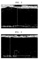
- FIGS. 2 and 3 show filed emission scanning electron microscope (FE-SEM) images of cross-sections of an alloy ribbon prepared by melt-spinning according to Example 1 and Comparative Example 1.
- the alloy ribbon prepared in Example 1 had a uniform dispersion of particle size distribution of silicon nanoparticles, in which silicon nanoparticles were precipitated in about 91 % of a distribution area thereof.
- the alloy ribbon prepared in Comparative Example 1 had a wide dispersion of particle size distribution of silicon nanoparticles, in which silicon nanoparticles were precipitated in about 69% of a distribution area.
- TEM images thereof were analyzed. An image of the distributed silicon nanoparticles was obtained by using the TEM, and a dispersion according to the size of the silicon nanoparticles was obtained by using an image analyzer. TEM images of Example 1 and Comparative Example 1 are shown in FIGS. 4 and 5 .
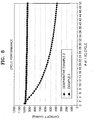
- FIGS. 4 and 5 Dark portions of the TEM images of FIGS. 4 and 5 indicate silicon nanoparticles, and particle size distributions of the silicon nanoparticles obtained by using an image analyzer is shown in FIG. 6 .
- the range of D10 to D90 of silicon nanoparticles prepared in Comparative Example 1 shows a wide dispersion in the range of about 5 to about 300 nm
- the range of D10 to D90 of silicon nanoparticles prepared in Example 1 shows a narrow dispersion in the range of about 10 to about 90 nm.
- the negative active material prepared in Example 1 has better size dispersion characteristics of silicon nanoparticles than those prepared in Comparative Example 1.
- a negative active material slurry was prepared by mixing the negative active material prepared in Example 1, LSR7 (including 23 wt% of PAl and 97 wt% of N-methyl-2-pyrollidone, Hitachi Chemical) as a binder, ketjen black as a conductive agent at a weight ratio of 84:4:8 and adding N-methylpyrollidone to the mixture to adjust viscosity until a solid content thereof reached 60 wt%.
- the prepared slurry was coated on a copper foil current collector having a thickness of 10 ⁇ m to manufacture a negative electrode plate. The completely coated electrode plate was dried at the temperature of 110°C for 15 minutes, followed by pressing, thereby completing the manufacture of a negative electrode having a density of 1.5 g/cc.
- the dried negative electrode plate was heat-treated in a vacuum at 350°C for 1 hour, and the electrode plate was cut to a size of 16 mm to prepare a negative electrode to be applied to a coin cell.
- An Li metal as a reference electrode and a polyethylene separator having a thickness of 20 ⁇ m (product name: STAR20, Asahi) were used, and an electrolyte was injected thereto, and the resultant structure was pressed to complete the manufacture of a 2016R type coin cell.
- the electrolyte was 1.10 M LiPF 6 dissolved in a mixed solvent of ethylene carbonate (EC), ethylmethyl carbonate (EMC), and diethyl carbonate (DEC) at a volumetric ratio of EC:EMC:DEC of 3:3:4.
- EC ethylene carbonate
- EMC ethylmethyl carbonate
- DEC diethyl carbonate
- a coin cell was manufactured in the same manner as in Example 2, except that the negative active material prepared in Comparative Example 1 was used instead of the negative active material prepared in Example 1.
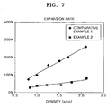
- Example 2 The coin cells prepared in Example 2 and Comparative Example 2 were charged (formation) at a current of 0.1 C, and then the coin cells were disassembled to compare a thickness of a negative electrode plate before and after the charging and a volumetric expansion ratio of the negative electrodes of the coin cells was measured. The results thereof are shown in FIG. 7 and Table 1.
- Density Expansion rate Density Expansion rate 0.80 75% 0.84 30% 1.00 100% 1.00 39% 1.25 156% 1.22 44% 1.50 179% 1.54 43% 1.70 200% 1.78 58% 2.10 260% 2.12 80%
- Capacity retention ratio % Discharge capacity at each cycle / Discharge capacity at 1 st cycle ⁇ 100
- the discharge capacity of the coin cell prepared in Example 2 was higher than the discharge capacity of that of Comparative Example 2 by about 550 mAh/g after charging and discharging were repeated 50 times at a rate of 1.0 C. While the capacity retention rate of the discharge capacity of the coin cell prepared in Comparative Example 2 was 38%, the capacity retention rate of that of Example 2 was highly maintained as 95% after charging and discharging were repeated 50 times. This is because the volumetric expansion was inhibited by controlling the particle size distribution of the silicon nanoparticles. While the CRR of the coin cell prepared in Comparative Example 2 was low due to volumetric expansion of the active material, the discharge capacity of the coin cell prepared in Example 2 was maintained after 50 times of charging and discharging since the volumetric expansion of the active material was inhibited.
Landscapes
- Chemical & Material Sciences (AREA)
- General Chemical & Material Sciences (AREA)
- Chemical Kinetics & Catalysis (AREA)
- Electrochemistry (AREA)
- Engineering & Computer Science (AREA)
- Manufacturing & Machinery (AREA)
- Materials Engineering (AREA)
- Inorganic Chemistry (AREA)
- Composite Materials (AREA)
- General Physics & Mathematics (AREA)
- Condensed Matter Physics & Semiconductors (AREA)
- Physics & Mathematics (AREA)
- Battery Electrode And Active Subsutance (AREA)
Claims (18)
- Matériau actif négatif comprenant un alliage à base de silicium, dans lequel l'alliage à base de silicium comprend: une matrice à base d'alliage de silicium; et des nanoparticules de silicium réparties dans la matrice, dans lequel une distribution des tailles de particule des nanoparticules de silicium satisfait D10 ≥ 10 nm et D90 ≤ 75 nm.
- Matériau actif négatif selon la revendication 1, dans lequel l'alliage à base de silicium comprend du silicium (Si), et au moins un métal sélectionné parmi le groupe constitué de Ca, Sc, Ti, V, Cr, Mn, Fe, Co, Ni, Cu, Zn, Sr, Y, Zr, Nb, Ba, Lu, Hf, Ta, et d'un élément du groupe du lanthane.
- Matériau actif négatif selon la revendication 1 ou 2, dans lequel la teneur du Si contenu dans l'alliage à base de silicium est de 40 at% ou plus.
- Matériau actif négatif selon l'une quelconque des revendications précédentes, dans lequel l'alliage à base de silicium est représenté par Si-M'-M", où M' est Al, Ti, ou Fe, et M" est Ni, Fe, ou Mn.
- Matériau actif négatif selon la revendication 4, dans lequel l'alliage à base de silicium comprend 40 à 80 at% de Si, 10 à 30 at% de M', et 10 à 30 at% de M", de préférence, l'alliage à base de silicium comprend 60 à 80 at% de Si, 10 à 20 at% de M', et 10 à 20 at% de M".
- Matériau actif négatif selon la revendication 4 ou 5, dans lequel la matrice à base d'alliage de silicium comprend 40 à 60 at% de Si, 20 à 30 at% de M', et 20 à 30 at% de M".
- Matériau actif négatif selon l'une quelconque des revendications précédentes, dans lequel le silicium constituant l'alliage à base de silicium comprend du silicium inactif et du silicium actif, où le silicium inactif forme la matrice à base d'alliage de silicium et le silicium actif est précipité dans la matrice sous la forme de nanoparticules.
- Matériau actif négatif selon l'une quelconque des revendications précédentes, dans lequel plus de 60 % de la taille des particules se situent dans la plage de 28 à 65 nm.
- Matériau actif négatif selon l'une quelconque des revendications précédentes, dans lequel dans la distribution des tailles de particule des nanoparticules de silicium, D50 se situe dans la plage de 35 à 50 nm.
- Matériau actif négatif selon l'une quelconque des revendications précédentes, dans lequel dans la distribution des tailles de particule des nanoparticules de silicium, D90/D10 se situe dans la plage de 8,5 à 10, et D50/D10 se situe dans la plage de 5,5 à 7,2.
- Batterie au lithium comprenant: une électrode négative incluant le matériau actif négatif selon l'une quelconque des revendications précédentes; une électrode positive disposée à l'opposé de l'électrode négative; et un électrolyte disposé entre l'électrode négative et l'électrode positive.
- Procédé de fabrication d'un matériau actif négatif, comprenant:la préparation d'un alliage maître;le refroidissement et la solidification rapidement des masses fondues d'alliage maître pour obtenir un alliage rapidement solidifié comprenant une matrice à base d'alliage de silicium ayant des nanoparticules de silicium réparties dans la matrice, où une distribution des tailles de particule des nanoparticules de silicium satisfait D10 ≥ 10 nm et D90 ≤ 75 nm; etla pulvérisation de l'alliage rapidement solidifié.
- Procédé selon la revendication 12, dans lequel le procédé de refroidissement et de solidification rapide est exécuté en utilisant le filage à l'état fondu.
- Procédé selon la revendication 13, dans lequel l'alliage maître est ajouté à une conduite de moulage par injection d'un dispositif de filage à l'état fondu et fondu par chauffage par induction à haute fréquence dans une atmosphère inerte à une température située dans la plage de 850 à 1 600°C.
- Procédé selon la revendication 14, dans lequel une pression du gaz inerte se situe dans la plage de 10 à 200 Torr (1,33 à 26,669 kPa).
- Procédé selon l'une quelconque des revendications 12 à 15, dans lequel le refroidissement et la solidification des masses fondues de l'alliage maître sont atteints par moulage par injection des masses fondues à une roue tournant à une vitesse située dans la plage de 500 à 5 000 tr/min pour induire la précipitation des nanoparticules de silicium.
- Procédé selon l'une quelconque des revendications 12 à 16, dans lequel les masses fondues sont moulées par injection en une forme de ruban, où l'épaisseur de la forme de ruban est de 5 à 20 µm, de préférence dans la plage de 7 à 16 µm.
- Procédé selon l'une quelconque des revendications 12 à 17, dans lequel la vitesse de refroidissement est contrôlée pour être supérieure à 1 000°C/s, de préférence dans la plage de 1 000 à 2 000°C/s.
Applications Claiming Priority (2)
| Application Number | Priority Date | Filing Date | Title |
|---|---|---|---|
| US201261621380P | 2012-04-06 | 2012-04-06 | |
| US13/742,281 US9123955B2 (en) | 2012-04-06 | 2013-01-15 | Negative active material, lithium battery including the material, and method for manufacturing the material |
Publications (2)
| Publication Number | Publication Date |
|---|---|
| EP2648249A1 EP2648249A1 (fr) | 2013-10-09 |
| EP2648249B1 true EP2648249B1 (fr) | 2016-03-23 |
Family
ID=48139705
Family Applications (1)
| Application Number | Title | Priority Date | Filing Date |
|---|---|---|---|
| EP13162609.5A Active EP2648249B1 (fr) | 2012-04-06 | 2013-04-05 | Matériau actif négatif, batterie au lithium comprenant ce matériau et procédé de fabrication du matériau |
Country Status (3)
| Country | Link |
|---|---|
| US (1) | US9123955B2 (fr) |
| EP (1) | EP2648249B1 (fr) |
| KR (1) | KR101749506B1 (fr) |
Cited By (1)
| Publication number | Priority date | Publication date | Assignee | Title |
|---|---|---|---|---|
| EP3089243A4 (fr) * | 2013-12-24 | 2017-07-05 | Iljin Electronic Co., Ltd. | Matériau actif négatif pour batterie rechargeable au lithium |
Families Citing this family (42)
| Publication number | Priority date | Publication date | Assignee | Title |
|---|---|---|---|---|
| CN102575028B (zh) * | 2009-10-09 | 2015-06-17 | 宇部兴产株式会社 | 着色聚酰亚胺成型体及其制造方法 |
| GB2492167C (en) | 2011-06-24 | 2018-12-05 | Nexeon Ltd | Structured particles |
| JP2015510666A (ja) | 2012-01-30 | 2015-04-09 | ネクソン リミテッドNexeon Limited | Si/C電気活性材料組成物 |
| US9461309B2 (en) | 2012-08-21 | 2016-10-04 | Kratos LLC | Group IVA functionalized particles and methods of use thereof |
| EP2888778A1 (fr) | 2012-08-21 | 2015-07-01 | Kratos LLC | Particules fonctionnalisées du groupe iva et leurs procédés d'utilisation |
| KR101496309B1 (ko) * | 2013-08-09 | 2015-02-26 | 오씨아이 주식회사 | 음극활물질용 실리콘 슬러리 및 탄소-실리콘 복합체 |
| KR101728753B1 (ko) * | 2013-08-22 | 2017-04-20 | 삼성에스디아이 주식회사 | 음극 활물질, 이를 채용한 음극과 리튬 전지, 및 상기 음극 활물질의 제조방법 |
| KR101749187B1 (ko) * | 2013-11-19 | 2017-06-20 | 삼성에스디아이 주식회사 | 음극 활물질, 이를 채용한 음극과 리튬 전지 및 상기 음극 활물질의 제조방법 |
| KR101785268B1 (ko) | 2013-12-10 | 2017-10-16 | 삼성에스디아이 주식회사 | 음극 활물질, 이를 포함하는 리튬 전지 및 상기 음극 활물질의 제조방법 |
| KR102152883B1 (ko) * | 2014-01-27 | 2020-09-07 | 삼성에스디아이 주식회사 | 음극 활물질, 이를 채용한 음극과 리튬 전지, 및 상기 음극 활물질의 제조방법 |
| KR101567203B1 (ko) | 2014-04-09 | 2015-11-09 | (주)오렌지파워 | 이차 전지용 음극 활물질 및 이의 방법 |
| KR101604352B1 (ko) | 2014-04-22 | 2016-03-18 | (주)오렌지파워 | 음극 활물질 및 이를 포함하는 리튬 이차 전지 |
| EP2966710A1 (fr) * | 2014-07-08 | 2016-01-13 | Umicore SA | Pluralité de domaines de silicium et son utilisation, particule composite faite de celui-ci et électrode pour batterie |
| EP2966037A1 (fr) * | 2014-07-08 | 2016-01-13 | Umicore SA | Particule composite comprenant une matrice à base de carbone et dans laquelle sont incorporées des particules de silicium, poudre constituée de telles particules composites, utilisation de ces particules composites et électrode pour batterie |
| CN106663834A (zh) * | 2014-07-22 | 2017-05-10 | 瑞克锐斯株式会社 | 硅二次电池单元及利用此的电力机动车用电池模块 |
| KR101550781B1 (ko) | 2014-07-23 | 2015-09-08 | (주)오렌지파워 | 2 차 전지용 실리콘계 활물질 입자의 제조 방법 |
| KR102234287B1 (ko) * | 2014-08-08 | 2021-03-31 | 삼성에스디아이 주식회사 | 음극 활물질, 이를 채용한 음극과 리튬 전지, 및 상기 음극 활물질의 제조방법 |
| GB2533161C (en) | 2014-12-12 | 2019-07-24 | Nexeon Ltd | Electrodes for metal-ion batteries |
| FR3048821B1 (fr) | 2016-03-08 | 2021-12-17 | Commissariat Energie Atomique | Encre comprenant un melange d'acides polyacryliques pour la realisation d'une electrode de batterie lithium-ion, et electrode obtenue avec une telle encre |
| BR112019000112A2 (pt) | 2016-07-05 | 2019-04-09 | Kratos LLC | partículas do grupo iva micrônicas e sub-micrônicas pré-litiadas passivadas e métodos de preparação das mesmas |
| EP3496200A4 (fr) * | 2016-08-05 | 2020-04-22 | Envision AESC Energy Devices Ltd. | Batterie et module de batterie |
| KR101918815B1 (ko) | 2016-08-23 | 2018-11-15 | 넥시온 엘티디. | 이차 전지용 음극 활물질 및 이의 제조 방법 |
| KR101773719B1 (ko) | 2016-08-23 | 2017-09-01 | (주)오렌지파워 | 2 차 전지용 실리콘계 활물질 입자 및 이의 제조 방법 |
| WO2018183909A1 (fr) | 2017-03-31 | 2018-10-04 | Kratos LLC | Matériau d'électrode négative préchargé pour batterie secondaire |
| CN107093738B (zh) * | 2017-04-24 | 2019-12-24 | 广东烛光新能源科技有限公司 | 一种纳米硅基材料的制备方法 |
| WO2018225971A1 (fr) * | 2017-06-07 | 2018-12-13 | 한국생산기술연구원 | Matériau actif d'anode destiné à une batterie secondaire au lithium, anode destinée à une batterie secondaire au lithium, et batterie secondaire au lithium comprenant une telle anode |
| KR102293887B1 (ko) * | 2017-07-25 | 2021-08-25 | 주식회사 엘지에너지솔루션 | 불산을 저감하는 물질을 포함하는 전지 분리막 |
| JP7140125B2 (ja) * | 2017-08-24 | 2022-09-21 | 日本電気株式会社 | リチウムイオン二次電池用負極およびこれを含むリチウムイオン二次電池 |
| US12567582B2 (en) | 2018-02-07 | 2026-03-03 | Umicore | Silicon-based powder, electrode and battery comprising such a powder |
| CN108746628B (zh) * | 2018-06-05 | 2019-12-17 | 中北大学 | 一种注射成型制备石墨烯增强镁基复合材料的方法 |
| KR102321503B1 (ko) * | 2018-06-12 | 2021-11-02 | 주식회사 엘지에너지솔루션 | 리튬 이차전지용 음극활물질 및 이를 포함하는 리튬 이차전지 |
| CN109509862A (zh) * | 2018-11-09 | 2019-03-22 | 浙江工业职业技术学院 | 一种陶瓷涂覆隔离膜及其制备方法 |
| CN110085851B (zh) * | 2019-05-20 | 2021-10-26 | 拓米(成都)应用技术研究院有限公司 | 一种锂电池含硅锡合金负极材料及其制备方法 |
| KR102773404B1 (ko) * | 2019-09-16 | 2025-02-25 | 에스케이온 주식회사 | 리튬 이차 전지 및 리튬 이차 전지용 음극의 제조 방법 |
| WO2022205154A1 (fr) * | 2021-03-31 | 2022-10-06 | 宁德新能源科技有限公司 | Matériau actif d'électrode négative, appareil électrochimique et appareil électronique |
| KR102376462B1 (ko) * | 2021-10-19 | 2022-03-22 | (주)창성 | 리튬 이차전지용 음극활물질, 이를 포함하는 리튬 이차전지 및 그 제조방법 |
| CN114447313B (zh) * | 2022-01-28 | 2024-01-16 | 江苏集芯半导体硅材料研究院有限公司 | 硅基负极材料的制备方法及生产装置 |
| CN114672713B (zh) * | 2022-04-21 | 2022-09-16 | 胜华新能源科技(东营)有限公司 | 含锂金属硅的制备方法、含锂金属硅、含锂SiO及其应用 |
| EP4290619A4 (fr) * | 2022-04-21 | 2024-10-02 | Shinghwa Amperex Technology (Dongying) Co., Ltd. | Procédé de préparation d'un métal au silicium contenant du lithium, métal au silicium contenant du lithium, sio contenant du lithium et son utilisation |
| JP2025525963A (ja) * | 2023-04-20 | 2025-08-07 | エルジー エナジー ソリューション リミテッド | 負極活物質、負極活物質の製造方法、負極組成物、これを含むリチウム二次電池用負極、および負極を含むリチウム二次電池 |
| CN117954592A (zh) * | 2023-12-26 | 2024-04-30 | 博赛利斯(南京)有限公司 | 一种负极活性材料及其制备方法和应用 |
| KR102920169B1 (ko) * | 2025-01-13 | 2026-01-30 | 일진전기 주식회사 | 실리콘 합금 기반의 음극활물질, 음극, 및 이를 포함하는 리튬 이차전지 |
Family Cites Families (10)
| Publication number | Priority date | Publication date | Assignee | Title |
|---|---|---|---|---|
| US7736806B2 (en) | 2002-03-20 | 2010-06-15 | Panasonic Corporation | Cathode material and non-aqueous electrolyte secondary battery using it |
| JP3769277B2 (ja) | 2003-04-17 | 2006-04-19 | 株式会社東芝 | 非水電解質二次電池 |
| JP3841779B2 (ja) | 2003-08-22 | 2006-11-01 | 三星エスディアイ株式会社 | リチウム二次電池用負極活物質及びその製造方法並びにリチウム二次電池 |
| US7955735B2 (en) | 2004-11-15 | 2011-06-07 | Panasonic Corporation | Non-aqueous electrolyte secondary battery |
| JP5030414B2 (ja) | 2004-11-15 | 2012-09-19 | パナソニック株式会社 | 非水電解質二次電池 |
| JP5072323B2 (ja) | 2005-11-17 | 2012-11-14 | パナソニック株式会社 | 非水電解質二次電池、および非水電解質二次電池用負極材料の製造方法 |
| US7662514B2 (en) | 2005-11-17 | 2010-02-16 | Panasonic Corporation | Non-aqueous electrolyte secondary battery and method for producing negative electrode material for non-aqueous electrolyte secondary battery |
| JP5361233B2 (ja) | 2008-03-31 | 2013-12-04 | 三洋電機株式会社 | リチウム二次電池及びその製造方法 |
| KR101352672B1 (ko) | 2008-12-30 | 2014-01-16 | 주식회사 엘지화학 | 이차전지용 음극 활물질 |
| JP5520538B2 (ja) | 2009-08-03 | 2014-06-11 | 古河電気工業株式会社 | ナノサイズ粒子を含むリチウムイオン二次電池用負極材料、リチウムイオン二次電池用負極、リチウムイオン二次電池 |
-
2013
- 2013-01-15 US US13/742,281 patent/US9123955B2/en active Active
- 2013-04-05 KR KR1020130037681A patent/KR101749506B1/ko active Active
- 2013-04-05 EP EP13162609.5A patent/EP2648249B1/fr active Active
Cited By (1)
| Publication number | Priority date | Publication date | Assignee | Title |
|---|---|---|---|---|
| EP3089243A4 (fr) * | 2013-12-24 | 2017-07-05 | Iljin Electronic Co., Ltd. | Matériau actif négatif pour batterie rechargeable au lithium |
Also Published As
| Publication number | Publication date |
|---|---|
| KR101749506B1 (ko) | 2017-06-21 |
| KR20130114007A (ko) | 2013-10-16 |
| US9123955B2 (en) | 2015-09-01 |
| EP2648249A1 (fr) | 2013-10-09 |
| US20130266865A1 (en) | 2013-10-10 |
Similar Documents
| Publication | Publication Date | Title |
|---|---|---|
| EP2648249B1 (fr) | Matériau actif négatif, batterie au lithium comprenant ce matériau et procédé de fabrication du matériau | |
| CN110870115B (zh) | 负极活性材料、包含其的负极和锂二次电池 | |
| EP2162936B1 (fr) | Matériau anodique d'une excellente conductivité et son emploi dans une batterie auxiliaire grande puissance | |
| EP3038193B1 (fr) | Matériau actif négatif et batterie de lithium rechargeable l'incluant | |
| KR102119156B1 (ko) | 양극 활물질, 이를 채용한 리튬전지 및 상기 양극 활물질의 제조방법 | |
| US9406933B2 (en) | Negative active material, negative electrode and lithium battery including negative active material, and method of manufacturing negative active material | |
| US10177374B2 (en) | Silicon-containing negative active material, method of preparing the same, negative electrode including the same, and lithium secondary battery including negative electrode | |
| EP2916375B1 (fr) | Matériau actif négatif, électrode positive et batterie au lithium comprenant le matériau actif négatif et procédé de fabrication du matériau actif négatif | |
| US9356287B2 (en) | Negative active material, negative electrode and lithium battery including the negative active material, and method of preparing the negative active material | |
| EP4109593A1 (fr) | Anode et batterie secondaire la comprenant | |
| CN106953090B (zh) | 负极活性物质及包括所述物质的负极和锂电池 | |
| US20240351886A1 (en) | Negative electrode active material, manufacturing method of negative electrode active material, negative electrode composition, negative electrode for lithium secondary battery including same, and lithium secondary battery including negative electrode | |
| EP4362133A1 (fr) | Matériau actif d'électrode négative, son procédé de préparation et batterie secondaire au lithium comprenant celui-ci | |
| EP4557396A1 (fr) | Matériau actif d'anode, procédé de préparation de matériau actif d'anode, composition d'anode, anode de batterie secondaire au lithium le comprenant, et batterie secondaire au lithium comprenant une anode | |
| KR20260063797A (ko) | 리튬 이차 전지용 음극 활물질, 이의 제조방법 및 이를 포함하는 리튬 이차 전지 | |
| EP4712157A1 (fr) | Anode et son procédé de fabrication | |
| EP4723212A1 (fr) | Matériau actif de cathode pour batterie secondaire au lithium, son procédé de fabrication et batterie secondaire au lithium le comprenant | |
| KR20260063796A (ko) | 리튬 이차 전지용 음극 활물질, 이의 제조방법 및 이를 포함하는 리튬 이차 전지 | |
| JP2025154092A (ja) | リチウムイオン二次電池用負極材及びリチウムイオン二次電池 | |
| CN121311971A (zh) | 负极活性材料、负极活性材料的制造方法、负极组合物、包含其的锂二次电池用负极和包含负极的锂二次电池 |
Legal Events
| Date | Code | Title | Description |
|---|---|---|---|
| PUAI | Public reference made under article 153(3) epc to a published international application that has entered the european phase |
Free format text: ORIGINAL CODE: 0009012 |
|
| AK | Designated contracting states |
Kind code of ref document: A1 Designated state(s): AL AT BE BG CH CY CZ DE DK EE ES FI FR GB GR HR HU IE IS IT LI LT LU LV MC MK MT NL NO PL PT RO RS SE SI SK SM TR |
|
| AX | Request for extension of the european patent |
Extension state: BA ME |
|
| RIN1 | Information on inventor provided before grant (corrected) |
Inventor name: LEE, CHUN-GYOO Inventor name: MOON, SUNG-HWAN Inventor name: JEONG, CHANG-UI Inventor name: KIM, JAE-HYUK Inventor name: CHOI, JONG-SEO Inventor name: SUH, SOON-SUNG Inventor name: MATULEVICH, YURY Inventor name: KWON, SEUNG-UK Inventor name: PARK, YO-HAN |
|
| 17P | Request for examination filed |
Effective date: 20140403 |
|
| RBV | Designated contracting states (corrected) |
Designated state(s): AL AT BE BG CH CY CZ DE DK EE ES FI FR GB GR HR HU IE IS IT LI LT LU LV MC MK MT NL NO PL PT RO RS SE SI SK SM TR |
|
| GRAP | Despatch of communication of intention to grant a patent |
Free format text: ORIGINAL CODE: EPIDOSNIGR1 |
|
| RIC1 | Information provided on ipc code assigned before grant |
Ipc: H01M 4/38 20060101AFI20141124BHEP Ipc: H01M 4/62 20060101ALI20141124BHEP |
|
| INTG | Intention to grant announced |
Effective date: 20141211 |
|
| RIN1 | Information on inventor provided before grant (corrected) |
Inventor name: MATULEVICH, YURY Inventor name: LEE, CHUN-GYOO Inventor name: CHOI, JONG-SEO Inventor name: JEONG, CHANG-UI Inventor name: SUH, SOON-SUNG Inventor name: PARK, YO-HAN Inventor name: KIM, JAE-HYUK Inventor name: MOON, SUNG-HWAN Inventor name: KWON, SEUNG-UK |
|
| GRAP | Despatch of communication of intention to grant a patent |
Free format text: ORIGINAL CODE: EPIDOSNIGR1 |
|
| INTG | Intention to grant announced |
Effective date: 20150918 |
|
| GRAS | Grant fee paid |
Free format text: ORIGINAL CODE: EPIDOSNIGR3 |
|
| GRAA | (expected) grant |
Free format text: ORIGINAL CODE: 0009210 |
|
| AK | Designated contracting states |
Kind code of ref document: B1 Designated state(s): AL AT BE BG CH CY CZ DE DK EE ES FI FR GB GR HR HU IE IS IT LI LT LU LV MC MK MT NL NO PL PT RO RS SE SI SK SM TR |
|
| REG | Reference to a national code |
Ref country code: GB Ref legal event code: FG4D |
|
| REG | Reference to a national code |
Ref country code: CH Ref legal event code: EP |
|
| REG | Reference to a national code |
Ref country code: AT Ref legal event code: REF Ref document number: 783936 Country of ref document: AT Kind code of ref document: T Effective date: 20160415 |
|
| REG | Reference to a national code |
Ref country code: IE Ref legal event code: FG4D |
|
| REG | Reference to a national code |
Ref country code: DE Ref legal event code: R096 Ref document number: 602013005624 Country of ref document: DE |
|
| REG | Reference to a national code |
Ref country code: FR Ref legal event code: PLFP Year of fee payment: 4 |
|
| REG | Reference to a national code |
Ref country code: LT Ref legal event code: MG4D |
|
| REG | Reference to a national code |
Ref country code: NL Ref legal event code: MP Effective date: 20160323 |
|
| PG25 | Lapsed in a contracting state [announced via postgrant information from national office to epo] |
Ref country code: FI Free format text: LAPSE BECAUSE OF FAILURE TO SUBMIT A TRANSLATION OF THE DESCRIPTION OR TO PAY THE FEE WITHIN THE PRESCRIBED TIME-LIMIT Effective date: 20160323 Ref country code: HR Free format text: LAPSE BECAUSE OF FAILURE TO SUBMIT A TRANSLATION OF THE DESCRIPTION OR TO PAY THE FEE WITHIN THE PRESCRIBED TIME-LIMIT Effective date: 20160323 Ref country code: NO Free format text: LAPSE BECAUSE OF FAILURE TO SUBMIT A TRANSLATION OF THE DESCRIPTION OR TO PAY THE FEE WITHIN THE PRESCRIBED TIME-LIMIT Effective date: 20160623 Ref country code: GR Free format text: LAPSE BECAUSE OF FAILURE TO SUBMIT A TRANSLATION OF THE DESCRIPTION OR TO PAY THE FEE WITHIN THE PRESCRIBED TIME-LIMIT Effective date: 20160624 |
|
| REG | Reference to a national code |
Ref country code: AT Ref legal event code: MK05 Ref document number: 783936 Country of ref document: AT Kind code of ref document: T Effective date: 20160323 |
|
| PG25 | Lapsed in a contracting state [announced via postgrant information from national office to epo] |
Ref country code: NL Free format text: LAPSE BECAUSE OF FAILURE TO SUBMIT A TRANSLATION OF THE DESCRIPTION OR TO PAY THE FEE WITHIN THE PRESCRIBED TIME-LIMIT Effective date: 20160323 Ref country code: RS Free format text: LAPSE BECAUSE OF FAILURE TO SUBMIT A TRANSLATION OF THE DESCRIPTION OR TO PAY THE FEE WITHIN THE PRESCRIBED TIME-LIMIT Effective date: 20160323 Ref country code: SE Free format text: LAPSE BECAUSE OF FAILURE TO SUBMIT A TRANSLATION OF THE DESCRIPTION OR TO PAY THE FEE WITHIN THE PRESCRIBED TIME-LIMIT Effective date: 20160323 Ref country code: LV Free format text: LAPSE BECAUSE OF FAILURE TO SUBMIT A TRANSLATION OF THE DESCRIPTION OR TO PAY THE FEE WITHIN THE PRESCRIBED TIME-LIMIT Effective date: 20160323 Ref country code: LT Free format text: LAPSE BECAUSE OF FAILURE TO SUBMIT A TRANSLATION OF THE DESCRIPTION OR TO PAY THE FEE WITHIN THE PRESCRIBED TIME-LIMIT Effective date: 20160323 Ref country code: BE Free format text: LAPSE BECAUSE OF NON-PAYMENT OF DUE FEES Effective date: 20160430 |
|
| PG25 | Lapsed in a contracting state [announced via postgrant information from national office to epo] |
Ref country code: EE Free format text: LAPSE BECAUSE OF FAILURE TO SUBMIT A TRANSLATION OF THE DESCRIPTION OR TO PAY THE FEE WITHIN THE PRESCRIBED TIME-LIMIT Effective date: 20160323 Ref country code: PL Free format text: LAPSE BECAUSE OF FAILURE TO SUBMIT A TRANSLATION OF THE DESCRIPTION OR TO PAY THE FEE WITHIN THE PRESCRIBED TIME-LIMIT Effective date: 20160323 Ref country code: IS Free format text: LAPSE BECAUSE OF FAILURE TO SUBMIT A TRANSLATION OF THE DESCRIPTION OR TO PAY THE FEE WITHIN THE PRESCRIBED TIME-LIMIT Effective date: 20160723 |
|
| PG25 | Lapsed in a contracting state [announced via postgrant information from national office to epo] |
Ref country code: RO Free format text: LAPSE BECAUSE OF FAILURE TO SUBMIT A TRANSLATION OF THE DESCRIPTION OR TO PAY THE FEE WITHIN THE PRESCRIBED TIME-LIMIT Effective date: 20160323 Ref country code: PT Free format text: LAPSE BECAUSE OF FAILURE TO SUBMIT A TRANSLATION OF THE DESCRIPTION OR TO PAY THE FEE WITHIN THE PRESCRIBED TIME-LIMIT Effective date: 20160725 Ref country code: CZ Free format text: LAPSE BECAUSE OF FAILURE TO SUBMIT A TRANSLATION OF THE DESCRIPTION OR TO PAY THE FEE WITHIN THE PRESCRIBED TIME-LIMIT Effective date: 20160323 Ref country code: ES Free format text: LAPSE BECAUSE OF FAILURE TO SUBMIT A TRANSLATION OF THE DESCRIPTION OR TO PAY THE FEE WITHIN THE PRESCRIBED TIME-LIMIT Effective date: 20160323 Ref country code: SK Free format text: LAPSE BECAUSE OF FAILURE TO SUBMIT A TRANSLATION OF THE DESCRIPTION OR TO PAY THE FEE WITHIN THE PRESCRIBED TIME-LIMIT Effective date: 20160323 Ref country code: AT Free format text: LAPSE BECAUSE OF FAILURE TO SUBMIT A TRANSLATION OF THE DESCRIPTION OR TO PAY THE FEE WITHIN THE PRESCRIBED TIME-LIMIT Effective date: 20160323 Ref country code: SM Free format text: LAPSE BECAUSE OF FAILURE TO SUBMIT A TRANSLATION OF THE DESCRIPTION OR TO PAY THE FEE WITHIN THE PRESCRIBED TIME-LIMIT Effective date: 20160323 |
|
| REG | Reference to a national code |
Ref country code: CH Ref legal event code: PL |
|
| PG25 | Lapsed in a contracting state [announced via postgrant information from national office to epo] |
Ref country code: BE Free format text: LAPSE BECAUSE OF FAILURE TO SUBMIT A TRANSLATION OF THE DESCRIPTION OR TO PAY THE FEE WITHIN THE PRESCRIBED TIME-LIMIT Effective date: 20160323 Ref country code: IT Free format text: LAPSE BECAUSE OF FAILURE TO SUBMIT A TRANSLATION OF THE DESCRIPTION OR TO PAY THE FEE WITHIN THE PRESCRIBED TIME-LIMIT Effective date: 20160323 |
|
| REG | Reference to a national code |
Ref country code: DE Ref legal event code: R097 Ref document number: 602013005624 Country of ref document: DE |
|
| REG | Reference to a national code |
Ref country code: IE Ref legal event code: MM4A |
|
| PLBE | No opposition filed within time limit |
Free format text: ORIGINAL CODE: 0009261 |
|
| STAA | Information on the status of an ep patent application or granted ep patent |
Free format text: STATUS: NO OPPOSITION FILED WITHIN TIME LIMIT |
|
| PG25 | Lapsed in a contracting state [announced via postgrant information from national office to epo] |
Ref country code: DK Free format text: LAPSE BECAUSE OF FAILURE TO SUBMIT A TRANSLATION OF THE DESCRIPTION OR TO PAY THE FEE WITHIN THE PRESCRIBED TIME-LIMIT Effective date: 20160323 Ref country code: LI Free format text: LAPSE BECAUSE OF NON-PAYMENT OF DUE FEES Effective date: 20160430 Ref country code: CH Free format text: LAPSE BECAUSE OF NON-PAYMENT OF DUE FEES Effective date: 20160430 |
|
| PG25 | Lapsed in a contracting state [announced via postgrant information from national office to epo] |
Ref country code: BG Free format text: LAPSE BECAUSE OF FAILURE TO SUBMIT A TRANSLATION OF THE DESCRIPTION OR TO PAY THE FEE WITHIN THE PRESCRIBED TIME-LIMIT Effective date: 20160623 |
|
| 26N | No opposition filed |
Effective date: 20170102 |
|
| REG | Reference to a national code |
Ref country code: FR Ref legal event code: PLFP Year of fee payment: 5 |
|
| PG25 | Lapsed in a contracting state [announced via postgrant information from national office to epo] |
Ref country code: IE Free format text: LAPSE BECAUSE OF NON-PAYMENT OF DUE FEES Effective date: 20160405 Ref country code: SI Free format text: LAPSE BECAUSE OF FAILURE TO SUBMIT A TRANSLATION OF THE DESCRIPTION OR TO PAY THE FEE WITHIN THE PRESCRIBED TIME-LIMIT Effective date: 20160323 |
|
| REG | Reference to a national code |
Ref country code: FR Ref legal event code: PLFP Year of fee payment: 6 |
|
| PG25 | Lapsed in a contracting state [announced via postgrant information from national office to epo] |
Ref country code: HU Free format text: LAPSE BECAUSE OF FAILURE TO SUBMIT A TRANSLATION OF THE DESCRIPTION OR TO PAY THE FEE WITHIN THE PRESCRIBED TIME-LIMIT; INVALID AB INITIO Effective date: 20130405 Ref country code: CY Free format text: LAPSE BECAUSE OF FAILURE TO SUBMIT A TRANSLATION OF THE DESCRIPTION OR TO PAY THE FEE WITHIN THE PRESCRIBED TIME-LIMIT Effective date: 20160323 |
|
| PG25 | Lapsed in a contracting state [announced via postgrant information from national office to epo] |
Ref country code: MT Free format text: LAPSE BECAUSE OF NON-PAYMENT OF DUE FEES Effective date: 20160430 Ref country code: LU Free format text: LAPSE BECAUSE OF NON-PAYMENT OF DUE FEES Effective date: 20160405 Ref country code: MK Free format text: LAPSE BECAUSE OF FAILURE TO SUBMIT A TRANSLATION OF THE DESCRIPTION OR TO PAY THE FEE WITHIN THE PRESCRIBED TIME-LIMIT Effective date: 20160323 Ref country code: TR Free format text: LAPSE BECAUSE OF FAILURE TO SUBMIT A TRANSLATION OF THE DESCRIPTION OR TO PAY THE FEE WITHIN THE PRESCRIBED TIME-LIMIT Effective date: 20160323 Ref country code: MC Free format text: LAPSE BECAUSE OF FAILURE TO SUBMIT A TRANSLATION OF THE DESCRIPTION OR TO PAY THE FEE WITHIN THE PRESCRIBED TIME-LIMIT Effective date: 20160323 |
|
| PG25 | Lapsed in a contracting state [announced via postgrant information from national office to epo] |
Ref country code: AL Free format text: LAPSE BECAUSE OF FAILURE TO SUBMIT A TRANSLATION OF THE DESCRIPTION OR TO PAY THE FEE WITHIN THE PRESCRIBED TIME-LIMIT Effective date: 20160323 |
|
| P01 | Opt-out of the competence of the unified patent court (upc) registered |
Effective date: 20230528 |
|
| PGFP | Annual fee paid to national office [announced via postgrant information from national office to epo] |
Ref country code: DE Payment date: 20250408 Year of fee payment: 13 |
|
| PGFP | Annual fee paid to national office [announced via postgrant information from national office to epo] |
Ref country code: GB Payment date: 20250403 Year of fee payment: 13 |
|
| PGFP | Annual fee paid to national office [announced via postgrant information from national office to epo] |
Ref country code: FR Payment date: 20250409 Year of fee payment: 13 |