EP2648420B1 - Summervorrichtung für Fahrzeugalarmsystem - Google Patents
Summervorrichtung für Fahrzeugalarmsystem Download PDFInfo
- Publication number
- EP2648420B1 EP2648420B1 EP12163123.8A EP12163123A EP2648420B1 EP 2648420 B1 EP2648420 B1 EP 2648420B1 EP 12163123 A EP12163123 A EP 12163123A EP 2648420 B1 EP2648420 B1 EP 2648420B1
- Authority
- EP
- European Patent Office
- Prior art keywords
- sound
- vehicle
- transducer element
- transducer
- sounder device
- Prior art date
- Legal status (The legal status is an assumption and is not a legal conclusion. Google has not performed a legal analysis and makes no representation as to the accuracy of the status listed.)
- Active
Links
Images

Classifications
-
- H—ELECTRICITY
- H04—ELECTRIC COMMUNICATION TECHNIQUE
- H04R—LOUDSPEAKERS, MICROPHONES, GRAMOPHONE PICK-UPS OR LIKE ACOUSTIC ELECTROMECHANICAL TRANSDUCERS; ELECTRIC HEARING AIDS; PUBLIC ADDRESS SYSTEMS
- H04R1/00—Details of transducers, loudspeakers or microphones
- H04R1/20—Arrangements for obtaining desired frequency or directional characteristics
- H04R1/22—Arrangements for obtaining desired frequency or directional characteristics for obtaining desired frequency characteristic only
- H04R1/24—Structural combinations of separate transducers or of two parts of the same transducer and responsive respectively to two or more frequency ranges
-
- B—PERFORMING OPERATIONS; TRANSPORTING
- B60—VEHICLES IN GENERAL
- B60R—VEHICLES, VEHICLE FITTINGS, OR VEHICLE PARTS, NOT OTHERWISE PROVIDED FOR
- B60R25/00—Fittings or systems for preventing or indicating unauthorised use or theft of vehicles
- B60R25/10—Fittings or systems for preventing or indicating unauthorised use or theft of vehicles actuating a signalling device
- B60R25/1018—Alarm systems characterised by features related to the general power supply
-
- G—PHYSICS
- G08—SIGNALLING
- G08B—SIGNALLING SYSTEMS, e.g. PERSONAL CALLING SYSTEMS; ORDER TELEGRAPHS; ALARM SYSTEMS
- G08B3/00—Audible signalling systems, e.g. audible personal calling systems
- G08B3/10—Audible signalling systems, e.g. audible personal calling systems using electric transmission; using electromagnetic transmission
-
- B—PERFORMING OPERATIONS; TRANSPORTING
- B60—VEHICLES IN GENERAL
- B60R—VEHICLES, VEHICLE FITTINGS, OR VEHICLE PARTS, NOT OTHERWISE PROVIDED FOR
- B60R25/00—Fittings or systems for preventing or indicating unauthorised use or theft of vehicles
- B60R25/10—Fittings or systems for preventing or indicating unauthorised use or theft of vehicles actuating a signalling device
- B60R2025/1013—Alarm systems characterised by the type of warning signal, e.g. visual, audible
-
- H—ELECTRICITY
- H04—ELECTRIC COMMUNICATION TECHNIQUE
- H04R—LOUDSPEAKERS, MICROPHONES, GRAMOPHONE PICK-UPS OR LIKE ACOUSTIC ELECTROMECHANICAL TRANSDUCERS; ELECTRIC HEARING AIDS; PUBLIC ADDRESS SYSTEMS
- H04R17/00—Piezoelectric transducers; Electrostrictive transducers
-
- H—ELECTRICITY
- H04—ELECTRIC COMMUNICATION TECHNIQUE
- H04R—LOUDSPEAKERS, MICROPHONES, GRAMOPHONE PICK-UPS OR LIKE ACOUSTIC ELECTROMECHANICAL TRANSDUCERS; ELECTRIC HEARING AIDS; PUBLIC ADDRESS SYSTEMS
- H04R19/00—Electrostatic transducers
- H04R19/02—Loudspeakers
-
- H—ELECTRICITY
- H04—ELECTRIC COMMUNICATION TECHNIQUE
- H04R—LOUDSPEAKERS, MICROPHONES, GRAMOPHONE PICK-UPS OR LIKE ACOUSTIC ELECTROMECHANICAL TRANSDUCERS; ELECTRIC HEARING AIDS; PUBLIC ADDRESS SYSTEMS
- H04R2217/00—Details of magnetostrictive, piezoelectric, or electrostrictive transducers covered by H04R15/00 or H04R17/00 but not provided for in any of their subgroups
-
- H—ELECTRICITY
- H04—ELECTRIC COMMUNICATION TECHNIQUE
- H04R—LOUDSPEAKERS, MICROPHONES, GRAMOPHONE PICK-UPS OR LIKE ACOUSTIC ELECTROMECHANICAL TRANSDUCERS; ELECTRIC HEARING AIDS; PUBLIC ADDRESS SYSTEMS
- H04R2420/00—Details of connection covered by H04R, not provided for in its groups
- H04R2420/01—Input selection or mixing for amplifiers or loudspeakers
-
- H—ELECTRICITY
- H04—ELECTRIC COMMUNICATION TECHNIQUE
- H04R—LOUDSPEAKERS, MICROPHONES, GRAMOPHONE PICK-UPS OR LIKE ACOUSTIC ELECTROMECHANICAL TRANSDUCERS; ELECTRIC HEARING AIDS; PUBLIC ADDRESS SYSTEMS
- H04R2499/00—Aspects covered by H04R or H04S not otherwise provided for in their subgroups
- H04R2499/10—General applications
- H04R2499/13—Acoustic transducers and sound field adaptation in vehicles
-
- H—ELECTRICITY
- H04—ELECTRIC COMMUNICATION TECHNIQUE
- H04R—LOUDSPEAKERS, MICROPHONES, GRAMOPHONE PICK-UPS OR LIKE ACOUSTIC ELECTROMECHANICAL TRANSDUCERS; ELECTRIC HEARING AIDS; PUBLIC ADDRESS SYSTEMS
- H04R3/00—Circuits for transducers
- H04R3/12—Circuits for transducers for distributing signals to two or more loudspeakers
-
- H—ELECTRICITY
- H04—ELECTRIC COMMUNICATION TECHNIQUE
- H04R—LOUDSPEAKERS, MICROPHONES, GRAMOPHONE PICK-UPS OR LIKE ACOUSTIC ELECTROMECHANICAL TRANSDUCERS; ELECTRIC HEARING AIDS; PUBLIC ADDRESS SYSTEMS
- H04R9/00—Transducers of moving-coil, moving-strip, or moving-wire type
- H04R9/06—Loudspeakers
- H04R9/063—Loudspeakers using a plurality of acoustic drivers
Definitions
- the present invention relates to a vehicle alarm system sounder device.
- the present invention further relates to a vehicle alarm system comprising such a sounder device and a vehicle comprising such a vehicle alarm system.
- Vehicle alarm systems may be used to prohibit theft of vehicles and/or theft from vehicles. Such alarm system may be arranged to generate an alarm sound upon an unauthorized entry or attempts of an unauthorized entry of a vehicle, such as a braking of a window of the vehicle or a door-lock picking. In some jurisdictions there are legal requirements of that a sounder device used in vehicle alarm systems only may be used for alarm system purposes. Also, in today's vehicles, there is an increased demand for additional security system generating indicating sounds, such as alarm sounds. These security systems are often vital from a safety perspective. However, an unwanted disadvantage is that such systems often require an increased number of components.
- DE 38 28 634 A1 discloses a vehicle information and alarm system.
- US 2012/057728 A1 and CN 201 898 590 U disclose vehicle sounder devices each comprising two sound generating surfaces.
- US 4 401 848 A discloses a voice overheat warning system for an automotive vehicle.
- An object of the present invention is to provide a vehicle alarm system sounder device which reduces production costs and fulfils legal requirements.
- a vehicle alarm system sounder device comprising a first transducer element and a first sound generating surface, the first transducer element being arranged in connection with the first sound generating surface to thereby generate an alarm sound upon a first signal being sent from a control device.
- the sounder device comprises a second transducer element being arranged in connection with the first sound generating surface, or a second sound generating surface of the sounder device, to thereby generate an indicating sound, being different from the alarm sound, upon a second signal being sent from a control device.
- the sounder device comprises a transducer driver wherein the sounder device comprises a switch having at least a first position and a second position, the first position constituting a position wherein an electrical connection between the transducer driver and the first transducer element is closed, and the second position constituting a position wherein an electrical connection between the transducer driver and the second transducer element is closed, and the control device is a micro-controller arranged to control the switch between the first and the second positions, the transducer driver being adapted to receive the first and second signals being sent from the control device, and adapted to produce a first output signal if the first signal is received, and to produce a second output signal if the second signal is received, wherein the first transducer element is adapted to generate the alarm sound upon being fed with the first output signal, and wherein the second transducer element is adapted to generate the indication sound upon being fed with the second output signal.
- an electrical connection is formed between the transducer driver and the first transducer element.
- the transducer driver may provide the first output signal to the first transducer element, e.g. upon a request from the micro-controller, whereby the first transducer element may generate the alarm sound.
- the micro-controller controls the switch to the second position
- an electrical connection is formed between the transducer driver and the second transducer element.
- the transducer driver may provide the second output signal to the second transducer element, e.g. upon a request from the micro-controller, whereby the second transducer element may generate the indicating sound.
- the vehicle alarm system sounder device is provided with a first transducer element and a second transducer element, wherein the first transducer element is arranged to generate an alarm sound and the second transducer element is arranged to generate an indicating sound, being different from the alarm sound
- the vehicle alarm system sounder device can be used to generate sounds for two different functions, e.g. in two different systems. Since two different functions are achieved by the vehicle alarm system sounder device, production costs are reduced in comparison with the use of two sounder devices and said legal requirements are fulfilled since the sounder device is used for alarm system purposes.
- the first transducer element is arranged in connection with the first sound generating surface
- the second transducer element is arranged in connection with a second sound generating surface of the sounder device.
- the vehicle alarm system sounder device may comprise two sound generating surfaces.
- dimensions of the first sound producing surface differ from dimensions of the second sound generating surface.
- the first and the second sound generating surfaces may be comprised in a shared housing.
- the first transducer element and the second transducer element are arranged in connection with the first sound generating surface.
- the vehicle alarm system sounder device may comprise one sound generating surface, wherein the first and second transducer element are in connection with the one sound generating surface.
- the first transducer element may drive the sound generating surface such that the sound generating surface generates a sound with certain sound characteristics, i.e. a certain frequency and/or sound pressure level
- the second transducer element may drive the sound generating surface such that the sound generating surface generates a sound with a different sound characteristics than the first transducer element.
- the second transducer element may differ from the first transducer element with respect to type of transducer element and/or dimensions of transducer element to thereby produce two sounds with different sound characteristics using only one sound generating surface.
- a sound generating surface may e.g. comprise a membrane and/or a speaker cone.
- the sound generating surface may be made by a plastic material, a paper material, a metallic material, and/or a fabric material.
- the indicating sound may differ from the alarm sound with respect to the sound characteristics such as frequency, alternation of the frequency, and/or sound pressure level. Thereby, the indicating sound may be easy to distinguish from the alarm sound.
- the sounder device is a battery backed up sounder device.
- the sounder device may comprise one or more batteries arranged to supply electric current to the first and/or the second transducer element. Accordingly, in case a burglar is trying to turn off an alarm system by disconnecting a main battery from the sounder device, the sounder device may generate an alarm sound even if the main battery is disconnected from the sounder device.
- the sounder device may be arranged to generate an alarm sound upon a disconnection of the main battery.
- the first transducer element is a piezo element.
- the second transducer element is a piezo element.
- one of the first or the second transducer element may be a piezo element, or both the first and the second transducer elements may be piezo elements. Since piezo elements are small in size in comparison with other types of transducer elements, the sounder device may be produced with small dimensions. Also, piezo elements are less sensitive to environmental disturbances such as moist, temperature variations, and shocks than other types of transducer elements. Therefore, a more robust sounder device may be provided. Furthermore, piezo elements are less expensive than other types of transducer elements. Accordingly, the sounder device may be produced at low cost.
- the vehicle alarm system sounder device may comprise a first piezo element and a second piezo element wherein the first piezo element is arranged in connection with the first sound generating surface to thereby generate an alarm sound upon a first signal being sent from a control device, and the second piezo element is arranged in connection with the first sound generating surface, or a second sound generating surface of the sounder device, to thereby generate an indicating sound, being different from the alarm sound, upon a second signal being sent from a control device.
- the first and/or the second transducer element may comprise an electro-dynamic element, an electro-static element, and/or a magneto-static element.
- the control device may comprise a micro controller, a switch, a relay, a control device comprised in an alarm system, and/or a control device comprised in a security system.
- a first control device comprised in an alarm system
- a second control device comprised in a security system
- one control device is arranged to provide the first and the second signals.
- the one control device may be in communication with an alarm system and a security system.
- the indicating sound constitutes an indicating sound indicating that a driver is leaving, or is about to leave, a vehicle hosting the sounder device, with a propulsion unit being active.
- the vehicle alarm system sounder device may be comprised in a security system being adapted to alert a driver of a vehicle that the driver is leaving, or is about to leave, a vehicle hosting the sounder, with a propulsion unit being active.
- a sounder device is provided fulfilling the upcoming legal proposals at a low cost.
- the indicating sound constitutes an indicating sound indicating that a driver is leaving or is about to leave, a vehicle hosting the sounder device, with a key in a key switch being arranged to activate a propulsion unit.
- key switch may be a mechanical ignition switch, or an electric ignition switch, e.g. an ignition switch being adapted to sense a magnetic field and/or an ignition switch being adapted to sense a presence and/or identification of a key.
- the indicating sound may be generated in case a driver is leaving or is about to leave, a vehicle hosting the sounder, with a key in a key switch being positioned in a propulsion activation position or in an propulsion deactivation position or in any position in between.
- the sounder device is hosted in a vehicle at least partially being propelled by an electric motor, the indicating sound constituting an indicating sound indicating a presence of the vehicle.
- a vehicle at least partially being propelled by an electric motor, may be a hybrid vehicle or an electric vehicle.
- Such vehicles may be more silent than a vehicle being propelled by a combustion engine. Therefore, a sound being generated may facilitate detection of the vehicle.
- the sounder device is hosted in a vehicle at least partially being propelled by an electric motor, and such vehicles may be more silent than a vehicle being propelled by a combustion engine, an indicating sound indicating that a driver is leaving or is about to leave, a vehicle hosting the sounder, with a propulsion unit being active, may alert the driver that the propulsion unit is active.
- Fig. 1 illustrates a vehicle alarm system sounder device 3, comprising a first transducer element 1 and a first sound generating surface 11.
- the first transducer element 1 is arranged in connection with the first sound generating surface 11 to thereby generate an alarm sound 10 upon a first signal being sent from a control device 5.
- the sounder device 3 comprises a second transducer element 2 being arranged in connection with a second sound generating surface 12 of the sounder device 3, to thereby generate an indicating sound 20, being different from the alarm sound 10, upon a second signal being sent from a control device 5.
- the sounder device comprises a transducer driver 16, arranged to drive the first or the second transducer elements 1, 2.
- the sounder device 3 comprises a switch 14 having at least a first position and a second position, the first position constituting a position wherein an electrical connection to the first transducer element 1 is closed, and the second position constituting a position wherein an electrical connection to the second transducer element 2 is closed, and the control device 5 is a micro-controller 5 arranged to control the switch 14 between the first and the second position.
- the micro-controller 5 may be adapted to send a signal to the transducer driver 16 to thereby activate the transducer driver 16.
- the micro-controller 5 may send a first signal to the switch 14 to thereby close an electrical connection between the transducer driver 16 and the first transducer element 1, and a second signal to the transducer driver 16 to thereby activate the transducer driver 16.
- the micro-controller 5 may send a third signal to the switch 14 to thereby close an electrical connection between the transducer driver 16 and the second transducer element 2, and a fourth signal to the transducer driver 16 to thereby activate the transducer driver 16.
- the transducer driver 16 may be adapted to produce a first output signal upon activation by the second signal from the micro-controller 5 and a second output signal upon activation by the fourth signal from the micro-controller 5.
- the first transducer element 1 may be adapted to generate the alarm sound 10 when being fed with the first output signal from the transducer driver 16, and the second transducer element 2 may be adapted to generate the indicating sound 20 when being fed with the second output signal. Thereby, an indication sound 20 being different from the alarm sound 10 may be produced.
- the second transducer element 2 may be of different type and/or of different dimensions than the first transducer element 1.
- the second sound generating surface 12 may be of different type and/or of different dimensions than the first sound generating surface 1.
- the transducer driver 16 may be adapted to produce one output signal upon activation by the micro-controller 5, wherein the design of the first transducer element 1 and/or the first sound generating surface 11 ensures that the alarm sound 10 is generated, and wherein the design of the second transducer element 2 and/or the second sound generating surface 12 ensures that the indicating sound 20 is generated.
- the switch 14 may be comprised in the transducer driver 16.
- the micro-controller 5 may be adapted to receive at least one signal from a communication bus 18 and/or an alarm system and/or a security system. Upon the at least one signal, the micro-controller 5 may be adapted to send the first or the third signal to the switch 14 and the second and the fourth signal to the transducer driver 16.
- the first and/or the second transducer element 1, 2 may comprise a piezo electric transducer element, an electro-dynamic transducer element, an electro-static transducer element, and/or a magneto-static transducer element.
- the first and/or the second transducer element 1, 2 may comprise the same type of transducer elements, or may comprise different types of transducer elements.
- the sounder device may be a battery backed up sounder device.
- the sounder device 3 may comprise one or more batteries 17 arranged to supply electric current to the micro-controller 5, the transducer driver 16, the switch 14, the first transducer element 1, and/or the second transducer element.
- the sounder device may be arranged to be able to generate the alarm sound 10 and/or the indicating sound despite a main power supply being cut off.
- the one or more batteries 17 may be rechargeable batteries. In such embodiments, the batteries 17 may be adapted to be charged from the main power supply.
- Fig. 2 illustrates a vehicle alarm system sounder device 3, according to some embodiments. These embodiments resemble the embodiments illustrated in Fig. 1 . However, in the embodiments illustrated in Fig. 2 , the sounder device 3 comprises only a first sound generating surface 11. Accordingly, the sounder device comprises a first transducer element 1 and the first sound generating surface 11. The first transducer element 1 is arranged in connection with the first sound generating surface 11 to thereby generate an alarm sound 10 upon a first signal being sent from a control device 5. The sounder device 3 comprises a second transducer element 2 being arranged in connection with the first sound generating surface 11 to thereby generate an indicating sound 20, being different from the alarm sound 10, upon a second signal being sent from a control device 5.
- first and the second transducer elements 1, 2 are arranged in connection with the first sound generating surface 11.
- the connection between the first and/or the second transducer element 1, 2 and the first sound generating surface 11 may be a direct connection or may comprise a part connecting the first and/or the second transducer element 1, 2 and the first sound generating surface 11.
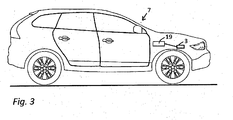
- Fig. 3 illustrates a vehicle alarm system 19 comprising a sounder device 3 according to some embodiments. Also, Fig. 3 illustrates a vehicle 7. The vehicle 7 comprises a vehicle alarm system 19 according to some embodiments.
- the common abbreviation "e.g.” which derives from the Latin phrase “exempli gratia,” may be used to introduce or specify a general example or examples of a previously mentioned item, and is not intended to be limiting of such item. If used herein, the common abbreviation “ i.e .”, which derives from the Latin phrase “id est,” may be used to specify a particular item from a more general recitation.
Landscapes
- Physics & Mathematics (AREA)
- Engineering & Computer Science (AREA)
- Health & Medical Sciences (AREA)
- Otolaryngology (AREA)
- Acoustics & Sound (AREA)
- Signal Processing (AREA)
- Mechanical Engineering (AREA)
- Electromagnetism (AREA)
- General Physics & Mathematics (AREA)
- Alarm Systems (AREA)
- Burglar Alarm Systems (AREA)
Claims (9)
- Fahrzeugalarmsystem-Schallerzeugungsvorrichtung (3), umfassend ein erstes Umformerelement (1) und eine erste Schallerzeugungsoberfläche (11), wobei das erste Umformerelement (1) in Verbindung mit der ersten Schallerzeugungsoberfläche (11) angeordnet ist, um dadurch einen Alarmton (10) auf ein erstes Signal, das von einer Steuervorrichtung (5) gesandt wird, zu erzeugen, die Schallerzeugungsvorrichtung (3) umfassend ein zweites Umformerelement (2), das in Verbindung mit der ersten Schallerzeugungsoberfläche (11) oder einer zweiten Schallerzeugungsoberfläche (12) der Schallerzeugungsvorrichtung (3) angeordnet ist, um dadurch einen Anzeigeton (20), der von dem Alarmton (10) verschieden ist, auf ein zweites Signal, das von der Steuervorrichtung (5) gesandt wird, zu erzeugen, wobei die Schallerzeugungsvorrichtung (3) ein Umformeransteuerelement (16) umfasst, dadurch gekennzeichnet, dass die Schallerzeugungsvorrichtung (3) einen Schalter (14) mit mindestens einer ersten Position und einer zweiten Position umfasst, wobei die erste Position eine Position bildet, in der eine elektrische Verbindung zwischen dem Umformeransteuerelement (16) und dem ersten Umformerelement (1) geschlossen ist, und die zweite Position eine Position bildet, in der eine elektrische Verbindung zwischen dem Umformeransteuerelement (16) und dem zweiten Umformerelement (2) geschlossen ist, wobei die Steuervorrichtung (5) eine Mikrosteuerung (5) ist, angeordnet zum Steuern des Schalters (14) zwischen der ersten und der zweiten Position, wobei das Umformeransteuerelement (16) angepasst ist, das erste und das zweite Signal, die von der Steuervorrichtung (5) gesandt werden, zu empfangen, und angepasst ist, ein erstes Ausgangssignal zu erzeugen, wenn das erste Signal empfangen wird, und ein zweites Ausgangssignal zu erzeugen, wenn das zweite Signal empfangen wird, wobei das erste Umformerelement (1) angepasst ist, den Alarmton (10) zu erzeugen, nachdem ihm das erste Ausgangssignal zugeführt wurde, und wobei das zweite Umformerelement (2) angepasst ist, den Anzeigeton (20) zu erzeugen, nachdem ihm das zweite Ausgangssignal zugeführt wurde.
- Schallerzeugungsvorrichtung (3) nach Anspruch 1, dadurch gekennzeichnet, dass die Schallerzeugungsvorrichtung (3) eine oder mehrere Batterien (17) umfasst, die angeordnet sind, der Mikrosteuerung (5) und dem Umformeransteuerelement (16) elektrischen Strom zuzuführen.
- Schallerzeugungsvorrichtung (3) nach Anspruch 1 oder 2, dadurch gekennzeichnet, dass das erste Umformerelement (1) ein erstes Piezo-Element ist.
- Schallerzeugungsvorrichtung (3) nach einem der vorstehenden Ansprüche, dadurch gekennzeichnet, dass das zweite Umformerelement (2) ein zweites Piezo-Element ist.
- Fahrzeugalarmsystem (19), dadurch gekennzeichnet, dass es eine Schallerzeugungsvorrichtung (3) nach einem der vorstehenden Ansprüche umfasst.
- Fahrzeug (7), dadurch gekennzeichnet, dass das Fahrzeug (7) ein Fahrzeugalarmsystem (19) nach Anspruch 5 umfasst.
- Fahrzeug (7) nach Anspruch 6, wobei der Anzeigeton (20) einen Anzeigeton (20) bildet, der anzeigt, dass der Fahrer das Fahrzeug (7) verlässt oder im Begriff ist, es zu verlassen, während eine Antriebseinheit aktiv ist.
- Fahrzeug (7) nach Anspruch 6 oder 7, wobei der Anzeigeton (20) einen Anzeigeton (20) bildet, der anzeigt, dass der Fahrer das Fahrzeug (7) verlässt oder im Begriff ist, es zu verlassen, während ein Schlüssel in einem Schlüsselschalter zum Aktivieren einer Antriebseinheit angeordnet ist.
- Fahrzeug (7) nach einem der Ansprüche 6-8, wobei das Fahrzeug (7) mindestens teilweise von einem elektrischen Motor angetrieben wird und der Anzeigeton (20) einen Anzeigeton (20) bildet, der eine Präsenz des Fahrzeugs (7) anzeigt.
Priority Applications (1)
| Application Number | Priority Date | Filing Date | Title |
|---|---|---|---|
| EP12163123.8A EP2648420B1 (de) | 2012-04-04 | 2012-04-04 | Summervorrichtung für Fahrzeugalarmsystem |
Applications Claiming Priority (1)
| Application Number | Priority Date | Filing Date | Title |
|---|---|---|---|
| EP12163123.8A EP2648420B1 (de) | 2012-04-04 | 2012-04-04 | Summervorrichtung für Fahrzeugalarmsystem |
Publications (2)
| Publication Number | Publication Date |
|---|---|
| EP2648420A1 EP2648420A1 (de) | 2013-10-09 |
| EP2648420B1 true EP2648420B1 (de) | 2016-10-12 |
Family
ID=46025452
Family Applications (1)
| Application Number | Title | Priority Date | Filing Date |
|---|---|---|---|
| EP12163123.8A Active EP2648420B1 (de) | 2012-04-04 | 2012-04-04 | Summervorrichtung für Fahrzeugalarmsystem |
Country Status (1)
| Country | Link |
|---|---|
| EP (1) | EP2648420B1 (de) |
Families Citing this family (1)
| Publication number | Priority date | Publication date | Assignee | Title |
|---|---|---|---|---|
| DE102021105501A1 (de) * | 2021-03-08 | 2022-09-08 | Dr. Ing. H.C. F. Porsche Aktiengesellschaft | Fahrzeug mit einem Luftleitelement und Verfahren zum Verstellen eines Luftleitelements an einem Fahrzeug |
Family Cites Families (4)
| Publication number | Priority date | Publication date | Assignee | Title |
|---|---|---|---|---|
| JPS5651640A (en) * | 1979-10-04 | 1981-05-09 | Nissan Motor Co Ltd | Sound information transfer system for car |
| DE3828634A1 (de) * | 1988-08-24 | 1989-06-29 | Daimler Benz Ag | Akustische informations- und warnvorrichtung in einem fahrzeug |
| JP5514221B2 (ja) * | 2010-02-23 | 2014-06-04 | パナソニック株式会社 | 圧電型音響変換器 |
| CN201898590U (zh) * | 2010-12-07 | 2011-07-13 | 瑞声光电科技(常州)有限公司 | 发声器装置 |
-
2012
- 2012-04-04 EP EP12163123.8A patent/EP2648420B1/de active Active
Also Published As
| Publication number | Publication date |
|---|---|
| EP2648420A1 (de) | 2013-10-09 |
Similar Documents
| Publication | Publication Date | Title |
|---|---|---|
| US9734699B2 (en) | System for providing alerts to vehicle occupants | |
| US9536401B2 (en) | Systems and methods for indicating the presence of a mobile device within a passenger cabin | |
| CN105916743B (zh) | 断开检测装置 | |
| US9789850B2 (en) | Disconnection detection device | |
| CN110194124A (zh) | 车辆被动远程无钥匙进入和用于提供智能钥匙警报的方法 | |
| EP2648420B1 (de) | Summervorrichtung für Fahrzeugalarmsystem | |
| JP2014015186A (ja) | 車両存在通報装置 | |
| CA2974521C (en) | Vehicle system including security unit providing degradation commands via a vehicle data bus and related methods | |
| US20160083003A1 (en) | Vehicle securing system | |
| CN112449292B (zh) | 用于汽车传声器应用的压电隔膜换能器的系统和方法 | |
| WO2014024333A1 (ja) | 車両用ホーン装置 | |
| CN102452429A (zh) | 一种电动车报警装置 | |
| JP2010254052A (ja) | 車両用警報装置 | |
| CN204037732U (zh) | 一种电动车蓄电池防盗报警装置 | |
| JP6410770B2 (ja) | 自転車用通信装置および自転車用衝突予防システム | |
| CA3062636A1 (en) | Vehicle system including remote start data bus command sending based upon a short-range link and related methods | |
| CN218661733U (zh) | 车辆防盗系统和车辆 | |
| JP2014166811A (ja) | 車両盗難防止装置 | |
| US20210225157A1 (en) | Smart Relay Car Alarm System | |
| CN202110282U (zh) | 智能新型倒车雷达 | |
| US20190349698A1 (en) | Speaker operation confirmation device | |
| JP2008105527A (ja) | 車両用警報装置 | |
| JP2015016720A (ja) | 盗難防止システム | |
| JP2021004010A (ja) | ホーン制御装置 | |
| KR20050120983A (ko) | 차량용 경보 시스템 및 그 방법 |
Legal Events
| Date | Code | Title | Description |
|---|---|---|---|
| PUAI | Public reference made under article 153(3) epc to a published international application that has entered the european phase |
Free format text: ORIGINAL CODE: 0009012 |
|
| AK | Designated contracting states |
Kind code of ref document: A1 Designated state(s): AL AT BE BG CH CY CZ DE DK EE ES FI FR GB GR HR HU IE IS IT LI LT LU LV MC MK MT NL NO PL PT RO RS SE SI SK SM TR |
|
| AX | Request for extension of the european patent |
Extension state: BA ME |
|
| 17P | Request for examination filed |
Effective date: 20140409 |
|
| RBV | Designated contracting states (corrected) |
Designated state(s): AL AT BE BG CH CY CZ DE DK EE ES FI FR GB GR HR HU IE IS IT LI LT LU LV MC MK MT NL NO PL PT RO RS SE SI SK SM TR |
|
| 17Q | First examination report despatched |
Effective date: 20140703 |
|
| GRAP | Despatch of communication of intention to grant a patent |
Free format text: ORIGINAL CODE: EPIDOSNIGR1 |
|
| INTG | Intention to grant announced |
Effective date: 20160531 |
|
| GRAS | Grant fee paid |
Free format text: ORIGINAL CODE: EPIDOSNIGR3 |
|
| GRAA | (expected) grant |
Free format text: ORIGINAL CODE: 0009210 |
|
| RIN1 | Information on inventor provided before grant (corrected) |
Inventor name: MAGNUSSON, TOMAS Inventor name: HIRCHE, MARK Inventor name: STURESSON, HENRIK Inventor name: OLSSON, KJELL |
|
| RIN1 | Information on inventor provided before grant (corrected) |
Inventor name: STURESSON, HENRIK Inventor name: OLSSON, KJELL Inventor name: HIRCHE, MARK Inventor name: MAGNUSSON, TOMAS |
|
| AK | Designated contracting states |
Kind code of ref document: B1 Designated state(s): AL AT BE BG CH CY CZ DE DK EE ES FI FR GB GR HR HU IE IS IT LI LT LU LV MC MK MT NL NO PL PT RO RS SE SI SK SM TR |
|
| REG | Reference to a national code |
Ref country code: GB Ref legal event code: FG4D |
|
| REG | Reference to a national code |
Ref country code: CH Ref legal event code: EP |
|
| REG | Reference to a national code |
Ref country code: AT Ref legal event code: REF Ref document number: 837419 Country of ref document: AT Kind code of ref document: T Effective date: 20161015 |
|
| REG | Reference to a national code |
Ref country code: IE Ref legal event code: FG4D |
|
| REG | Reference to a national code |
Ref country code: DE Ref legal event code: R096 Ref document number: 602012023947 Country of ref document: DE |
|
| REG | Reference to a national code |
Ref country code: SE Ref legal event code: TRGR |
|
| REG | Reference to a national code |
Ref country code: LT Ref legal event code: MG4D |
|
| REG | Reference to a national code |
Ref country code: NL Ref legal event code: MP Effective date: 20161012 |
|
| PG25 | Lapsed in a contracting state [announced via postgrant information from national office to epo] |
Ref country code: LV Free format text: LAPSE BECAUSE OF FAILURE TO SUBMIT A TRANSLATION OF THE DESCRIPTION OR TO PAY THE FEE WITHIN THE PRESCRIBED TIME-LIMIT Effective date: 20161012 |
|
| REG | Reference to a national code |
Ref country code: AT Ref legal event code: MK05 Ref document number: 837419 Country of ref document: AT Kind code of ref document: T Effective date: 20161012 |
|
| PG25 | Lapsed in a contracting state [announced via postgrant information from national office to epo] |
Ref country code: GR Free format text: LAPSE BECAUSE OF FAILURE TO SUBMIT A TRANSLATION OF THE DESCRIPTION OR TO PAY THE FEE WITHIN THE PRESCRIBED TIME-LIMIT Effective date: 20170113 Ref country code: NO Free format text: LAPSE BECAUSE OF FAILURE TO SUBMIT A TRANSLATION OF THE DESCRIPTION OR TO PAY THE FEE WITHIN THE PRESCRIBED TIME-LIMIT Effective date: 20170112 Ref country code: LT Free format text: LAPSE BECAUSE OF FAILURE TO SUBMIT A TRANSLATION OF THE DESCRIPTION OR TO PAY THE FEE WITHIN THE PRESCRIBED TIME-LIMIT Effective date: 20161012 |
|
| PG25 | Lapsed in a contracting state [announced via postgrant information from national office to epo] |
Ref country code: AT Free format text: LAPSE BECAUSE OF FAILURE TO SUBMIT A TRANSLATION OF THE DESCRIPTION OR TO PAY THE FEE WITHIN THE PRESCRIBED TIME-LIMIT Effective date: 20161012 Ref country code: NL Free format text: LAPSE BECAUSE OF FAILURE TO SUBMIT A TRANSLATION OF THE DESCRIPTION OR TO PAY THE FEE WITHIN THE PRESCRIBED TIME-LIMIT Effective date: 20161012 Ref country code: RS Free format text: LAPSE BECAUSE OF FAILURE TO SUBMIT A TRANSLATION OF THE DESCRIPTION OR TO PAY THE FEE WITHIN THE PRESCRIBED TIME-LIMIT Effective date: 20161012 Ref country code: IS Free format text: LAPSE BECAUSE OF FAILURE TO SUBMIT A TRANSLATION OF THE DESCRIPTION OR TO PAY THE FEE WITHIN THE PRESCRIBED TIME-LIMIT Effective date: 20170212 Ref country code: FI Free format text: LAPSE BECAUSE OF FAILURE TO SUBMIT A TRANSLATION OF THE DESCRIPTION OR TO PAY THE FEE WITHIN THE PRESCRIBED TIME-LIMIT Effective date: 20161012 Ref country code: HR Free format text: LAPSE BECAUSE OF FAILURE TO SUBMIT A TRANSLATION OF THE DESCRIPTION OR TO PAY THE FEE WITHIN THE PRESCRIBED TIME-LIMIT Effective date: 20161012 Ref country code: PT Free format text: LAPSE BECAUSE OF FAILURE TO SUBMIT A TRANSLATION OF THE DESCRIPTION OR TO PAY THE FEE WITHIN THE PRESCRIBED TIME-LIMIT Effective date: 20170213 Ref country code: PL Free format text: LAPSE BECAUSE OF FAILURE TO SUBMIT A TRANSLATION OF THE DESCRIPTION OR TO PAY THE FEE WITHIN THE PRESCRIBED TIME-LIMIT Effective date: 20161012 Ref country code: ES Free format text: LAPSE BECAUSE OF FAILURE TO SUBMIT A TRANSLATION OF THE DESCRIPTION OR TO PAY THE FEE WITHIN THE PRESCRIBED TIME-LIMIT Effective date: 20161012 Ref country code: BE Free format text: LAPSE BECAUSE OF FAILURE TO SUBMIT A TRANSLATION OF THE DESCRIPTION OR TO PAY THE FEE WITHIN THE PRESCRIBED TIME-LIMIT Effective date: 20161012 |
|
| REG | Reference to a national code |
Ref country code: DE Ref legal event code: R097 Ref document number: 602012023947 Country of ref document: DE |
|
| PG25 | Lapsed in a contracting state [announced via postgrant information from national office to epo] |
Ref country code: DK Free format text: LAPSE BECAUSE OF FAILURE TO SUBMIT A TRANSLATION OF THE DESCRIPTION OR TO PAY THE FEE WITHIN THE PRESCRIBED TIME-LIMIT Effective date: 20161012 Ref country code: RO Free format text: LAPSE BECAUSE OF FAILURE TO SUBMIT A TRANSLATION OF THE DESCRIPTION OR TO PAY THE FEE WITHIN THE PRESCRIBED TIME-LIMIT Effective date: 20161012 Ref country code: EE Free format text: LAPSE BECAUSE OF FAILURE TO SUBMIT A TRANSLATION OF THE DESCRIPTION OR TO PAY THE FEE WITHIN THE PRESCRIBED TIME-LIMIT Effective date: 20161012 Ref country code: CZ Free format text: LAPSE BECAUSE OF FAILURE TO SUBMIT A TRANSLATION OF THE DESCRIPTION OR TO PAY THE FEE WITHIN THE PRESCRIBED TIME-LIMIT Effective date: 20161012 Ref country code: SK Free format text: LAPSE BECAUSE OF FAILURE TO SUBMIT A TRANSLATION OF THE DESCRIPTION OR TO PAY THE FEE WITHIN THE PRESCRIBED TIME-LIMIT Effective date: 20161012 |
|
| PLBE | No opposition filed within time limit |
Free format text: ORIGINAL CODE: 0009261 |
|
| STAA | Information on the status of an ep patent application or granted ep patent |
Free format text: STATUS: NO OPPOSITION FILED WITHIN TIME LIMIT |
|
| PG25 | Lapsed in a contracting state [announced via postgrant information from national office to epo] |
Ref country code: SM Free format text: LAPSE BECAUSE OF FAILURE TO SUBMIT A TRANSLATION OF THE DESCRIPTION OR TO PAY THE FEE WITHIN THE PRESCRIBED TIME-LIMIT Effective date: 20161012 Ref country code: IT Free format text: LAPSE BECAUSE OF FAILURE TO SUBMIT A TRANSLATION OF THE DESCRIPTION OR TO PAY THE FEE WITHIN THE PRESCRIBED TIME-LIMIT Effective date: 20161012 Ref country code: BG Free format text: LAPSE BECAUSE OF FAILURE TO SUBMIT A TRANSLATION OF THE DESCRIPTION OR TO PAY THE FEE WITHIN THE PRESCRIBED TIME-LIMIT Effective date: 20170112 |
|
| 26N | No opposition filed |
Effective date: 20170713 |
|
| PG25 | Lapsed in a contracting state [announced via postgrant information from national office to epo] |
Ref country code: SI Free format text: LAPSE BECAUSE OF FAILURE TO SUBMIT A TRANSLATION OF THE DESCRIPTION OR TO PAY THE FEE WITHIN THE PRESCRIBED TIME-LIMIT Effective date: 20161012 |
|
| REG | Reference to a national code |
Ref country code: CH Ref legal event code: PL |
|
| REG | Reference to a national code |
Ref country code: IE Ref legal event code: MM4A |
|
| REG | Reference to a national code |
Ref country code: FR Ref legal event code: ST Effective date: 20171229 |
|
| PG25 | Lapsed in a contracting state [announced via postgrant information from national office to epo] |
Ref country code: MC Free format text: LAPSE BECAUSE OF FAILURE TO SUBMIT A TRANSLATION OF THE DESCRIPTION OR TO PAY THE FEE WITHIN THE PRESCRIBED TIME-LIMIT Effective date: 20161012 Ref country code: FR Free format text: LAPSE BECAUSE OF NON-PAYMENT OF DUE FEES Effective date: 20170502 |
|
| PG25 | Lapsed in a contracting state [announced via postgrant information from national office to epo] |
Ref country code: LU Free format text: LAPSE BECAUSE OF NON-PAYMENT OF DUE FEES Effective date: 20170404 Ref country code: LI Free format text: LAPSE BECAUSE OF NON-PAYMENT OF DUE FEES Effective date: 20170430 Ref country code: CH Free format text: LAPSE BECAUSE OF NON-PAYMENT OF DUE FEES Effective date: 20170430 |
|
| PG25 | Lapsed in a contracting state [announced via postgrant information from national office to epo] |
Ref country code: IE Free format text: LAPSE BECAUSE OF NON-PAYMENT OF DUE FEES Effective date: 20170404 |
|
| PG25 | Lapsed in a contracting state [announced via postgrant information from national office to epo] |
Ref country code: MT Free format text: LAPSE BECAUSE OF NON-PAYMENT OF DUE FEES Effective date: 20170404 |
|
| PG25 | Lapsed in a contracting state [announced via postgrant information from national office to epo] |
Ref country code: HU Free format text: LAPSE BECAUSE OF FAILURE TO SUBMIT A TRANSLATION OF THE DESCRIPTION OR TO PAY THE FEE WITHIN THE PRESCRIBED TIME-LIMIT; INVALID AB INITIO Effective date: 20120404 |
|
| PGFP | Annual fee paid to national office [announced via postgrant information from national office to epo] |
Ref country code: SE Payment date: 20190416 Year of fee payment: 8 |
|
| PG25 | Lapsed in a contracting state [announced via postgrant information from national office to epo] |
Ref country code: CY Free format text: LAPSE BECAUSE OF NON-PAYMENT OF DUE FEES Effective date: 20161012 |
|
| PGFP | Annual fee paid to national office [announced via postgrant information from national office to epo] |
Ref country code: GB Payment date: 20190408 Year of fee payment: 8 |
|
| PG25 | Lapsed in a contracting state [announced via postgrant information from national office to epo] |
Ref country code: MK Free format text: LAPSE BECAUSE OF FAILURE TO SUBMIT A TRANSLATION OF THE DESCRIPTION OR TO PAY THE FEE WITHIN THE PRESCRIBED TIME-LIMIT Effective date: 20161012 |
|
| PG25 | Lapsed in a contracting state [announced via postgrant information from national office to epo] |
Ref country code: TR Free format text: LAPSE BECAUSE OF FAILURE TO SUBMIT A TRANSLATION OF THE DESCRIPTION OR TO PAY THE FEE WITHIN THE PRESCRIBED TIME-LIMIT Effective date: 20161012 |
|
| PG25 | Lapsed in a contracting state [announced via postgrant information from national office to epo] |
Ref country code: AL Free format text: LAPSE BECAUSE OF FAILURE TO SUBMIT A TRANSLATION OF THE DESCRIPTION OR TO PAY THE FEE WITHIN THE PRESCRIBED TIME-LIMIT Effective date: 20161012 |
|
| PG25 | Lapsed in a contracting state [announced via postgrant information from national office to epo] |
Ref country code: SE Free format text: LAPSE BECAUSE OF NON-PAYMENT OF DUE FEES Effective date: 20200405 |
|
| GBPC | Gb: european patent ceased through non-payment of renewal fee |
Effective date: 20200404 |
|
| PG25 | Lapsed in a contracting state [announced via postgrant information from national office to epo] |
Ref country code: GB Free format text: LAPSE BECAUSE OF NON-PAYMENT OF DUE FEES Effective date: 20200404 |
|
| P01 | Opt-out of the competence of the unified patent court (upc) registered |
Effective date: 20231212 |
|
| PGFP | Annual fee paid to national office [announced via postgrant information from national office to epo] |
Ref country code: DE Payment date: 20250319 Year of fee payment: 14 |