EP2648800B1 - Recharge électrique portable de dispositifs médicaux implantables - Google Patents
Recharge électrique portable de dispositifs médicaux implantables Download PDFInfo
- Publication number
- EP2648800B1 EP2648800B1 EP11846832.1A EP11846832A EP2648800B1 EP 2648800 B1 EP2648800 B1 EP 2648800B1 EP 11846832 A EP11846832 A EP 11846832A EP 2648800 B1 EP2648800 B1 EP 2648800B1
- Authority
- EP
- European Patent Office
- Prior art keywords
- charger
- power supply
- rechargeable
- implantable
- external
- Prior art date
- Legal status (The legal status is an assumption and is not a legal conclusion. Google has not performed a legal analysis and makes no representation as to the accuracy of the status listed.)
- Active
Links
Images



Classifications
-
- A—HUMAN NECESSITIES
- A61—MEDICAL OR VETERINARY SCIENCE; HYGIENE
- A61N—ELECTROTHERAPY; MAGNETOTHERAPY; RADIATION THERAPY; ULTRASOUND THERAPY
- A61N1/00—Electrotherapy; Circuits therefor
- A61N1/18—Applying electric currents by contact electrodes
- A61N1/32—Applying electric currents by contact electrodes alternating or intermittent currents
- A61N1/36—Applying electric currents by contact electrodes alternating or intermittent currents for stimulation
- A61N1/372—Arrangements in connection with the implantation of stimulators
- A61N1/378—Electrical supply
- A61N1/3787—Electrical supply from an external energy source
-
- A—HUMAN NECESSITIES
- A61—MEDICAL OR VETERINARY SCIENCE; HYGIENE
- A61N—ELECTROTHERAPY; MAGNETOTHERAPY; RADIATION THERAPY; ULTRASOUND THERAPY
- A61N1/00—Electrotherapy; Circuits therefor
- A61N1/18—Applying electric currents by contact electrodes
- A61N1/32—Applying electric currents by contact electrodes alternating or intermittent currents
- A61N1/36—Applying electric currents by contact electrodes alternating or intermittent currents for stimulation
- A61N1/372—Arrangements in connection with the implantation of stimulators
- A61N1/37211—Means for communicating with stimulators
- A61N1/37217—Means for communicating with stimulators characterised by the communication link, e.g. acoustic or tactile
-
- A—HUMAN NECESSITIES
- A61—MEDICAL OR VETERINARY SCIENCE; HYGIENE
- A61N—ELECTROTHERAPY; MAGNETOTHERAPY; RADIATION THERAPY; ULTRASOUND THERAPY
- A61N1/00—Electrotherapy; Circuits therefor
- A61N1/18—Applying electric currents by contact electrodes
- A61N1/32—Applying electric currents by contact electrodes alternating or intermittent currents
- A61N1/36—Applying electric currents by contact electrodes alternating or intermittent currents for stimulation
- A61N1/372—Arrangements in connection with the implantation of stimulators
- A61N1/37211—Means for communicating with stimulators
- A61N1/37217—Means for communicating with stimulators characterised by the communication link, e.g. acoustic or tactile
- A61N1/37223—Circuits for electromagnetic coupling
-
- H—ELECTRICITY
- H02—GENERATION; CONVERSION OR DISTRIBUTION OF ELECTRIC POWER
- H02J—ELECTRIC POWER NETWORKS; CIRCUIT ARRANGEMENTS OR SYSTEMS FOR SUPPLYING OR DISTRIBUTING ELECTRIC POWER; SYSTEMS FOR STORING ELECTRIC ENERGY
- H02J50/00—Circuit arrangements or systems for wireless supply or distribution of electric power
- H02J50/10—Circuit arrangements or systems for wireless supply or distribution of electric power using inductive coupling
-
- H—ELECTRICITY
- H02—GENERATION; CONVERSION OR DISTRIBUTION OF ELECTRIC POWER
- H02J—ELECTRIC POWER NETWORKS; CIRCUIT ARRANGEMENTS OR SYSTEMS FOR SUPPLYING OR DISTRIBUTING ELECTRIC POWER; SYSTEMS FOR STORING ELECTRIC ENERGY
- H02J50/00—Circuit arrangements or systems for wireless supply or distribution of electric power
- H02J50/40—Circuit arrangements or systems for wireless supply or distribution of electric power using two or more transmitting or receiving devices
- H02J50/402—Circuit arrangements or systems for wireless supply or distribution of electric power using two or more transmitting or receiving devices the two or more transmitting or the two or more receiving devices being integrated in the same unit, e.g. power mats with several coils or antennas with several sub-antennas
-
- H—ELECTRICITY
- H02—GENERATION; CONVERSION OR DISTRIBUTION OF ELECTRIC POWER
- H02J—ELECTRIC POWER NETWORKS; CIRCUIT ARRANGEMENTS OR SYSTEMS FOR SUPPLYING OR DISTRIBUTING ELECTRIC POWER; SYSTEMS FOR STORING ELECTRIC ENERGY
- H02J50/00—Circuit arrangements or systems for wireless supply or distribution of electric power
- H02J50/80—Circuit arrangements or systems for wireless supply or distribution of electric power involving the exchange of data, concerning supply or distribution of electric power, between transmitting devices and receiving devices
-
- H—ELECTRICITY
- H02—GENERATION; CONVERSION OR DISTRIBUTION OF ELECTRIC POWER
- H02J—ELECTRIC POWER NETWORKS; CIRCUIT ARRANGEMENTS OR SYSTEMS FOR SUPPLYING OR DISTRIBUTING ELECTRIC POWER; SYSTEMS FOR STORING ELECTRIC ENERGY
- H02J50/00—Circuit arrangements or systems for wireless supply or distribution of electric power
- H02J50/90—Circuit arrangements or systems for wireless supply or distribution of electric power involving detection or optimisation of position, e.g. alignment
-
- H—ELECTRICITY
- H02—GENERATION; CONVERSION OR DISTRIBUTION OF ELECTRIC POWER
- H02J—ELECTRIC POWER NETWORKS; CIRCUIT ARRANGEMENTS OR SYSTEMS FOR SUPPLYING OR DISTRIBUTING ELECTRIC POWER; SYSTEMS FOR STORING ELECTRIC ENERGY
- H02J7/00—Circuit arrangements for charging or discharging batteries or for supplying loads from batteries
- H02J7/40—Circuit arrangements for charging or discharging batteries or for supplying loads from batteries characterised by the exchange of charge or discharge related data
- H02J7/42—Circuit arrangements for charging or discharging batteries or for supplying loads from batteries characterised by the exchange of charge or discharge related data with electronic devices having internal batteries, e.g. mobile phones
-
- A—HUMAN NECESSITIES
- A61—MEDICAL OR VETERINARY SCIENCE; HYGIENE
- A61N—ELECTROTHERAPY; MAGNETOTHERAPY; RADIATION THERAPY; ULTRASOUND THERAPY
- A61N1/00—Electrotherapy; Circuits therefor
- A61N1/18—Applying electric currents by contact electrodes
- A61N1/32—Applying electric currents by contact electrodes alternating or intermittent currents
- A61N1/36—Applying electric currents by contact electrodes alternating or intermittent currents for stimulation
- A61N1/36036—Applying electric currents by contact electrodes alternating or intermittent currents for stimulation of the outer, middle or inner ear
- A61N1/36038—Cochlear stimulation
-
- H—ELECTRICITY
- H02—GENERATION; CONVERSION OR DISTRIBUTION OF ELECTRIC POWER
- H02J—ELECTRIC POWER NETWORKS; CIRCUIT ARRANGEMENTS OR SYSTEMS FOR SUPPLYING OR DISTRIBUTING ELECTRIC POWER; SYSTEMS FOR STORING ELECTRIC ENERGY
- H02J2105/00—Networks for supplying or distributing electric power characterised by their spatial reach or by the load
- H02J2105/40—Networks for supplying or distributing electric power characterised by their spatial reach or by the load characterised by the loads connecting to the networks or being supplied by the networks
- H02J2105/46—Medical devices, medical implants or life supporting devices
-
- H—ELECTRICITY
- H04—ELECTRIC COMMUNICATION TECHNIQUE
- H04R—LOUDSPEAKERS, MICROPHONES, GRAMOPHONE PICK-UPS OR LIKE ACOUSTIC ELECTROMECHANICAL TRANSDUCERS; ELECTRIC HEARING AIDS; PUBLIC ADDRESS SYSTEMS
- H04R2225/00—Details of deaf aids covered by H04R25/00, not provided for in any of its subgroups
- H04R2225/31—Aspects of the use of accumulators in hearing aids, e.g. rechargeable batteries or fuel cells
-
- H—ELECTRICITY
- H04—ELECTRIC COMMUNICATION TECHNIQUE
- H04R—LOUDSPEAKERS, MICROPHONES, GRAMOPHONE PICK-UPS OR LIKE ACOUSTIC ELECTROMECHANICAL TRANSDUCERS; ELECTRIC HEARING AIDS; PUBLIC ADDRESS SYSTEMS
- H04R2225/00—Details of deaf aids covered by H04R25/00, not provided for in any of its subgroups
- H04R2225/67—Implantable hearing aids or parts thereof not covered by H04R25/606
Definitions
- the present invention relates generally to implantable medical devices, and more particularly, to portable power charging of implantable medical devices.
- Implantable medical devices provide a wide range of therapeutic benefits to recipients.
- Certain implantable medical devices sometimes referred to as active implantable medical devices (AIMDs)
- AIMDs include an implantable power supply that provides power to one or more implantable components.
- AIMDS include, but are not limited to, certain implantable hearing prostheses, neural stimulators, drug pumps and cardiac devices.
- partially implantable cochlear implants consist of an external speech processor unit and an implanted receiver/stimulator unit.
- the external speech processor unit is worn on the body of the user, such as a behind-the-ear (BTE) device.
- BTE devices are generally configured to receive sound with a sound input element, such as a microphone, and to convert the received sound into an electrically coded data signal that is transcutaneously transferred to the implanted receiver/stimulator unit.
- the BTE device is also generally configured to transcutaneoulsy transfer power to the implanted receiver and stimulator unit. More particularly, the power and data are transcutaneously transferred via a magnetic induction link established in a reactive near-field between an external coil closely coupled to an implanted coil.
- the operating power for the BTE device and implanted components is provided by batteries, such as Zn-Air batteries, housed in the device.
- the closely coupled coils include an external coil coupled to the BTE device which is configured to be placed in close proximity to the coil of the implanted component.
- implantable hearing prosthesis and other AIMDs it has become more common for implantable hearing prosthesis and other AIMDs to include an implantable power supply that is sufficient to allow for periods of operation without access to an external power source.
- implantable power storage has enabled certain devices, in particular hearing prostheses, to become totally or fully implantable.
- totally implantable hearing prostheses also have one or more components that were traditionally external to the recipient, such as the sound processor, implantable in the recipient. Accordingly, totally implantable prostheses to operate independently (that is, without an external device) for periods of time. It would be appreciated that, as used herein, totally or fully implantable hearing prosthesis may include external devices such as microphones, remote controls, etc.
- United States patent application US 2010/0046778 A1 relates to an integrated cochlear implant headpiece with a rechargeable battery and a transmitter antenna which transmits energy from the battery to an implanted electronic device.
- the rechargeable battery may be recharged through the transmitter antenna when the integrated headpiece is not in use.
- US 6,275,737 B1 relates to a transcutaneous transmission pouch.
- This document discloses an implanted device with a rechargeable battery and an external portion with a rechargeable battery and a transmission coil which transmits energy from the external portion to the implanted device.
- This document further discloses a charging cradle with which the external portion can be recharged.
- an implantable medical system is provided as set forth in claim 1.
- a method for operating a cochlear implant in another aspect of the present invention, a method for operating a cochlear implant.
- a cochlear implant comprises: an implantable component having a rechargeable power supply; an external auxiliary charger; and an external wireless charger having a rechargeable power supply, and an inductive coil configured to transcutaneously transfer power from the charger power supply to the implantable power supply, and configured to detect and receive, via the inductive coil, power from the auxiliary charger for recharging of the charger power supply.
- aspects of the present invention are generally directed to an implantable medical device or system having an implantable power supply that receives power from wireless charger worn by a recipient of the device.
- the wireless charger also includes a rechargeable power supply, and is configured to transcutaneously transfer power to the implantable power supply.
- the wireless charger is also configured to receive power from an auxiliary charger.
- the wireless charger includes one inductive coil that is used to both receive and transmit power.
- Embodiments of the present invention will be described with reference to a particular illustrative implantable medical system, namely a cochlear implant system, commonly referred to as a cochlear prosthesis or simply cochlear implant. It would be appreciated that embodiments of the present invention may be implemented in other medical systems utilizing or requiring periodic transfer of power via an indicative link. Exemplary devices include, but are not limited to, neural or muscle stimulators, drug pumps, cardiac devices, and other hearing prosthesis such as hybrid electrical/acoustic systems, acoustic hearing aid systems, middle ear stimulators, or fully external hearing systems, etc.
- FIG. 1A is a schematic diagram of a cochlear implant 100 in accordance with embodiments of the present invention.
- cochlear implant 100 comprises an implantable component 104 positioned below a recipient's skin and other tissue (not shown), and external component(s) 102.
- external component(s) 102 comprise a wireless charger 110, and an external accessory 106. Further details of wireless charger 110 and external accessory 106 are provided below.
- wireless charger 110 includes to a radio frequency (RF) headpiece coil 112.
- Headpiece coil 112 is configured to be inductively coupled to RF coil 116 in implantable component 104 via inductive link 132.
- Implantable coil 116 is connected to a transceiver unit 128.
- implantable component 104 also includes an implantable power supply, shown as a rechargeable battery unit 118, a stimulator unit 120, an intracochlear electrode assembly 122 and one or more supplementary extracochlear ground electrode(s) 124.
- implantable power supply shown as a rechargeable battery unit 118
- a stimulator unit 120 an intracochlear electrode assembly 122
- one or more supplementary extracochlear ground electrode(s) 124 are positioned in a hermetically sealed housing 130.
- Implantable component 104 also includes an electronics module 102 that may comprise, for example, a sound processor, memory, controller, etc.
- Microphone 126 may be electrically coupled to one or more components in housing 130 via a cable/lead, or via a wireless link 144.
- wireless charger 110 includes a rechargeable power supply, sometimes referred to herein as charger power supply or battery system 134.
- battery system 134 comprises one or more rechargeable batteries 134.
- any rechargeable power source that is able is sufficiently small and is able to fulfill the power requirements of the device may be used.
- a Li-ion or Li-polymer battery unit is used. As is known in the art, such batteries may be shaped to fit perfectly in housings having different geometries.
- nickel cadmium, metal hydride, a supercapacitor based system or even energy stored in a spring wound up by a clockwork mechanism may be used.
- Wireless charger 110 is configured to provide power from battery system 134 to implantable battery unit 118. The power is inductively transferred via link 132. As described further below, battery system 134 of wireless charger 110 is recharged by receiving power from an auxiliary charger via headpiece coil 112.
- an external accessory 106 may also be worn by the recipient and may communicate with implantable component 104.
- an external accessory 106 is a device that communicates with implantable component 104 via a low-power wireless data link 140.
- an external accessory 106 includes a microphone and/or sound processor.
- Exemplary external accessories 106 are schematically shown in FIG. 1B as a mini-BTE (106A), micro-BTE (106B), in-the-ear (ITE) device (106C), an in-the-canal (ITC) device (106D), open-fit or over-the-ear device (OTE) (not shown), or other device.
- FIG. 9A is a perspective view of a wireless charger 910A that is a BTE device.
- FIG. 9B is a perspective view of a body worn charger 910B.
- FIG. 1A illustrates embodiments of the present invention in which wireless charger 110 and external accessory 106 are separate components. It would be appreciated that in embodiments of the present invention, external accessory 106 and wireless charger 110 may comprise the same component.
- a BTE device may operate as the wireless charger and may include components of an external accessory, such as a sound processor, microphone etc.
- FIG. 2 is a schematic block diagram of an implementation of a wireless charger 110 of FIG. 1A .
- charger 110 includes a power supply, such as rechargeable battery system 134.
- power from battery system 134 is provided to DC/AC converter 240, that then provides an AC waveform to driver 242.
- the AC waveform may be modulated for transfer of data to implantable component 104 via link 132 ( FIG. 1 ), or if spreading of the frequency spectrum is desired to reduce dense spectral power components (EMC).
- EMC dense spectral power components
- Driver 242 amplifies the waveform to a suitable signal level for power transfer to implantable component 104.
- the amplified signal from driver 242 is provided to routing system 244, which controls the flow of power to and from coil 50.
- routing system 244 is configured to function as a coupler/splitter for signals received from driver 240 and coil 112. Routing system 244 may include components for driving coil 112 to transmit the power signals to implantable component 104.
- coil 112 in wireless charger 110 is used to inductively transfer power to implantable component 104, and to receive power from auxiliary charger 350. Using the same coil for both transmission and receipt of power simplifies the manufacturing process and enhances friendliness and simplicity of use. Accordingly, wireless charger 110 receives power from an auxiliary charger via coil 112 and the received power is routed from the coil to battery recharger 246 and battery system 134.
- FIG. 3 is a perspective view of one implementation of an auxiliary charger 350 in accordance with embodiments of the present invention.
- auxiliary charger 350 comprises a base 352 on which an array of coils 354 is positioned. Attached to base 356 is a plug 356 for connecting auxiliary charger 350 to a 12V power source, DC power supply (e.g. in a car), or other power sources.
- a 12V power source e.g. in a car
- DC power supply e.g. in a car
- FIG. 3 is a perspective view of one implementation of an auxiliary charger 350 in accordance with embodiments of the present invention.
- auxiliary charger 350 comprises a base 352 on which an array of coils 354 is positioned. Attached to base 356 is a plug 356 for connecting auxiliary charger 350 to a 12V power source, DC power supply (e.g. in a car), or other power sources.
- one of the coils 354 is inductively coupled to coil 112.
- the system makes it easier
- auxiliary charger 350 may have a variety of arrangements.
- auxiliary charger 350 may be a charging pad, a cradle, a docking station, or any suitable arrangement.
- Auxiliary charger 350 may also be adapted to charge other devices, for example any externally worn microphone or remote control units.
- FIG. 4 is a schematic diagram illustrating wireless links between auxiliary charger 350, wireless charger 110 and implantable component 104.
- the links shown in FIG. 4 are merely illustrative any additional links could be provided. Alternatively, all of the links shown in FIG. 4 are not necessary and one or more links may be omitted in different configurations.
- a wireless power link 464 is provided between a coil 354 ( FIG. 3 ) in auxiliary charger 350, and headpiece coil 112. Additionally, a feedback link 462 is provided to transmit data information between auxiliary charger 352 and wireless charger 110. For example, link 462 may used by wireless charger 110 to instruct auxiliary charger 350 to adjust link 464, or to adjust other characteristics of the auxiliary charger.
- link 132 is provided between implantable coil 116 and headpiece coil 112 to transmit power from wireless charger 110 to implantable component 104.
- a bidirectional data link 466 may also be provided between coils 112, 116 to transmit data to or from implantable component 104.
- a wireless charger also operates as an external accessory. That is, the wireless charger includes components of an external accessory, such as a sound processor, microphone, control electronics, etc. In such embodiments, an additional data link may be provided between the wireless charger and the implantable component. However, in certain embodiments, the wireless charger is a simple charging arrangement that does not otherwise interact with the implantable component.
- FIG. 5 is schematic diagram of an alternative cochlear implant 500 in accordance with embodiments of the present invention.
- cochlear implant 500 comprises an implantable component 504 that is substantially the same as implantable component 104 of FIG. 1 .
- Cochlear implant 500 further comprises a wireless charger 510.
- wireless charger 510 has a coil 512 wireless charger in its housing 514.
- FIG. 5 Also shown in FIG. 5 are exemplary magnetic flux lines 520 generated by coil. As shown, magnetic flux lines 520 pass through implantable coil 516, thereby inductively coupling coil 512 to coil 516.
- FIG. 3 is a schematic block diagram of one embodiment of wireless charger 110 of FIG. 1 .
- FIG. 6 is a schematic block diagram of an alternative wireless charger 610 having a controller 670 to manage recharging and communications of the charger.
- Charger 610 has components that are substantially the same as described above with reference to FIG. 3 , including batteries 634, DC/AC converter 640, driver 642, routing system 644, and battery recharger 646.
- wireless charger 610 includes several components, namely power detector 672 and controller 670, that are not found in wireless charger 110 of FIG. 3 .
- the power emanating from wireless charger unit 610 is provided to the implantable component 104.
- the auxiliary power emanating from auxiliary charger 350 ( FIG. 3 ) is provided to wireless charger unit 610 to charge the batteries therein or thereon.
- controller 670 will described with reference to the control process 700 of FIG. 7 .
- Control process begins at block 704 after the wireless charger is powered ON at block 702. More particularly, at block 704 controller 670 of wireless charger 610 initially operates the primary power link for a time duration T1.
- the primary power link is the link between external coil 612 of wireless charger 610 and the implantable coil.
- controller 670 disables primary power link for a time duration T2, and monitors for the presence of the auxiliary charger.
- T2 is preferably is relatively short when compared to T1. Referring to the embodiments of FIG. 6 , the presence of the auxiliary charger may be detected by power detector 672. It should be noted that in certain embodiments the primary power link is disabled for a short time at block 706 to allow detection (presence or absence) of auxiliary power sources or implantable components.
- controller 670 performs a check to determine if the auxiliary charger is detected. If the auxiliary charger is not detected, control process 700 returns to block 704 where controller 670 again enables primary power link for T1. This process continues until the auxiliary charger has been detected.
- control process 700 continues to block 710 where controller 670 performs a check of whether the battery is fully charged. If the battery is not fully charged, controller 670 activates the auxiliary link (that is, the link between the wireless charger and the auxiliary charger), and the battery(ies) of the wireless charger are recharged at block 712. If, at block 710, it is determined that the battery(ies) are fully charged, control process 700 returns to block 704. It would be appreciated that control process 700 of FIG. 7 is one implementation, and other methods for managing wireless charger and the dual purpose coil and associated systems may be implemented in alternative embodiments of the present invention
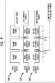
- FIG. 8 is a timing diagram schematically illustrating how certain components of wireless charger 610 are operated during control process 700.
- FIG. 8 shows the output 680A of power detector 672, the input 680B of DC/AC converter 640, and the output 680C of battery recharger 646 during times T1 and T2.
- input 680B of DC/AC converter 640 is high, while output 680C of battery recharger 646 is low (that is, battery recharger 646 is disabled).
- controller 670 monitors for the presence of the auxiliary charger during times T2.
- a wireless backlink 466 from the implantable component 104 to the wireless charger 110 provides the type of implantable component and status information on the state of the implanted rechargeable battery to the recharger during its charging and discharging cycle.
- the wireless back link is optional and could be operating over the same or a different RF frequency channel. In case the RF frequency channel is shared a TDMA scheme becomes necessary. In both cases the system requires additional communication blocks.
- TDMA load modulation could be applied by switching on and off a small load resistance on the BTE charger. This would result in a voltage variation over the auxiliary coil such as in amplitude modulation.
Landscapes
- Engineering & Computer Science (AREA)
- Health & Medical Sciences (AREA)
- Power Engineering (AREA)
- Computer Networks & Wireless Communication (AREA)
- General Health & Medical Sciences (AREA)
- Biomedical Technology (AREA)
- Life Sciences & Earth Sciences (AREA)
- Animal Behavior & Ethology (AREA)
- Nuclear Medicine, Radiotherapy & Molecular Imaging (AREA)
- Public Health (AREA)
- Veterinary Medicine (AREA)
- Radiology & Medical Imaging (AREA)
- Physics & Mathematics (AREA)
- Acoustics & Sound (AREA)
- Electromagnetism (AREA)
- Electrotherapy Devices (AREA)
- Charge And Discharge Circuits For Batteries Or The Like (AREA)
- Prostheses (AREA)
- External Artificial Organs (AREA)
Claims (12)
- Système médical implantable, comprenant:un composant implantable ayant une alimentation électrique implantable rechargeable;un chargeur auxiliaire externe; etun chargeur sans fil externe ayant une alimentation de chargeur rechargeable, et une bobine inductive configurée pour:transférer de manière transcutanée la puissance de l'alimentation du chargeur rechargeable à l'alimentation implantable rechargeable,détecter et recevoir de l'électricité par le biais de la bobine inductive du chargeur auxiliaire externe pour recharger l'alimentation du chargeur rechargeable,caractérisé parun détecteur d'électricité, dans lequel la bobine inductive du chargeur sans fil externe est connectée au détecteur d'électricité, et le détecteur d'électricité est configuré pour détecter au moins l'une de la présence et de l'absence du chargeur auxiliaire externe ou du composant implantable, tandis que la transmission d'électricité de l'alimentation du chargeur rechargeable à l'alimentation implantable rechargeable est désactivée,dans lequel le chargeur auxiliaire externe comprend un réseau de bobines inductives pour le transfert d'électricité au chargeur sans fil externe.
- Système médical implantable selon la revendication 1, dans lequel le chargeur externe sans fil est un dispositif derrière l'oreille (BTE).
- Système médical implantable selon la revendication 1, dans lequel le chargeur externe sans fil est un dispositif porté sur le corps.
- Système médical implantable selon la revendication 1, dans lequel le chargeur externe sans fil a un boîtier, et dans lequel la bobine inductive est séparée du boîtier par un câble; et
intégré dans le boîtier. - Système médical implantable selon la revendication 1, dans lequel une capacité de stockage de l'alimentation électrique du chargeur rechargeable est supérieure à une capacité de stockage de l'alimentation électrique implantable rechargeable.
- Système médical implantable selon la revendication 1, dans lequel le chargeur sans fil externe est adapté pour détecter la présence d'un champ inductif approprié pour recharger l'alimentation électrique du chargeur rechargeable, et en réponse, pour recharger automatiquement l'alimentation électrique du chargeur rechargeable en présence du champ inductif.
- Système médical implantable selon la revendication 1, comprenant en outre:un accessoire externe configuré pour transférer de manière transcutanée des données au composant implantable;dans lequel l'accessoire externe comprend un microphone et un processeur de son; etdans lequel le chargeur sans fil externe est configuré pour fournir de l'électricité à l'accessoire externe par le biais de la bobine inductive.
- Système médical implantable de la revendication 1,
dans lequel le chargeur sans fil externe est en outre configuré pour transférer de manière transcutanée des données vers le composant implantable. - Système médical implantable selon la revendication 1,
dans lequel le chargeur externe sans fil comprend un microphone et un processeur de son. - Procédé pour faire fonctionner un implant cochléaire comprenant un composant implantable ayant une alimentation électrique implantable rechargeable, un chargeur externe sans fil ayant une alimentation électrique de chargeur rechargeable et une bobine inductive, et un chargeur auxiliaire externe comprenant un réseau de bobines inductives de chargeur auxiliaire pour le transfert d'électricité au chargeur externe sans fil, le procédé comprenant:la transmission d'électricité de l'alimentation du chargeur rechargeable à l'alimentation implantable rechargeable avec la bobine inductive;la désactivation de la transmission d'électricité de l'alimentation du chargeur rechargeable à l'alimentation implantable rechargeable; etla vérification d'au moins l'une des deux conditions suivantes: la présence et l'absence du chargeur auxiliaire externe ou du composant implantable, alors que la transmission d'électricité de l'alimentation du chargeur rechargeable à l'alimentation implantable rechargeable est désactivée.
- Procédé selon la revendication 10, comprenant en outre les opérations suivantes:déterminer que le chargeur auxiliaire externe n'est pas présent;répéter les étapes de la revendication 10.
- Procédé selon la revendication 11, comprenant en outre les opérations suivantes:déterminer que le chargeur auxiliaire externe est présent;activer une liaison sans fil entre le chargeur auxiliaire externe et le chargeur externe sans fil;recevoir, avec la bobine inductive, l'électricité du chargeur auxiliaire externe pour recharger l'alimentation électrique du chargeur rechargeable; etdéterminer si l'alimentation du chargeur rechargeable est complètement chargée avant d'activer la liaison sans fil entre le chargeur auxiliaire externe et le chargeur sans fil externe.
Applications Claiming Priority (2)
| Application Number | Priority Date | Filing Date | Title |
|---|---|---|---|
| US12/965,415 US9132276B2 (en) | 2010-12-10 | 2010-12-10 | Portable power charging of implantable medical devices |
| PCT/IB2011/055590 WO2012077088A2 (fr) | 2010-12-10 | 2011-12-09 | Recharge électrique portable de dispositifs médicaux implantables |
Publications (3)
| Publication Number | Publication Date |
|---|---|
| EP2648800A2 EP2648800A2 (fr) | 2013-10-16 |
| EP2648800A4 EP2648800A4 (fr) | 2014-06-18 |
| EP2648800B1 true EP2648800B1 (fr) | 2020-04-08 |
Family
ID=46200128
Family Applications (1)
| Application Number | Title | Priority Date | Filing Date |
|---|---|---|---|
| EP11846832.1A Active EP2648800B1 (fr) | 2010-12-10 | 2011-12-09 | Recharge électrique portable de dispositifs médicaux implantables |
Country Status (4)
| Country | Link |
|---|---|
| US (3) | US9132276B2 (fr) |
| EP (1) | EP2648800B1 (fr) |
| JP (1) | JP6304649B2 (fr) |
| WO (1) | WO2012077088A2 (fr) |
Families Citing this family (99)
| Publication number | Priority date | Publication date | Assignee | Title |
|---|---|---|---|---|
| US8594806B2 (en) | 2010-04-30 | 2013-11-26 | Cyberonics, Inc. | Recharging and communication lead for an implantable device |
| US9132276B2 (en) | 2010-12-10 | 2015-09-15 | Cochlear Limited | Portable power charging of implantable medical devices |
| US10286217B2 (en) | 2011-01-28 | 2019-05-14 | Medtronic, Inc. | Far field telemetry communication with a medical device during a recharge session where a prior pairing with the medical device may not exist |
| US8712541B2 (en) | 2011-01-28 | 2014-04-29 | Medtronic, Inc. | Far field telemetry operations between an external device and an implantable medical device during recharge of the implantable medical device via a proximity coupling |
| US8634927B2 (en) * | 2011-01-28 | 2014-01-21 | Medtronic, Inc. | Medical device recharge systems using a controller in wireless communication with a separate recharge device |
| US8942624B2 (en) | 2012-03-30 | 2015-01-27 | Integrated Device Technology, Inc. | Apparatus, system, and method for back-channel communication in an inductive wireless power transfer system |
| WO2014003777A1 (fr) | 2012-06-29 | 2014-01-03 | Advanced Bionics Ag | Système d'implant cochléaire comprenant une batterie implantable |
| WO2014018971A1 (fr) | 2012-07-27 | 2014-01-30 | Thoratec Corporation | Systèmes de transfert de puissance résonants avec algorithme de protection |
| WO2014018973A1 (fr) | 2012-07-27 | 2014-01-30 | Thoratec Corporation | Bobines et systèmes de transmission de puissance résonants |
| US10383990B2 (en) | 2012-07-27 | 2019-08-20 | Tc1 Llc | Variable capacitor for resonant power transfer systems |
| US9592397B2 (en) | 2012-07-27 | 2017-03-14 | Thoratec Corporation | Thermal management for implantable wireless power transfer systems |
| US10291067B2 (en) | 2012-07-27 | 2019-05-14 | Tc1 Llc | Computer modeling for resonant power transfer systems |
| US9805863B2 (en) | 2012-07-27 | 2017-10-31 | Thoratec Corporation | Magnetic power transmission utilizing phased transmitter coil arrays and phased receiver coil arrays |
| US10525181B2 (en) | 2012-07-27 | 2020-01-07 | Tc1 Llc | Resonant power transfer system and method of estimating system state |
| WO2014018967A1 (fr) | 2012-07-27 | 2014-01-30 | Thoratec Corporation | Systèmes de transfert d'énergie résonnants à accord automatique |
| CN102983637A (zh) * | 2012-09-28 | 2013-03-20 | 河北工业大学 | 小尺寸谐振器以及磁耦合谐振无线能量传输系统 |
| AP2015008452A0 (en) | 2012-10-17 | 2015-05-31 | Transocean Innovation Labs Ltd | Communications systems and methods for subsea processors |
| US9276639B2 (en) | 2013-02-25 | 2016-03-01 | Apple Inc. | Wirelessly charged electronic device with shared inductor circuitry |
| US10373756B2 (en) | 2013-03-15 | 2019-08-06 | Tc1 Llc | Malleable TETs coil with improved anatomical fit |
| WO2014145664A1 (fr) | 2013-03-15 | 2014-09-18 | Thoratec Corporation | Boîtier de test implantable intégré comprenant des ailettes et des boucles de bobine |
| JP2016517730A (ja) * | 2013-04-15 | 2016-06-20 | ティ・オ・ドォッブルビィ・エンジニアリング・アー/エス | 埋込可能部を備えるecgモニタ |
| KR102000513B1 (ko) * | 2013-04-16 | 2019-07-17 | 삼성전자주식회사 | 동작 모드의 스위칭이 가능한 코일을 포함하는 청각 기기 |
| US12373497B1 (en) | 2013-04-30 | 2025-07-29 | Splunk Inc. | Dynamic generation of performance state tree |
| US9155900B2 (en) * | 2013-06-20 | 2015-10-13 | Cochlear Limited | Medical device battery charging system and methods |
| CN105263572B (zh) | 2013-07-29 | 2017-10-17 | 艾尔弗雷德·E·曼科学研究基金会 | 用于植入式装置的高效率磁链路 |
| CA3075310C (fr) | 2013-07-29 | 2022-04-05 | Alfred E. Mann Foundation For Scientific Research | Circuit d'attaque de classe e commande par microprocesseur |
| EP3072210B1 (fr) | 2013-11-11 | 2023-12-20 | Tc1 Llc | Systèmes à communications de transfert de puissance par résonance |
| WO2015070200A1 (fr) | 2013-11-11 | 2015-05-14 | Thoratec Corporation | Systèmes de transfert de puissance par résonance avec communications |
| EP3069358B1 (fr) | 2013-11-11 | 2019-06-12 | Tc1 Llc | Bobine de transfert de puissance résonnante à charnières |
| WO2015095469A1 (fr) * | 2013-12-20 | 2015-06-25 | Med-El Elektromedizinische Geraete Gmbh | Réponse de télémétrie active pour implants auditifs |
| WO2015134871A1 (fr) | 2014-03-06 | 2015-09-11 | Thoratec Corporation | Connecteurs électriques pour dispositifs implantables |
| US9968781B2 (en) | 2014-03-12 | 2018-05-15 | Advanced Bionics Ag | Implantable hearing assistance apparatus and corresponding systems and methods |
| WO2015147772A1 (fr) * | 2014-03-22 | 2015-10-01 | Advanced Bionics Ag | Appareil d'assistance auditive implantable et systèmes et procédés correspondants |
| GB2527075A (en) | 2014-03-17 | 2015-12-16 | Daassist As | Percutaneous system, devices and methods |
| WO2015147773A1 (fr) | 2014-03-22 | 2015-10-01 | Advanced Bionics Ag | Appareil auditif implantable et systèmes et procédés correspondants |
| EP3122421B1 (fr) | 2014-03-22 | 2019-08-07 | Advanced Bionics AG | Systèmes d'aide auditive sans accessoire porté sur la tête |
| WO2015171682A1 (fr) * | 2014-05-06 | 2015-11-12 | The Board Of Trustees Of The University Of Alabama | Système et procédé de transmission d'énergie rf |
| US9855376B2 (en) | 2014-07-25 | 2018-01-02 | Minnetronix, Inc. | Power scaling |
| DE102015112098A1 (de) | 2014-07-25 | 2016-01-28 | Minnetronix, Inc. | Spulenparameter und Steuerung |
| EP3826104B1 (fr) | 2014-09-22 | 2023-05-03 | Tc1 Llc | Conceptions d'antenne de communication entre un implant à alimentation sans fil et un dispositif externe à l'extérieur du corps |
| EP3204989B1 (fr) | 2014-10-06 | 2019-08-21 | Tc1 Llc | Connecteur multiaxial pour dispositifs implantables |
| US10342908B2 (en) | 2015-01-14 | 2019-07-09 | Minnetronix, Inc. | Distributed transformer |
| US10406267B2 (en) | 2015-01-16 | 2019-09-10 | Minnetronix, Inc. | Data communication in a transcutaneous energy transfer system |
| US10658880B2 (en) | 2015-03-06 | 2020-05-19 | Samsung Electronics Co., Ltd. | Electronic device for operating powerless sensor and control method thereof |
| US10193395B2 (en) | 2015-04-14 | 2019-01-29 | Minnetronix, Inc. | Repeater resonator |
| US9876386B2 (en) | 2015-04-29 | 2018-01-23 | Fp Wireless Llc | Wirelessly powered door lock systems and methods |
| US20160322847A1 (en) | 2015-04-29 | 2016-11-03 | Fp Wireless Llc | Wireless Battery Charging Systems And Methods |
| US10135288B2 (en) | 2015-04-29 | 2018-11-20 | Fp Wireless Llc | Electronic control module and driver module for controlling an electronic lock module |
| US10511189B2 (en) | 2015-08-03 | 2019-12-17 | Cochlear Limited | Implantable medical device charging |
| WO2017025606A1 (fr) * | 2015-08-12 | 2017-02-16 | Nuheart As | Système, appareil et procédé de transfert de courant sans contact amélioré dans des dispositifs implantables |
| US10744333B2 (en) | 2015-08-21 | 2020-08-18 | Cochlear Limited | External and implantable coils for auditory prostheses |
| US10148126B2 (en) | 2015-08-31 | 2018-12-04 | Tc1 Llc | Wireless energy transfer system and wearables |
| EP3902100A1 (fr) | 2015-10-07 | 2021-10-27 | Tc1 Llc | Systèmes de transfert d'énergie par résonance à optimisation du rendement basée sur l'impédance du récepteur |
| EP3364870B1 (fr) * | 2015-10-21 | 2022-09-07 | Neuspera Medical Inc. | Dispositifs et systèmes pour thérapie de stimulation |
| US10893847B2 (en) | 2015-12-30 | 2021-01-19 | Nuheart As | Transcatheter insertion system |
| US20170214269A1 (en) * | 2016-01-22 | 2017-07-27 | Boston Scientific Neuromodulation Corporation | Physically-Configurable External Charger for an Implantable Medical Device with Receptacle in Coil Housing for Electronics Module |
| US10049517B2 (en) | 2016-01-27 | 2018-08-14 | FP Wireless, LLC | Wirelessly charged electronic lock with open/closed status reporting |
| WO2017194084A1 (fr) * | 2016-05-09 | 2017-11-16 | Advanced Bionics Ag | Système de stimulation neurale |
| WO2018035329A1 (fr) * | 2016-08-17 | 2018-02-22 | Envoy Medical Corporation | Système d'implant cochléaire modulaire implantable avec système et réseau de communication |
| US10773081B2 (en) * | 2016-08-26 | 2020-09-15 | Cochlear Limited | Implantable stimulating assembly with limited components |
| US10898292B2 (en) | 2016-09-21 | 2021-01-26 | Tc1 Llc | Systems and methods for locating implanted wireless power transmission devices |
| US10335528B2 (en) | 2016-10-07 | 2019-07-02 | Nuheart As | Transcatheter method and system for the delivery of intracorporeal devices |
| US10537672B2 (en) | 2016-10-07 | 2020-01-21 | Nuheart As | Transcatheter device and system for the delivery of intracorporeal devices |
| WO2018136592A2 (fr) | 2017-01-18 | 2018-07-26 | Tc1 Llc | Systèmes et procédés de transfert d'énergie transcutané à l'aide de micro-aiguilles |
| WO2018140983A1 (fr) | 2017-01-30 | 2018-08-02 | NeuSpera Medical Inc. | Émetteur de champ intermédiaire et récepteur de champ intermédiaire injectable |
| JP2018186683A (ja) * | 2017-04-27 | 2018-11-22 | 株式会社ユニバーサルビュー | 無線電力送信器、無線電力受信器及び無線電力給電システム |
| US10537670B2 (en) | 2017-04-28 | 2020-01-21 | Nuheart As | Ventricular assist device and method |
| US10888646B2 (en) | 2017-04-28 | 2021-01-12 | Nuheart As | Ventricular assist device and method |
| US20230299618A1 (en) * | 2017-05-16 | 2023-09-21 | Wireless Electrical Grid Lan, Wigl Inc. | Wireless communication device and method of using |
| ES3050085T3 (en) | 2017-07-07 | 2025-12-19 | Neuroderm Ltd | Device for subcutaneous delivery of fluid medicament |
| US20230123806A1 (en) | 2017-07-07 | 2023-04-20 | Neuroderm, Ltd. | Device for subcutaneous delivery of fluid medicament |
| DE102017122804A1 (de) | 2017-09-29 | 2019-04-04 | Fresenius Medical Care Deutschland Gmbh | Medizinischer Pumpenantrieb, Pumpe und Blutbehandlungsvorrichtung |
| US11617893B2 (en) * | 2017-10-24 | 2023-04-04 | Cochlear Limited | External system for implanted medical devices |
| US11596794B2 (en) | 2017-12-14 | 2023-03-07 | NeuSpera Medical Inc. | Enhanced wireless communication and power transfer between external and implanted devices |
| WO2019135890A1 (fr) | 2018-01-04 | 2019-07-11 | Tc1 Llc | Systèmes et procédés de dispositifs de transmission d'énergie sans fil élastique |
| US10666067B2 (en) * | 2018-06-19 | 2020-05-26 | Starkey Laboratories, Inc. | Portable charging unit with accelerated charging for hearing assistance devices |
| EP3906085A4 (fr) | 2019-01-04 | 2022-09-28 | Shifamed Holdings, LLC | Systèmes de recharge interne et procédés d'utilisation |
| US20200269057A1 (en) | 2019-02-21 | 2020-08-27 | Envoy Medical Corporation | Implantable cochlear system with integrated components and lead characterization |
| US11642537B2 (en) | 2019-03-11 | 2023-05-09 | Axonics, Inc. | Charging device with off-center coil |
| US11213688B2 (en) * | 2019-03-30 | 2022-01-04 | Advanced Bionics Ag | Utilization of a non-wearable coil to remotely power a cochlear implant from a distance |
| US11259131B2 (en) * | 2019-06-06 | 2022-02-22 | Nanoear Corporation, Inc. | Hearing aid implant recharging system |
| GB2599879B (en) * | 2019-06-18 | 2024-05-08 | Humane Inc | Portable battery pack for wirelessly charging body-worn devices through clothing |
| US11606648B2 (en) * | 2020-01-31 | 2023-03-14 | Oticon Medical A/S | Charging and updating of an implantable hearing aid |
| EP4138981A4 (fr) | 2020-04-23 | 2024-05-22 | Shifamed Holdings, LLC | Gestion d'énergie de shunts interauriculaires et systèmes et méthodes associés |
| EP4143947A4 (fr) * | 2020-04-29 | 2025-02-26 | Cochlear Limited | Boîtier de recharge par induction |
| US11564046B2 (en) | 2020-08-28 | 2023-01-24 | Envoy Medical Corporation | Programming of cochlear implant accessories |
| CN114123368A (zh) * | 2020-09-01 | 2022-03-01 | 深圳迈瑞生物医疗电子股份有限公司 | 医疗设备及其控制方法和存储介质 |
| WO2022074479A1 (fr) * | 2020-10-09 | 2022-04-14 | Cochlear Limited | Transmission de puissance à forme d'onde quantifiée |
| US11697019B2 (en) | 2020-12-02 | 2023-07-11 | Envoy Medical Corporation | Combination hearing aid and cochlear implant system |
| US11806531B2 (en) | 2020-12-02 | 2023-11-07 | Envoy Medical Corporation | Implantable cochlear system with inner ear sensor |
| US11471689B2 (en) | 2020-12-02 | 2022-10-18 | Envoy Medical Corporation | Cochlear implant stimulation calibration |
| DE102020216263A1 (de) * | 2020-12-18 | 2022-06-23 | Robert Bosch Gesellschaft mit beschränkter Haftung | Adapter für einen Wechselakkupack |
| US12081061B2 (en) | 2021-02-23 | 2024-09-03 | Envoy Medical Corporation | Predicting a cumulative thermal dose in implantable battery recharge systems and methods |
| US11839765B2 (en) | 2021-02-23 | 2023-12-12 | Envoy Medical Corporation | Cochlear implant system with integrated signal analysis functionality |
| US11633591B2 (en) | 2021-02-23 | 2023-04-25 | Envoy Medical Corporation | Combination implant system with removable earplug sensor and implanted battery |
| EP4301455A1 (fr) | 2021-03-04 | 2024-01-10 | Envoy Medical Corporation | Système d'implant cochléaire à rapport signal sur bruit amélioré |
| US11865339B2 (en) | 2021-04-05 | 2024-01-09 | Envoy Medical Corporation | Cochlear implant system with electrode impedance diagnostics |
| WO2025146594A1 (fr) | 2024-01-03 | 2025-07-10 | Inner Cosmos Inc. | Systèmes thérapeutiques à prescription numérique, modules d'excitation pour de tels systèmes et procédés d'utilisation associés |
| US12318297B1 (en) | 2024-11-04 | 2025-06-03 | Greydon Wesley Nedblake | Penile implant and method of implantation |
Citations (2)
| Publication number | Priority date | Publication date | Assignee | Title |
|---|---|---|---|---|
| US20070182367A1 (en) * | 2006-01-31 | 2007-08-09 | Afshin Partovi | Inductive power source and charging system |
| US20090010462A1 (en) * | 2007-07-02 | 2009-01-08 | Front Edge Technology, Inc. | Compact rechargeable thin film battery system for hearing aid |
Family Cites Families (26)
| Publication number | Priority date | Publication date | Assignee | Title |
|---|---|---|---|---|
| US4532930A (en) | 1983-04-11 | 1985-08-06 | Commonwealth Of Australia, Dept. Of Science & Technology | Cochlear implant system for an auditory prosthesis |
| US5603726A (en) * | 1989-09-22 | 1997-02-18 | Alfred E. Mann Foundation For Scientific Research | Multichannel cochlear implant system including wearable speech processor |
| DE4104359A1 (de) * | 1991-02-13 | 1992-08-20 | Implex Gmbh | Ladesystem fuer implantierbare hoerhilfen und tinnitus-maskierer |
| US6275737B1 (en) | 1998-10-14 | 2001-08-14 | Advanced Bionics Corporation | Transcutaneous transmission pouch |
| US6358281B1 (en) * | 1999-11-29 | 2002-03-19 | Epic Biosonics Inc. | Totally implantable cochlear prosthesis |
| US6658124B1 (en) | 2000-04-06 | 2003-12-02 | Advanced Bionics Corporation | Rechargeable hearing aid |
| AUPR520301A0 (en) | 2001-05-23 | 2001-06-14 | Cochlear Limited | Transceiver coil for auditory prosthesis |
| GB0210886D0 (en) | 2002-05-13 | 2002-06-19 | Zap Wireless Technologies Ltd | Improvements relating to contact-less power transfer |
| US7349741B2 (en) * | 2002-10-11 | 2008-03-25 | Advanced Bionics, Llc | Cochlear implant sound processor with permanently integrated replenishable power source |
| US8811643B2 (en) * | 2003-05-08 | 2014-08-19 | Advanced Bionics | Integrated cochlear implant headpiece |
| US20050075696A1 (en) | 2003-10-02 | 2005-04-07 | Medtronic, Inc. | Inductively rechargeable external energy source, charger, system and method for a transcutaneous inductive charger for an implantable medical device |
| US7471986B2 (en) * | 2004-02-20 | 2008-12-30 | Cardiac Pacemakers, Inc. | System and method for transmitting energy to and establishing a communications network with one or more implanted devices |
| US7228182B2 (en) * | 2004-03-15 | 2007-06-05 | Cardiac Pacemakers, Inc. | Cryptographic authentication for telemetry with an implantable medical device |
| US7212110B1 (en) * | 2004-04-19 | 2007-05-01 | Advanced Neuromodulation Systems, Inc. | Implantable device and system and method for wireless communication |
| US8550977B2 (en) * | 2005-02-16 | 2013-10-08 | Cochlear Limited | Integrated implantable hearing device, microphone and power unit |
| US8060214B2 (en) * | 2006-01-05 | 2011-11-15 | Cardiac Pacemakers, Inc. | Implantable medical device with inductive coil configurable for mechanical fixation |
| US20080007217A1 (en) | 2006-07-06 | 2008-01-10 | Riley Louis F | Method and apparatus for recharging a hearing device |
| WO2008092133A2 (fr) | 2007-01-25 | 2008-07-31 | Neurovista Corporation | Procédés et systèmes permettant de mesurer la prédisposition d'une personne à avoir une crise |
| US8934984B2 (en) | 2007-05-31 | 2015-01-13 | Cochlear Limited | Behind-the-ear (BTE) prosthetic device with antenna |
| US8175306B2 (en) * | 2007-07-06 | 2012-05-08 | Cochlear Limited | Wireless communication between devices of a hearing prosthesis |
| DE102008008899A1 (de) * | 2008-02-13 | 2009-08-27 | Siemens Medical Instruments Pte. Ltd. | Ladegerät mit homogenem Magnetfeld |
| US9889307B2 (en) | 2008-02-22 | 2018-02-13 | Cochlear Limited | Interleaving power and data in a transcutaneous communications link |
| CA2776502A1 (fr) * | 2008-10-10 | 2010-04-15 | Peter Forsell | Chargeur pour implant |
| WO2010088549A1 (fr) | 2009-01-30 | 2010-08-05 | Advanced Bionics, Llc | Systèmes modulaires d'implant cochléaire comprenant des processeurs acoustiques implantables |
| US20120041515A1 (en) * | 2010-08-16 | 2012-02-16 | Werner Meskens | Wireless remote device for a hearing prosthesis |
| US9132276B2 (en) * | 2010-12-10 | 2015-09-15 | Cochlear Limited | Portable power charging of implantable medical devices |
-
2010
- 2010-12-10 US US12/965,415 patent/US9132276B2/en active Active
-
2011
- 2011-12-09 EP EP11846832.1A patent/EP2648800B1/fr active Active
- 2011-12-09 JP JP2013542661A patent/JP6304649B2/ja active Active
- 2011-12-09 WO PCT/IB2011/055590 patent/WO2012077088A2/fr not_active Ceased
-
2015
- 2015-08-28 US US14/838,666 patent/US9597522B2/en active Active
-
2017
- 2017-02-22 US US15/439,061 patent/US20170157408A1/en not_active Abandoned
Patent Citations (2)
| Publication number | Priority date | Publication date | Assignee | Title |
|---|---|---|---|---|
| US20070182367A1 (en) * | 2006-01-31 | 2007-08-09 | Afshin Partovi | Inductive power source and charging system |
| US20090010462A1 (en) * | 2007-07-02 | 2009-01-08 | Front Edge Technology, Inc. | Compact rechargeable thin film battery system for hearing aid |
Also Published As
| Publication number | Publication date |
|---|---|
| EP2648800A4 (fr) | 2014-06-18 |
| WO2012077088A2 (fr) | 2012-06-14 |
| JP2014500097A (ja) | 2014-01-09 |
| US20150375003A1 (en) | 2015-12-31 |
| WO2012077088A3 (fr) | 2012-11-15 |
| JP6304649B2 (ja) | 2018-04-04 |
| US20120150259A1 (en) | 2012-06-14 |
| US9132276B2 (en) | 2015-09-15 |
| US20170157408A1 (en) | 2017-06-08 |
| EP2648800A2 (fr) | 2013-10-16 |
| US9597522B2 (en) | 2017-03-21 |
Similar Documents
| Publication | Publication Date | Title |
|---|---|---|
| EP2648800B1 (fr) | Recharge électrique portable de dispositifs médicaux implantables | |
| US11103715B2 (en) | Devices and methods for charging medical devices | |
| DK2134106T3 (da) | Høreapparat og energiopladningsapparat samt tilhørende fremgangsmåde | |
| US10666067B2 (en) | Portable charging unit with accelerated charging for hearing assistance devices | |
| EP2375534A1 (fr) | Appareil de transfert d'énergie vers un accumulateur et système pour charger un accumulateur électrique | |
| WO2010000027A1 (fr) | Pile implantable amovible positionnée à l’intérieur d’une bobine d’implant | |
| CN101001666A (zh) | 耳蜗刺激装置 | |
| US11606648B2 (en) | Charging and updating of an implantable hearing aid | |
| US20060184212A1 (en) | Cochlear Stimulation Device | |
| EP2498874B1 (fr) | Système d'alimentation d'implant | |
| CN110707790B (zh) | 听力设备充电方法、听力设备系统、听力设备和充电装置 | |
| EP3946567B1 (fr) | Connexion de dispositif auxiliaire | |
| JP2015053754A (ja) | 非接触充電システム及び二次電池パック | |
| US20230218891A1 (en) | Combination implant system with removable earplug sensor and implanted battery | |
| WO2014112983A1 (fr) | Appareil de traitement sonore comprenant un ensemble d'interface multifonction à utiliser dans un système de prothèse auditive |
Legal Events
| Date | Code | Title | Description |
|---|---|---|---|
| PUAI | Public reference made under article 153(3) epc to a published international application that has entered the european phase |
Free format text: ORIGINAL CODE: 0009012 |
|
| 17P | Request for examination filed |
Effective date: 20130710 |
|
| AK | Designated contracting states |
Kind code of ref document: A2 Designated state(s): AL AT BE BG CH CY CZ DE DK EE ES FI FR GB GR HR HU IE IS IT LI LT LU LV MC MK MT NL NO PL PT RO RS SE SI SK SM TR |
|
| DAX | Request for extension of the european patent (deleted) | ||
| A4 | Supplementary search report drawn up and despatched |
Effective date: 20140516 |
|
| RIC1 | Information provided on ipc code assigned before grant |
Ipc: A61N 1/378 20060101AFI20140512BHEP Ipc: A61N 1/372 20060101ALN20140512BHEP Ipc: H02J 17/00 20060101ALI20140512BHEP Ipc: H02J 7/00 20060101ALI20140512BHEP Ipc: A61N 1/36 20060101ALN20140512BHEP Ipc: H04R 25/00 20060101ALN20140512BHEP Ipc: H02J 7/02 20060101ALI20140512BHEP |
|
| RAP1 | Party data changed (applicant data changed or rights of an application transferred) |
Owner name: COCHLEAR LIMITED |
|
| STAA | Information on the status of an ep patent application or granted ep patent |
Free format text: STATUS: EXAMINATION IS IN PROGRESS |
|
| 17Q | First examination report despatched |
Effective date: 20180626 |
|
| REG | Reference to a national code |
Ref country code: DE Ref legal event code: R079 Ref document number: 602011066183 Country of ref document: DE Free format text: PREVIOUS MAIN CLASS: A61N0001362000 Ipc: A61N0001378000 |
|
| GRAP | Despatch of communication of intention to grant a patent |
Free format text: ORIGINAL CODE: EPIDOSNIGR1 |
|
| STAA | Information on the status of an ep patent application or granted ep patent |
Free format text: STATUS: GRANT OF PATENT IS INTENDED |
|
| RIC1 | Information provided on ipc code assigned before grant |
Ipc: A61N 1/372 20060101ALN20190926BHEP Ipc: A61N 1/378 20060101AFI20190926BHEP Ipc: H02J 7/00 20060101ALI20190926BHEP Ipc: H02J 7/02 20160101ALI20190926BHEP Ipc: H04R 25/00 20060101ALN20190926BHEP Ipc: A61N 1/36 20060101ALN20190926BHEP |
|
| INTG | Intention to grant announced |
Effective date: 20191023 |
|
| RIN1 | Information on inventor provided before grant (corrected) |
Inventor name: MESKENS, WERNER |
|
| GRAS | Grant fee paid |
Free format text: ORIGINAL CODE: EPIDOSNIGR3 |
|
| GRAA | (expected) grant |
Free format text: ORIGINAL CODE: 0009210 |
|
| STAA | Information on the status of an ep patent application or granted ep patent |
Free format text: STATUS: THE PATENT HAS BEEN GRANTED |
|
| AK | Designated contracting states |
Kind code of ref document: B1 Designated state(s): AL AT BE BG CH CY CZ DE DK EE ES FI FR GB GR HR HU IE IS IT LI LT LU LV MC MK MT NL NO PL PT RO RS SE SI SK SM TR |
|
| REG | Reference to a national code |
Ref country code: GB Ref legal event code: FG4D |
|
| REG | Reference to a national code |
Ref country code: AT Ref legal event code: REF Ref document number: 1253518 Country of ref document: AT Kind code of ref document: T Effective date: 20200415 Ref country code: CH Ref legal event code: EP |
|
| REG | Reference to a national code |
Ref country code: IE Ref legal event code: FG4D |
|
| REG | Reference to a national code |
Ref country code: DE Ref legal event code: R096 Ref document number: 602011066183 Country of ref document: DE |
|
| REG | Reference to a national code |
Ref country code: NL Ref legal event code: MP Effective date: 20200408 |
|
| REG | Reference to a national code |
Ref country code: LT Ref legal event code: MG4D |
|
| PG25 | Lapsed in a contracting state [announced via postgrant information from national office to epo] |
Ref country code: PT Free format text: LAPSE BECAUSE OF FAILURE TO SUBMIT A TRANSLATION OF THE DESCRIPTION OR TO PAY THE FEE WITHIN THE PRESCRIBED TIME-LIMIT Effective date: 20200817 Ref country code: GR Free format text: LAPSE BECAUSE OF FAILURE TO SUBMIT A TRANSLATION OF THE DESCRIPTION OR TO PAY THE FEE WITHIN THE PRESCRIBED TIME-LIMIT Effective date: 20200709 Ref country code: IS Free format text: LAPSE BECAUSE OF FAILURE TO SUBMIT A TRANSLATION OF THE DESCRIPTION OR TO PAY THE FEE WITHIN THE PRESCRIBED TIME-LIMIT Effective date: 20200808 Ref country code: FI Free format text: LAPSE BECAUSE OF FAILURE TO SUBMIT A TRANSLATION OF THE DESCRIPTION OR TO PAY THE FEE WITHIN THE PRESCRIBED TIME-LIMIT Effective date: 20200408 Ref country code: SE Free format text: LAPSE BECAUSE OF FAILURE TO SUBMIT A TRANSLATION OF THE DESCRIPTION OR TO PAY THE FEE WITHIN THE PRESCRIBED TIME-LIMIT Effective date: 20200408 Ref country code: NO Free format text: LAPSE BECAUSE OF FAILURE TO SUBMIT A TRANSLATION OF THE DESCRIPTION OR TO PAY THE FEE WITHIN THE PRESCRIBED TIME-LIMIT Effective date: 20200708 Ref country code: NL Free format text: LAPSE BECAUSE OF FAILURE TO SUBMIT A TRANSLATION OF THE DESCRIPTION OR TO PAY THE FEE WITHIN THE PRESCRIBED TIME-LIMIT Effective date: 20200408 Ref country code: LT Free format text: LAPSE BECAUSE OF FAILURE TO SUBMIT A TRANSLATION OF THE DESCRIPTION OR TO PAY THE FEE WITHIN THE PRESCRIBED TIME-LIMIT Effective date: 20200408 |
|
| REG | Reference to a national code |
Ref country code: AT Ref legal event code: MK05 Ref document number: 1253518 Country of ref document: AT Kind code of ref document: T Effective date: 20200408 |
|
| PG25 | Lapsed in a contracting state [announced via postgrant information from national office to epo] |
Ref country code: BG Free format text: LAPSE BECAUSE OF FAILURE TO SUBMIT A TRANSLATION OF THE DESCRIPTION OR TO PAY THE FEE WITHIN THE PRESCRIBED TIME-LIMIT Effective date: 20200708 Ref country code: LV Free format text: LAPSE BECAUSE OF FAILURE TO SUBMIT A TRANSLATION OF THE DESCRIPTION OR TO PAY THE FEE WITHIN THE PRESCRIBED TIME-LIMIT Effective date: 20200408 Ref country code: RS Free format text: LAPSE BECAUSE OF FAILURE TO SUBMIT A TRANSLATION OF THE DESCRIPTION OR TO PAY THE FEE WITHIN THE PRESCRIBED TIME-LIMIT Effective date: 20200408 Ref country code: HR Free format text: LAPSE BECAUSE OF FAILURE TO SUBMIT A TRANSLATION OF THE DESCRIPTION OR TO PAY THE FEE WITHIN THE PRESCRIBED TIME-LIMIT Effective date: 20200408 |
|
| PG25 | Lapsed in a contracting state [announced via postgrant information from national office to epo] |
Ref country code: AL Free format text: LAPSE BECAUSE OF FAILURE TO SUBMIT A TRANSLATION OF THE DESCRIPTION OR TO PAY THE FEE WITHIN THE PRESCRIBED TIME-LIMIT Effective date: 20200408 |
|
| REG | Reference to a national code |
Ref country code: DE Ref legal event code: R097 Ref document number: 602011066183 Country of ref document: DE |
|
| PG25 | Lapsed in a contracting state [announced via postgrant information from national office to epo] |
Ref country code: ES Free format text: LAPSE BECAUSE OF FAILURE TO SUBMIT A TRANSLATION OF THE DESCRIPTION OR TO PAY THE FEE WITHIN THE PRESCRIBED TIME-LIMIT Effective date: 20200408 Ref country code: DK Free format text: LAPSE BECAUSE OF FAILURE TO SUBMIT A TRANSLATION OF THE DESCRIPTION OR TO PAY THE FEE WITHIN THE PRESCRIBED TIME-LIMIT Effective date: 20200408 Ref country code: EE Free format text: LAPSE BECAUSE OF FAILURE TO SUBMIT A TRANSLATION OF THE DESCRIPTION OR TO PAY THE FEE WITHIN THE PRESCRIBED TIME-LIMIT Effective date: 20200408 Ref country code: SM Free format text: LAPSE BECAUSE OF FAILURE TO SUBMIT A TRANSLATION OF THE DESCRIPTION OR TO PAY THE FEE WITHIN THE PRESCRIBED TIME-LIMIT Effective date: 20200408 Ref country code: IT Free format text: LAPSE BECAUSE OF FAILURE TO SUBMIT A TRANSLATION OF THE DESCRIPTION OR TO PAY THE FEE WITHIN THE PRESCRIBED TIME-LIMIT Effective date: 20200408 Ref country code: AT Free format text: LAPSE BECAUSE OF FAILURE TO SUBMIT A TRANSLATION OF THE DESCRIPTION OR TO PAY THE FEE WITHIN THE PRESCRIBED TIME-LIMIT Effective date: 20200408 Ref country code: CZ Free format text: LAPSE BECAUSE OF FAILURE TO SUBMIT A TRANSLATION OF THE DESCRIPTION OR TO PAY THE FEE WITHIN THE PRESCRIBED TIME-LIMIT Effective date: 20200408 Ref country code: RO Free format text: LAPSE BECAUSE OF FAILURE TO SUBMIT A TRANSLATION OF THE DESCRIPTION OR TO PAY THE FEE WITHIN THE PRESCRIBED TIME-LIMIT Effective date: 20200408 |
|
| PLBE | No opposition filed within time limit |
Free format text: ORIGINAL CODE: 0009261 |
|
| STAA | Information on the status of an ep patent application or granted ep patent |
Free format text: STATUS: NO OPPOSITION FILED WITHIN TIME LIMIT |
|
| PG25 | Lapsed in a contracting state [announced via postgrant information from national office to epo] |
Ref country code: PL Free format text: LAPSE BECAUSE OF FAILURE TO SUBMIT A TRANSLATION OF THE DESCRIPTION OR TO PAY THE FEE WITHIN THE PRESCRIBED TIME-LIMIT Effective date: 20200408 Ref country code: SK Free format text: LAPSE BECAUSE OF FAILURE TO SUBMIT A TRANSLATION OF THE DESCRIPTION OR TO PAY THE FEE WITHIN THE PRESCRIBED TIME-LIMIT Effective date: 20200408 |
|
| 26N | No opposition filed |
Effective date: 20210112 |
|
| PG25 | Lapsed in a contracting state [announced via postgrant information from national office to epo] |
Ref country code: SI Free format text: LAPSE BECAUSE OF FAILURE TO SUBMIT A TRANSLATION OF THE DESCRIPTION OR TO PAY THE FEE WITHIN THE PRESCRIBED TIME-LIMIT Effective date: 20200408 |
|
| REG | Reference to a national code |
Ref country code: CH Ref legal event code: PL |
|
| GBPC | Gb: european patent ceased through non-payment of renewal fee |
Effective date: 20201209 |
|
| PG25 | Lapsed in a contracting state [announced via postgrant information from national office to epo] |
Ref country code: MC Free format text: LAPSE BECAUSE OF FAILURE TO SUBMIT A TRANSLATION OF THE DESCRIPTION OR TO PAY THE FEE WITHIN THE PRESCRIBED TIME-LIMIT Effective date: 20200408 |
|
| REG | Reference to a national code |
Ref country code: BE Ref legal event code: MM Effective date: 20201231 |
|
| PG25 | Lapsed in a contracting state [announced via postgrant information from national office to epo] |
Ref country code: LU Free format text: LAPSE BECAUSE OF NON-PAYMENT OF DUE FEES Effective date: 20201209 Ref country code: IE Free format text: LAPSE BECAUSE OF NON-PAYMENT OF DUE FEES Effective date: 20201209 |
|
| PG25 | Lapsed in a contracting state [announced via postgrant information from national office to epo] |
Ref country code: LI Free format text: LAPSE BECAUSE OF NON-PAYMENT OF DUE FEES Effective date: 20201231 Ref country code: GB Free format text: LAPSE BECAUSE OF NON-PAYMENT OF DUE FEES Effective date: 20201209 Ref country code: CH Free format text: LAPSE BECAUSE OF NON-PAYMENT OF DUE FEES Effective date: 20201231 |
|
| PG25 | Lapsed in a contracting state [announced via postgrant information from national office to epo] |
Ref country code: TR Free format text: LAPSE BECAUSE OF FAILURE TO SUBMIT A TRANSLATION OF THE DESCRIPTION OR TO PAY THE FEE WITHIN THE PRESCRIBED TIME-LIMIT Effective date: 20200408 Ref country code: MT Free format text: LAPSE BECAUSE OF FAILURE TO SUBMIT A TRANSLATION OF THE DESCRIPTION OR TO PAY THE FEE WITHIN THE PRESCRIBED TIME-LIMIT Effective date: 20200408 Ref country code: CY Free format text: LAPSE BECAUSE OF FAILURE TO SUBMIT A TRANSLATION OF THE DESCRIPTION OR TO PAY THE FEE WITHIN THE PRESCRIBED TIME-LIMIT Effective date: 20200408 |
|
| PG25 | Lapsed in a contracting state [announced via postgrant information from national office to epo] |
Ref country code: MK Free format text: LAPSE BECAUSE OF FAILURE TO SUBMIT A TRANSLATION OF THE DESCRIPTION OR TO PAY THE FEE WITHIN THE PRESCRIBED TIME-LIMIT Effective date: 20200408 |
|
| PG25 | Lapsed in a contracting state [announced via postgrant information from national office to epo] |
Ref country code: BE Free format text: LAPSE BECAUSE OF NON-PAYMENT OF DUE FEES Effective date: 20201231 |
|
| P01 | Opt-out of the competence of the unified patent court (upc) registered |
Effective date: 20230505 |
|
| PG25 | Lapsed in a contracting state [announced via postgrant information from national office to epo] |
Ref country code: IS Free format text: LAPSE BECAUSE OF NON-PAYMENT OF DUE FEES Effective date: 20200808 |
|
| PGFP | Annual fee paid to national office [announced via postgrant information from national office to epo] |
Ref country code: DE Payment date: 20251014 Year of fee payment: 15 |
|
| PGFP | Annual fee paid to national office [announced via postgrant information from national office to epo] |
Ref country code: FR Payment date: 20251008 Year of fee payment: 15 |