EP2649362B1 - Vorrichtung zum abdichten eines lecks in einem flüssigkeitstransportrohr - Google Patents
Vorrichtung zum abdichten eines lecks in einem flüssigkeitstransportrohr Download PDFInfo
- Publication number
- EP2649362B1 EP2649362B1 EP11804729.9A EP11804729A EP2649362B1 EP 2649362 B1 EP2649362 B1 EP 2649362B1 EP 11804729 A EP11804729 A EP 11804729A EP 2649362 B1 EP2649362 B1 EP 2649362B1
- Authority
- EP
- European Patent Office
- Prior art keywords
- force
- pipe
- distributor
- leak
- grid
- Prior art date
- Legal status (The legal status is an assumption and is not a legal conclusion. Google has not performed a legal analysis and makes no representation as to the accuracy of the status listed.)
- Active
Links
Images


Classifications
-
- F—MECHANICAL ENGINEERING; LIGHTING; HEATING; WEAPONS; BLASTING
- F16—ENGINEERING ELEMENTS AND UNITS; GENERAL MEASURES FOR PRODUCING AND MAINTAINING EFFECTIVE FUNCTIONING OF MACHINES OR INSTALLATIONS; THERMAL INSULATION IN GENERAL
- F16L—PIPES; JOINTS OR FITTINGS FOR PIPES; SUPPORTS FOR PIPES, CABLES OR PROTECTIVE TUBING; MEANS FOR THERMAL INSULATION IN GENERAL
- F16L55/00—Devices or appurtenances for use in, or in connection with, pipes or pipe systems
- F16L55/16—Devices for covering leaks in pipes or hoses, e.g. hose-menders
- F16L55/168—Devices for covering leaks in pipes or hoses, e.g. hose-menders from outside the pipe
- F16L55/17—Devices for covering leaks in pipes or hoses, e.g. hose-menders from outside the pipe by means of rings, bands or sleeves pressed against the outside surface of the pipe or hose
- F16L55/172—Devices for covering leaks in pipes or hoses, e.g. hose-menders from outside the pipe by means of rings, bands or sleeves pressed against the outside surface of the pipe or hose the ring, band or sleeve being tightened by a tangentially arranged threaded pin and a nut
Definitions
- the present invention relates to the repair of pipelines for the conveyance of water, gases and other fluids, and in particular a device for sealing leakage in a pipeline
- Repairing a leaking water or gas pipe can be done by different techniques.
- a widespread technique is to seal the leakage by applying an elastomer on the holes or cracks in the pipe by means of a sleeve.
- a sleeve is formed of two half-shells whose inner wall is made of elastomer and adapted to surround the pipe at the location of the cracks. The half-shells are fixed together and tightened on the pipe by threaded rods or other means.
- the clogging of leaks by this type of sleeve has many disadvantages. It is indeed necessary to tighten the sleeve by applying a considerable force so that the elastomer applies a pressure greater than the pressure of the fluid inside the pipe which can sometimes reach up to 100 bar. The application of a large clamping force can sometimes create new cracks if the implementation is poorly made.
- the half-shells used to form the sleeve are adapted to a determined diameter of pipe, and it is necessary to provide shells having as many different diameters as there are different diameters of pipes.
- Another technique described in the patent FR 2 782 367 is to use an elastomeric plate applied against the location of the pipe where the leakage occurs, a force applicator and a strap tightened around the pipe to apply a clamping force to the force applicator.
- the latter is a rectangular plate having the form of a lattice comprising rigid partitions arranged perpendicular to the surface of the pipe and intended to apply shear forces on the elastomer plate at the location of the leak.
- the device mentioned above has many disadvantages. Indeed, although the force applicator is plastic, so able to accept a deformation, its rigidity is too important to adapt to a crack in the pipe where it has a significant drop. This is the case when the leak is at the location of a convex weld or at the location of a canker due to corrosion, which presents itself as a cavity of a certain depth in the pipe. In both cases, the rigidity of the force applicator prevents it from deforming sufficiently to conform to the contours of the hole or crack where the leak occurs, even using a considerable clamping force.
- the object of the invention is to provide a leakage sealing device in a pipe which is quick to implement and does not require a considerable clamping force.
- Another object of the invention is to provide a leakage sealing device in a pipe capable of adapting to the concave or convex shape of the pipe at the location of the leak.
- the object of the inversion is therefore a leakage sealing device in a pipe according to claim 1.
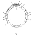
- the sealing device comprises an elastomeric plate 14 which is incompressible and deformable and has good creep resistance such as rubber or neoprene. This layer of a thickness between 0.3 and 3 cm, is intended to seal the leak by penetrating pressure in the upper part of the hole or crack.
- a force distributor 16 described below is placed above the elastomer plate 14.
- the distributor 16 has dimensions approximately equal to those of the elastomer plate 14 and is intended to apply and distribute the shear forces to the elastomer plate 14.
- a pressure distributor 18 for distributing the pressure due to clamping forces from the tightening of a strap composed of two flanges 20 and 22.
- the advantage of the strap is to avoid inducing excessive stresses in the wall of the pipe
- Each clamping flange extends between two end rods 24 and 26 for the flange 20, and the end rods 28 and 30 for the flange 22.
- the rods end 24 and 28 are connected by a threaded rod 32 and the rods 26 and 30 are connected by a threaded rod 34.
- the figure 2 represents the device according to the invention applied to a pipe for the purpose of sealing a leak due to a hole or a crack 12 located near a weld 13.
- the force distributor 16 fits perfectly to variations in height of the pipe due to the weld 13 and the following hollow due to the hole or crack.
- a pressure distributor 18 is placed above the force distributor 16 in order to distribute the clamping forces from the tightening of the strap composed of the two strands 20 and 22.
- the force distributor is composed of a support grid 40 having the shape of a rectangular plate whose size is adapted to the size of the hole or crack.
- the grid partitions have a depth of 2mm and a thickness of less than 1mm.
- the material used is preferably a rigid but deformable plastic material such as polyamide, polypropylene or polycarbonate, or is made of metal having the same deformability characteristic, in particular aluminum. The deformability of the grid 40 thus makes it possible to use the same force distributor regardless of the diameter of the pipe to be sealed.
- each force module 42, 44 or 46 illustrated on the figure 4 In each of the meshes 41 of the grid 40 is introduced a force module 42, 44 or 46 illustrated on the figure 4 .
- Each force module has a rectangular section of dimensions slightly smaller than those of the mesh so that the module can be introduced into the mesh.
- the module In order to be retained by the gate when the module is introduced into the mesh, the module preferably comprises a flange 48. The height of each module is between 5 mm and 40 mm.
- the force modules are slidably introduced into the grid and protrude above the grid of a height which depends on the variations of height of the pipe at the place of the crack. So, on the figure 1 the force modules are introduced deeper into the grid at the center of the hole or crack because it is a concave part. On the other hand, on the figure 2 the modules are introduced less deeply into the grid at the location of the weld 13 which is a convex part of the pipe.
- the force distributor 16 formed of the grid 40 and modules 42, 44 or 46 adapts perfectly to all forms of the pipe at the location of the leak.
- the grid could have any shape other than a triangular shape and the meshes of the grid are not necessarily rectangular.
- Each force module 42, 44 or 46 has at its lower end a rib on at least one side of the module and preferably on all sides so as to form a rectangle, in order to exert shear forces perpendicular to the elastomer plate 14.
- the modules may have a different height increasing as one goes from the edge of the grid to its center so that the force distributor 16 has a generally convex shape adapted to the strap of Tightening.
- the upper end of each module is preferably inclined as illustrated for the module 46 shown in FIG. figure 4 , this inclination being increasingly weak when going from the edges of the gille to the center of the grid.
- the pressure distributor 18 placed above the force distributor 16 is to uniformly distribute the pressures exerted by the clamping strap on the force distributor 16 and in particular on the ends of the force modules which, as has been seen above, are not at the same height because the surface of the pipe has height variations due to the concave or convex shape at the location of the leak.
- the pressure distributor 18 is a bag containing balls of plastic or metal having a size (or a diameter if they are spherical) less than 5 mm, so that the bag of balls can adapt to the slightest protuberance of the force distributor and fill spaces and interstices between the ends of the modules pressure.
- any clamping mechanism can be used to implement the invention.
- the use of two flanges (illustrated on figures 1 and 2 ) and in general of several flanges interconnected by appropriate clamping means bringing the ends of the flanges together when tightening (these clamping means may in particular be threaded rods as described in the preferred embodiment), is a system that adapts to all pipe diameters, each pipe may require the use of several identical flanges interconnected.
- the flanges that make up the strap are in a sheath so that part of the clamping force is not absorbed by the friction forces as is the case when the flanges rub directly on the pipe during tightening.
Landscapes
- Engineering & Computer Science (AREA)
- General Engineering & Computer Science (AREA)
- Mechanical Engineering (AREA)
- Pipe Accessories (AREA)
Claims (6)
- Vorrichtung zur Leckabdichtung in einer mindestens ein Loch oder einen Riss (12) aufweisenden Rohrleitung (10), die eine Elastomerplatte (14), die von einem aus einem Traggitter (40) bestehenden Kraftverteiler (16) gegen die Leckstelle angelegt wird, und einen Spanngurt (20, 22) enthält, der um die Rohrleitung herum angeordnet wird, um eine Kraft auf den Kraftverteiler auszuüben, wobei ein oberhalb des Kraftverteilers (16) angeordneter Druckverteiler (18) zum Zweck hat, die vom Spanngurt (20, 22) auf den Kraftverteiler ausgeübten Drücke gleichmäßig zu verteilen;
wobei die Vorrichtung dadurch gekennzeichnet ist, dass der Kraftverteiler aus unabhängigen Kraftmodulen (42, 44 oder 46) besteht, wobei jedes der Module in einer der Maschen des Gitters gleitend platziert und lotrecht zur Rohrleitung angeordnet ist, um Scherkräfte auf die Elastomerplatte an der Leckstelle auszuüben, die das Elastomermaterial dazu zwingen, sich so zu verformen, dass es die konkave oder konvexe Form der Rohrleitung an der Leckstelle annimmt und so das Loch oder den Riss verstopft. - Vorrichtung nach Anspruch 1, wobei der Druckverteiler (18) eine Tasche ist, die Kugeln einer Größe von weniger als 5 mm enthält.
- Vorrichtung nach Anspruch 1 oder 2, wobei das Traggitter eine rechtwinklige Form hat und Maschen rechtwinkliger Form aufweist.
- Vorrichtung nach Anspruch 3, wobei jedes der Kraftmodule (42, 44 oder 46) an seinem unteren Ende eine Rippe auf mindestens einer Seite des Moduls aufweist, mit dem Zweck, Scherkräfte lotrecht zur Elastomerplatte (14) auszuüben.
- Vorrichtung nach Anspruch 3 oder 4, wobei jedes der Kraftmodule (42, 44 oder 46) mindestens eine Randleiste (48) aufweist, um vom Gitter gehalten zu werden, wenn das Modul in die Masche eingeführt wird.
- Vorrichtung nach Anspruch 3 oder 4, wobei die Kraftmodule (46) unterschiedliche Höhen haben, wobei diese Höhe nach und nach vom Rand des Gitters zu seiner Mitte zunimmt, damit der Kraftverteiler (16) global eine konvexe Form hat, die an den Spanngurt (20, 22) angepasst ist.
Applications Claiming Priority (2)
| Application Number | Priority Date | Filing Date | Title |
|---|---|---|---|
| FR1004758A FR2968381B1 (fr) | 2010-12-07 | 2010-12-07 | Dispositif de colmatage de fuite dans une canalisation de transport de fluide. |
| PCT/FR2011/052877 WO2012076803A1 (fr) | 2010-12-07 | 2011-12-06 | Dispositif de colmatage de fuite dans une canalisation de transport de fluide. |
Publications (2)
| Publication Number | Publication Date |
|---|---|
| EP2649362A1 EP2649362A1 (de) | 2013-10-16 |
| EP2649362B1 true EP2649362B1 (de) | 2014-09-24 |
Family
ID=44462077
Family Applications (1)
| Application Number | Title | Priority Date | Filing Date |
|---|---|---|---|
| EP11804729.9A Active EP2649362B1 (de) | 2010-12-07 | 2011-12-06 | Vorrichtung zum abdichten eines lecks in einem flüssigkeitstransportrohr |
Country Status (9)
| Country | Link |
|---|---|
| US (1) | US8978709B2 (de) |
| EP (1) | EP2649362B1 (de) |
| CN (1) | CN103403433B (de) |
| BR (1) | BR112013013428B1 (de) |
| CA (1) | CA2819607C (de) |
| FR (1) | FR2968381B1 (de) |
| MX (1) | MX2013006494A (de) |
| RU (1) | RU2600207C2 (de) |
| WO (1) | WO2012076803A1 (de) |
Families Citing this family (8)
| Publication number | Priority date | Publication date | Assignee | Title |
|---|---|---|---|---|
| MC200157B1 (fr) | 2013-07-30 | 2014-02-19 | 3X Eng | Plaque de retenue pour bande de renforcement |
| MC200156B1 (fr) | 2013-07-30 | 2014-02-19 | 3X Eng | Bande de renforcement améliorée pour la réparation des canalisations de transport de fluides |
| CA2855396C (en) | 2014-06-26 | 2016-08-02 | Le Groupe Dsd Inc. | Tubing connector system |
| CN106015826A (zh) * | 2016-06-26 | 2016-10-12 | 杨越 | 无人船载管线维修套筒组件 |
| FR3071584B1 (fr) | 2017-09-24 | 2020-01-10 | 3X Engineering | Dispositif pour faciliter la reparation des pipelines |
| EP4010618A1 (de) * | 2019-08-10 | 2022-06-15 | Jndm Holdings Llc | Abdeckvorrichtung |
| FR3127272B1 (fr) * | 2021-09-22 | 2024-03-08 | 3X Eng | Dispositif de colmatage d'une fuite sur une canalisation de transport et/ou sur un réservoir de fluide |
| IT202200018195A1 (it) | 2022-09-06 | 2024-03-06 | Saipem Spa | Sistema e metodo di riparazione per riparare difetti localizzati di una tubazione per il trasporto di fluidi |
Family Cites Families (15)
| Publication number | Priority date | Publication date | Assignee | Title |
|---|---|---|---|---|
| DE78286C (de) * | E. wolf, Kitzingen | Rohrschelle für verschiedene Rohrdurchmesser mit federnder Anpressung der Dichtung | ||
| US785737A (en) * | 1904-09-03 | 1905-03-28 | Lloyd Jones | Device for stopping leaks. |
| US2069722A (en) * | 1936-02-27 | 1937-02-02 | M B Skinner Company | Pipe leak sealing gasket |
| US2529411A (en) * | 1945-12-07 | 1950-11-07 | Leonard C Hill | Gasket for repairing weld and pit leaks on pipes |
| US4606377A (en) * | 1984-10-30 | 1986-08-19 | Muenster Clamp, Inc. | Pipe repair clamp |
| US5247967A (en) * | 1991-08-29 | 1993-09-28 | Bourque Robert B | Pipe repair apparatus |
| DE69327847T2 (de) * | 1992-09-09 | 2000-06-15 | Clock Spring Co. L.P., Long Beach | Verfahren zur reparatur von rohren |
| US5497808A (en) * | 1994-10-31 | 1996-03-12 | Schlund; Jim D. | Fluid pressure line patch |
| FR2740199B1 (fr) | 1995-10-18 | 1998-01-02 | 3X Engineering | Manchon modulaire pour la protection, la reparation ou la renovation d'une canalisation |
| US5706862A (en) * | 1996-10-31 | 1998-01-13 | Meinerding, Sr.; Wesley C. | Pipe repair device |
| FR2782367B1 (fr) * | 1998-08-12 | 2000-09-22 | 3X Engineering | Dispositif de colmatage d'une fuite dans une canalisation |
| CN1243923C (zh) * | 2002-08-26 | 2006-03-01 | 上海科鸣建筑工程技术有限公司 | 地下钢筋混凝土管道接头防水堵漏修复方法 |
| FR2851635B1 (fr) | 2003-02-24 | 2006-06-30 | 3X Engineering | Manchon a insert pour la reparation d'une canalisation de transport de fluide a haute pression |
| RU2240468C1 (ru) * | 2003-04-17 | 2004-11-20 | Общество с ограниченной ответственностью "Севергазпром" | Муфта для ремонта трубопровода и способ ее установки |
| GB0714294D0 (en) * | 2007-07-21 | 2007-08-29 | Stats Uk Ltd | Sealing apparatus |
-
2010
- 2010-12-07 FR FR1004758A patent/FR2968381B1/fr active Active
-
2011
- 2011-12-06 EP EP11804729.9A patent/EP2649362B1/de active Active
- 2011-12-06 WO PCT/FR2011/052877 patent/WO2012076803A1/fr not_active Ceased
- 2011-12-06 BR BR112013013428-3A patent/BR112013013428B1/pt active IP Right Grant
- 2011-12-06 CN CN201180058894.4A patent/CN103403433B/zh active Active
- 2011-12-06 MX MX2013006494A patent/MX2013006494A/es active IP Right Grant
- 2011-12-06 CA CA2819607A patent/CA2819607C/fr active Active
- 2011-12-06 US US13/992,176 patent/US8978709B2/en active Active
- 2011-12-06 RU RU2013131104/06A patent/RU2600207C2/ru active
Also Published As
| Publication number | Publication date |
|---|---|
| BR112013013428B1 (pt) | 2020-10-06 |
| CN103403433B (zh) | 2015-05-20 |
| CN103403433A (zh) | 2013-11-20 |
| EP2649362A1 (de) | 2013-10-16 |
| RU2013131104A (ru) | 2015-01-20 |
| US8978709B2 (en) | 2015-03-17 |
| BR112013013428A2 (pt) | 2016-10-11 |
| CA2819607C (fr) | 2019-02-26 |
| FR2968381B1 (fr) | 2012-12-28 |
| MX2013006494A (es) | 2013-10-01 |
| RU2600207C2 (ru) | 2016-10-20 |
| FR2968381A1 (fr) | 2012-06-08 |
| WO2012076803A1 (fr) | 2012-06-14 |
| US20130264815A1 (en) | 2013-10-10 |
| CA2819607A1 (fr) | 2012-06-14 |
Similar Documents
| Publication | Publication Date | Title |
|---|---|---|
| EP2649362B1 (de) | Vorrichtung zum abdichten eines lecks in einem flüssigkeitstransportrohr | |
| EP1104532B1 (de) | Vorrichtung zur abdichtung eine leckage in einer rohrleitung | |
| CA2564109C (fr) | Methode de reparation d'une fuite sur une canalisation de gaz a l'endroit d'une bride | |
| CA2760074A1 (fr) | Dispositif de protection d'au moins une conduite disposee au fond d'une etendue d'eau et ensemble de transport de fluide associe | |
| EP1938011B1 (de) | Vorrichtung zur halterung sehr langer röhren oder pipelines in einer bestimmten position und zu ihrer dämpfung bezüglich fester trägerstrukturen | |
| EP0420732B1 (de) | Tropfenbewässerungsvorrichtung mit Abzweigverbindungen | |
| FR3127272A1 (fr) | Dispositif de colmatage d'une fuite sur une canalisation de transport et/ou sur un réservoir de fluide | |
| EP3027952B1 (de) | Halteplatte für einen verstärkungsstreifen | |
| EP1216378B1 (de) | Verbindungsanordnung von zwei rohrenden | |
| FR2506425A1 (fr) | Bouchon d'obturation dilatable des canalisations | |
| EP3201508B1 (de) | Vorrichtung und verfahren zur befestigung eines rohrelements an ein rohrende | |
| LU93135B1 (fr) | Système de calorifugeage | |
| FR2672372A1 (fr) | Dispositif de jonction etanche entre deux tuyaux cylindriques. | |
| FR2630525A1 (fr) | Dispositif de raccordement pour tuyauteries en matiere plastique | |
| FR2613258A1 (fr) | Appareil de mise en oeuvre d'un complexe organo-hydraulique d'etanchement de conduites enterrees | |
| FR2659720A1 (fr) | Perfectionnement aux appareillages d'etanchement de canalisations enterrees. | |
| FR2874020A1 (fr) | Procede de reparation in situ d'une zone pouvant comprendre une fissure a la surface d'une enceinte | |
| BE418463A (de) | ||
| FR2632546A1 (fr) | Dispositif de mise en oeuvre d'un complexe organo-hydraulique d'etanchement de conduites | |
| BE407975A (de) |
Legal Events
| Date | Code | Title | Description |
|---|---|---|---|
| PUAI | Public reference made under article 153(3) epc to a published international application that has entered the european phase |
Free format text: ORIGINAL CODE: 0009012 |
|
| 17P | Request for examination filed |
Effective date: 20130626 |
|
| AK | Designated contracting states |
Kind code of ref document: A1 Designated state(s): AL AT BE BG CH CY CZ DE DK EE ES FI FR GB GR HR HU IE IS IT LI LT LU LV MC MK MT NL NO PL PT RO RS SE SI SK SM TR |
|
| DAX | Request for extension of the european patent (deleted) | ||
| GRAP | Despatch of communication of intention to grant a patent |
Free format text: ORIGINAL CODE: EPIDOSNIGR1 |
|
| INTG | Intention to grant announced |
Effective date: 20140416 |
|
| GRAS | Grant fee paid |
Free format text: ORIGINAL CODE: EPIDOSNIGR3 |
|
| GRAA | (expected) grant |
Free format text: ORIGINAL CODE: 0009210 |
|
| AK | Designated contracting states |
Kind code of ref document: B1 Designated state(s): AL AT BE BG CH CY CZ DE DK EE ES FI FR GB GR HR HU IE IS IT LI LT LU LV MC MK MT NL NO PL PT RO RS SE SI SK SM TR |
|
| REG | Reference to a national code |
Ref country code: GB Ref legal event code: FG4D Free format text: NOT ENGLISH |
|
| REG | Reference to a national code |
Ref country code: CH Ref legal event code: EP |
|
| REG | Reference to a national code |
Ref country code: AT Ref legal event code: REF Ref document number: 688802 Country of ref document: AT Kind code of ref document: T Effective date: 20141015 |
|
| REG | Reference to a national code |
Ref country code: IE Ref legal event code: FG4D Free format text: LANGUAGE OF EP DOCUMENT: FRENCH |
|
| REG | Reference to a national code |
Ref country code: DE Ref legal event code: R096 Ref document number: 602011010176 Country of ref document: DE Effective date: 20141106 |
|
| PG25 | Lapsed in a contracting state [announced via postgrant information from national office to epo] |
Ref country code: LT Free format text: LAPSE BECAUSE OF FAILURE TO SUBMIT A TRANSLATION OF THE DESCRIPTION OR TO PAY THE FEE WITHIN THE PRESCRIBED TIME-LIMIT Effective date: 20140924 Ref country code: GR Free format text: LAPSE BECAUSE OF FAILURE TO SUBMIT A TRANSLATION OF THE DESCRIPTION OR TO PAY THE FEE WITHIN THE PRESCRIBED TIME-LIMIT Effective date: 20141225 Ref country code: FI Free format text: LAPSE BECAUSE OF FAILURE TO SUBMIT A TRANSLATION OF THE DESCRIPTION OR TO PAY THE FEE WITHIN THE PRESCRIBED TIME-LIMIT Effective date: 20140924 Ref country code: NO Free format text: LAPSE BECAUSE OF FAILURE TO SUBMIT A TRANSLATION OF THE DESCRIPTION OR TO PAY THE FEE WITHIN THE PRESCRIBED TIME-LIMIT Effective date: 20141224 Ref country code: SE Free format text: LAPSE BECAUSE OF FAILURE TO SUBMIT A TRANSLATION OF THE DESCRIPTION OR TO PAY THE FEE WITHIN THE PRESCRIBED TIME-LIMIT Effective date: 20140924 |
|
| REG | Reference to a national code |
Ref country code: LT Ref legal event code: MG4D Ref country code: NL Ref legal event code: VDEP Effective date: 20140924 |
|
| PG25 | Lapsed in a contracting state [announced via postgrant information from national office to epo] |
Ref country code: HR Free format text: LAPSE BECAUSE OF FAILURE TO SUBMIT A TRANSLATION OF THE DESCRIPTION OR TO PAY THE FEE WITHIN THE PRESCRIBED TIME-LIMIT Effective date: 20140924 Ref country code: LV Free format text: LAPSE BECAUSE OF FAILURE TO SUBMIT A TRANSLATION OF THE DESCRIPTION OR TO PAY THE FEE WITHIN THE PRESCRIBED TIME-LIMIT Effective date: 20140924 Ref country code: CY Free format text: LAPSE BECAUSE OF FAILURE TO SUBMIT A TRANSLATION OF THE DESCRIPTION OR TO PAY THE FEE WITHIN THE PRESCRIBED TIME-LIMIT Effective date: 20140924 Ref country code: RS Free format text: LAPSE BECAUSE OF FAILURE TO SUBMIT A TRANSLATION OF THE DESCRIPTION OR TO PAY THE FEE WITHIN THE PRESCRIBED TIME-LIMIT Effective date: 20140924 |
|
| REG | Reference to a national code |
Ref country code: AT Ref legal event code: MK05 Ref document number: 688802 Country of ref document: AT Kind code of ref document: T Effective date: 20140924 |
|
| PG25 | Lapsed in a contracting state [announced via postgrant information from national office to epo] |
Ref country code: NL Free format text: LAPSE BECAUSE OF FAILURE TO SUBMIT A TRANSLATION OF THE DESCRIPTION OR TO PAY THE FEE WITHIN THE PRESCRIBED TIME-LIMIT Effective date: 20140924 |
|
| PG25 | Lapsed in a contracting state [announced via postgrant information from national office to epo] |
Ref country code: RO Free format text: LAPSE BECAUSE OF FAILURE TO SUBMIT A TRANSLATION OF THE DESCRIPTION OR TO PAY THE FEE WITHIN THE PRESCRIBED TIME-LIMIT Effective date: 20140924 Ref country code: CZ Free format text: LAPSE BECAUSE OF FAILURE TO SUBMIT A TRANSLATION OF THE DESCRIPTION OR TO PAY THE FEE WITHIN THE PRESCRIBED TIME-LIMIT Effective date: 20140924 Ref country code: EE Free format text: LAPSE BECAUSE OF FAILURE TO SUBMIT A TRANSLATION OF THE DESCRIPTION OR TO PAY THE FEE WITHIN THE PRESCRIBED TIME-LIMIT Effective date: 20140924 Ref country code: SK Free format text: LAPSE BECAUSE OF FAILURE TO SUBMIT A TRANSLATION OF THE DESCRIPTION OR TO PAY THE FEE WITHIN THE PRESCRIBED TIME-LIMIT Effective date: 20140924 Ref country code: PT Free format text: LAPSE BECAUSE OF FAILURE TO SUBMIT A TRANSLATION OF THE DESCRIPTION OR TO PAY THE FEE WITHIN THE PRESCRIBED TIME-LIMIT Effective date: 20150126 Ref country code: ES Free format text: LAPSE BECAUSE OF FAILURE TO SUBMIT A TRANSLATION OF THE DESCRIPTION OR TO PAY THE FEE WITHIN THE PRESCRIBED TIME-LIMIT Effective date: 20140924 Ref country code: IS Free format text: LAPSE BECAUSE OF FAILURE TO SUBMIT A TRANSLATION OF THE DESCRIPTION OR TO PAY THE FEE WITHIN THE PRESCRIBED TIME-LIMIT Effective date: 20150124 |
|
| PG25 | Lapsed in a contracting state [announced via postgrant information from national office to epo] |
Ref country code: AT Free format text: LAPSE BECAUSE OF FAILURE TO SUBMIT A TRANSLATION OF THE DESCRIPTION OR TO PAY THE FEE WITHIN THE PRESCRIBED TIME-LIMIT Effective date: 20140924 Ref country code: PL Free format text: LAPSE BECAUSE OF FAILURE TO SUBMIT A TRANSLATION OF THE DESCRIPTION OR TO PAY THE FEE WITHIN THE PRESCRIBED TIME-LIMIT Effective date: 20140924 |
|
| REG | Reference to a national code |
Ref country code: DE Ref legal event code: R097 Ref document number: 602011010176 Country of ref document: DE |
|
| PG25 | Lapsed in a contracting state [announced via postgrant information from national office to epo] |
Ref country code: BE Free format text: LAPSE BECAUSE OF NON-PAYMENT OF DUE FEES Effective date: 20141231 |
|
| PG25 | Lapsed in a contracting state [announced via postgrant information from national office to epo] |
Ref country code: LU Free format text: LAPSE BECAUSE OF FAILURE TO SUBMIT A TRANSLATION OF THE DESCRIPTION OR TO PAY THE FEE WITHIN THE PRESCRIBED TIME-LIMIT Effective date: 20141206 Ref country code: DK Free format text: LAPSE BECAUSE OF FAILURE TO SUBMIT A TRANSLATION OF THE DESCRIPTION OR TO PAY THE FEE WITHIN THE PRESCRIBED TIME-LIMIT Effective date: 20140924 |
|
| PLBE | No opposition filed within time limit |
Free format text: ORIGINAL CODE: 0009261 |
|
| REG | Reference to a national code |
Ref country code: CH Ref legal event code: PL |
|
| STAA | Information on the status of an ep patent application or granted ep patent |
Free format text: STATUS: NO OPPOSITION FILED WITHIN TIME LIMIT |
|
| PG25 | Lapsed in a contracting state [announced via postgrant information from national office to epo] |
Ref country code: IT Free format text: LAPSE BECAUSE OF FAILURE TO SUBMIT A TRANSLATION OF THE DESCRIPTION OR TO PAY THE FEE WITHIN THE PRESCRIBED TIME-LIMIT Effective date: 20140924 |
|
| 26N | No opposition filed |
Effective date: 20150625 |
|
| REG | Reference to a national code |
Ref country code: IE Ref legal event code: MM4A |
|
| PG25 | Lapsed in a contracting state [announced via postgrant information from national office to epo] |
Ref country code: LI Free format text: LAPSE BECAUSE OF NON-PAYMENT OF DUE FEES Effective date: 20141231 Ref country code: CH Free format text: LAPSE BECAUSE OF NON-PAYMENT OF DUE FEES Effective date: 20141231 Ref country code: IE Free format text: LAPSE BECAUSE OF NON-PAYMENT OF DUE FEES Effective date: 20141206 |
|
| REG | Reference to a national code |
Ref country code: FR Ref legal event code: PLFP Year of fee payment: 5 |
|
| PG25 | Lapsed in a contracting state [announced via postgrant information from national office to epo] |
Ref country code: SI Free format text: LAPSE BECAUSE OF FAILURE TO SUBMIT A TRANSLATION OF THE DESCRIPTION OR TO PAY THE FEE WITHIN THE PRESCRIBED TIME-LIMIT Effective date: 20140924 |
|
| PG25 | Lapsed in a contracting state [announced via postgrant information from national office to epo] |
Ref country code: SM Free format text: LAPSE BECAUSE OF FAILURE TO SUBMIT A TRANSLATION OF THE DESCRIPTION OR TO PAY THE FEE WITHIN THE PRESCRIBED TIME-LIMIT Effective date: 20140924 |
|
| PG25 | Lapsed in a contracting state [announced via postgrant information from national office to epo] |
Ref country code: MC Free format text: LAPSE BECAUSE OF FAILURE TO SUBMIT A TRANSLATION OF THE DESCRIPTION OR TO PAY THE FEE WITHIN THE PRESCRIBED TIME-LIMIT Effective date: 20140924 |
|
| PG25 | Lapsed in a contracting state [announced via postgrant information from national office to epo] |
Ref country code: BG Free format text: LAPSE BECAUSE OF FAILURE TO SUBMIT A TRANSLATION OF THE DESCRIPTION OR TO PAY THE FEE WITHIN THE PRESCRIBED TIME-LIMIT Effective date: 20140924 |
|
| PG25 | Lapsed in a contracting state [announced via postgrant information from national office to epo] |
Ref country code: TR Free format text: LAPSE BECAUSE OF FAILURE TO SUBMIT A TRANSLATION OF THE DESCRIPTION OR TO PAY THE FEE WITHIN THE PRESCRIBED TIME-LIMIT Effective date: 20140924 Ref country code: MT Free format text: LAPSE BECAUSE OF FAILURE TO SUBMIT A TRANSLATION OF THE DESCRIPTION OR TO PAY THE FEE WITHIN THE PRESCRIBED TIME-LIMIT Effective date: 20140924 Ref country code: HU Free format text: LAPSE BECAUSE OF FAILURE TO SUBMIT A TRANSLATION OF THE DESCRIPTION OR TO PAY THE FEE WITHIN THE PRESCRIBED TIME-LIMIT; INVALID AB INITIO Effective date: 20111206 |
|
| REG | Reference to a national code |
Ref country code: FR Ref legal event code: PLFP Year of fee payment: 6 |
|
| REG | Reference to a national code |
Ref country code: FR Ref legal event code: PLFP Year of fee payment: 7 |
|
| PG25 | Lapsed in a contracting state [announced via postgrant information from national office to epo] |
Ref country code: MK Free format text: LAPSE BECAUSE OF FAILURE TO SUBMIT A TRANSLATION OF THE DESCRIPTION OR TO PAY THE FEE WITHIN THE PRESCRIBED TIME-LIMIT Effective date: 20140924 |
|
| PG25 | Lapsed in a contracting state [announced via postgrant information from national office to epo] |
Ref country code: AL Free format text: LAPSE BECAUSE OF FAILURE TO SUBMIT A TRANSLATION OF THE DESCRIPTION OR TO PAY THE FEE WITHIN THE PRESCRIBED TIME-LIMIT Effective date: 20140924 |
|
| P01 | Opt-out of the competence of the unified patent court (upc) registered |
Effective date: 20230512 |
|
| PGFP | Annual fee paid to national office [announced via postgrant information from national office to epo] |
Ref country code: GB Payment date: 20251229 Year of fee payment: 15 |
|
| PGFP | Annual fee paid to national office [announced via postgrant information from national office to epo] |
Ref country code: FR Payment date: 20251230 Year of fee payment: 15 |
|
| PGFP | Annual fee paid to national office [announced via postgrant information from national office to epo] |
Ref country code: DE Payment date: 20251231 Year of fee payment: 15 |