EP2649507B1 - Dispositif micro-fluidique pour l'analyse d'un échantillon de fluide - Google Patents
Dispositif micro-fluidique pour l'analyse d'un échantillon de fluide Download PDFInfo
- Publication number
- EP2649507B1 EP2649507B1 EP11794476.9A EP11794476A EP2649507B1 EP 2649507 B1 EP2649507 B1 EP 2649507B1 EP 11794476 A EP11794476 A EP 11794476A EP 2649507 B1 EP2649507 B1 EP 2649507B1
- Authority
- EP
- European Patent Office
- Prior art keywords
- touch screen
- micro
- capacitive touch
- microfluidic device
- electrode
- Prior art date
- Legal status (The legal status is an assumption and is not a legal conclusion. Google has not performed a legal analysis and makes no representation as to the accuracy of the status listed.)
- Active
Links
Images



Classifications
-
- G—PHYSICS
- G01—MEASURING; TESTING
- G01N—INVESTIGATING OR ANALYSING MATERIALS BY DETERMINING THEIR CHEMICAL OR PHYSICAL PROPERTIES
- G01N33/00—Investigating or analysing materials by specific methods not covered by groups G01N1/00 - G01N31/00
- G01N33/48—Biological material, e.g. blood, urine; Haemocytometers
- G01N33/483—Physical analysis of biological material
- G01N33/487—Physical analysis of biological material of liquid biological material
- G01N33/48785—Electrical and electronic details of measuring devices for physical analysis of liquid biological material not specific to a particular test method, e.g. user interface or power supply
-
- B—PERFORMING OPERATIONS; TRANSPORTING
- B01—PHYSICAL OR CHEMICAL PROCESSES OR APPARATUS IN GENERAL
- B01L—CHEMICAL OR PHYSICAL LABORATORY APPARATUS FOR GENERAL USE
- B01L3/00—Containers or dishes for laboratory use, e.g. laboratory glassware; Droppers
- B01L3/50—Containers for the purpose of retaining a material to be analysed, e.g. test tubes
- B01L3/502—Containers for the purpose of retaining a material to be analysed, e.g. test tubes with fluid transport, e.g. in multi-compartment structures
- B01L3/5027—Containers for the purpose of retaining a material to be analysed, e.g. test tubes with fluid transport, e.g. in multi-compartment structures by integrated microfluidic structures, i.e. dimensions of channels and chambers are such that surface tension forces are important, e.g. lab-on-a-chip
- B01L3/502715—Containers for the purpose of retaining a material to be analysed, e.g. test tubes with fluid transport, e.g. in multi-compartment structures by integrated microfluidic structures, i.e. dimensions of channels and chambers are such that surface tension forces are important, e.g. lab-on-a-chip characterised by interfacing components, e.g. fluidic, electrical, optical or mechanical interfaces
-
- G—PHYSICS
- G06—COMPUTING OR CALCULATING; COUNTING
- G06F—ELECTRIC DIGITAL DATA PROCESSING
- G06F3/00—Input arrangements for transferring data to be processed into a form capable of being handled by the computer; Output arrangements for transferring data from processing unit to output unit, e.g. interface arrangements
- G06F3/01—Input arrangements or combined input and output arrangements for interaction between user and computer
- G06F3/03—Arrangements for converting the position or the displacement of a member into a coded form
- G06F3/041—Digitisers, e.g. for touch screens or touch pads, characterised by the transducing means
- G06F3/044—Digitisers, e.g. for touch screens or touch pads, characterised by the transducing means by capacitive means
-
- B—PERFORMING OPERATIONS; TRANSPORTING
- B01—PHYSICAL OR CHEMICAL PROCESSES OR APPARATUS IN GENERAL
- B01L—CHEMICAL OR PHYSICAL LABORATORY APPARATUS FOR GENERAL USE
- B01L2300/00—Additional constructional details
- B01L2300/02—Identification, exchange or storage of information
- B01L2300/021—Identification, e.g. bar codes
- B01L2300/022—Transponder chips
-
- B—PERFORMING OPERATIONS; TRANSPORTING
- B01—PHYSICAL OR CHEMICAL PROCESSES OR APPARATUS IN GENERAL
- B01L—CHEMICAL OR PHYSICAL LABORATORY APPARATUS FOR GENERAL USE
- B01L2300/00—Additional constructional details
- B01L2300/06—Auxiliary integrated devices, integrated components
- B01L2300/0627—Sensor or part of a sensor is integrated
- B01L2300/0645—Electrodes
-
- Y—GENERAL TAGGING OF NEW TECHNOLOGICAL DEVELOPMENTS; GENERAL TAGGING OF CROSS-SECTIONAL TECHNOLOGIES SPANNING OVER SEVERAL SECTIONS OF THE IPC; TECHNICAL SUBJECTS COVERED BY FORMER USPC CROSS-REFERENCE ART COLLECTIONS [XRACs] AND DIGESTS
- Y10—TECHNICAL SUBJECTS COVERED BY FORMER USPC
- Y10T—TECHNICAL SUBJECTS COVERED BY FORMER US CLASSIFICATION
- Y10T436/00—Chemistry: analytical and immunological testing
- Y10T436/14—Heterocyclic carbon compound [i.e., O, S, N, Se, Te, as only ring hetero atom]
- Y10T436/142222—Hetero-O [e.g., ascorbic acid, etc.]
- Y10T436/143333—Saccharide [e.g., DNA, etc.]
- Y10T436/144444—Glucose
-
- Y—GENERAL TAGGING OF NEW TECHNOLOGICAL DEVELOPMENTS; GENERAL TAGGING OF CROSS-SECTIONAL TECHNOLOGIES SPANNING OVER SEVERAL SECTIONS OF THE IPC; TECHNICAL SUBJECTS COVERED BY FORMER USPC CROSS-REFERENCE ART COLLECTIONS [XRACs] AND DIGESTS
- Y10—TECHNICAL SUBJECTS COVERED BY FORMER USPC
- Y10T—TECHNICAL SUBJECTS COVERED BY FORMER US CLASSIFICATION
- Y10T436/00—Chemistry: analytical and immunological testing
- Y10T436/20—Oxygen containing
- Y10T436/203332—Hydroxyl containing
- Y10T436/204165—Ethanol
Definitions
- the present invention relates to a microfluidic device for the analysis of a fluid sample, and a fluid sample analysis system comprising such a device.
- the present invention also relates to a programmable device with a capacitive touch screen containing a processor executing software for analyzing this sample and displaying the results of this analysis.
- Micro-fluidic chips are widely used in the field of diagnostics for the detection of various pathologies. They make it possible to perform one or more analyzes quickly and accurately on a single chip using a very small sample volume to be analyzed. These chips, also known as “biochip” or “lab-on-a-chip” are generally single-use and require an interface with a computer or other devices to display the results of the test. 'analysis.
- the detection signal is then converted into an electrical signal to undergo processing (filtering, sampling, etc.) and to allow analysis of the characteristics of the fluid sample, for example its composition, temperature, fluid velocity, viscosity, conductivity , pH, etc.
- each micro-fluidic chip and its interface are generally developed for a specific application, which reduces the modularity and flexibility of the chip.
- microfluidic support including elements such as valves, pumps, etc. to exert pressure on the micro-channels are activated by an external element such as an interactive touch screen by which the pressure on the channels can be exerted.
- an external element such as an interactive touch screen by which the pressure on the channels can be exerted.
- the support works with a device for Braille writing, which can be controlled by computer through a simple text editor.
- the touch device is only used for the entry of commands.
- WO2008117223 discloses a biochip incorporating actuators and / or sensors arranged in matrix ways to interact with the microfluidic device. Each actuator / sensor can be individually activated using an active matrix of thin-film technology transistors. However, interpretation and analysis of results are performed on an external device. In addition, the electronics must be directly integrated on the chip thus increasing biochip manufacturing costs.
- US2010279418 relates to a glucose measuring device having a door for receiving a test strip and a connection for connecting to a portable device such as an IPhone.
- the device glucose measurement may include a display to display the results of the measurement.
- WO2005001680 relates to a user interface for a portable medical diagnostic device and the method of use thereof.
- the medical diagnostic apparatus includes a touch screen for displaying a graphical user interface (GUI) including virtual selectors.
- GUI graphical user interface
- a port is for receiving a sample placed on a test strip.
- a detector connected with a microprocessor integrated into the device, allows the analysis of the sample.
- US20100249965 relates to a device for measuring glucose to receive a strip and to be connected to the audio ports of a portable device.
- WO03004160 apparatus and method for carrying out an electrochemical metering or reaction involving conductivity and / or electric current so as to achieve reduction, oxidation or ion transfer reaction, conductimetry and / or impedance, or to create an electric field in a solution, or to perform a combination thereof.
- the device comprises at least one microchip having a micro-channel or a micro-channel network provided with a tip end for taking a fluid sample and / or depositing a fluid sample, a micro connection end -fluidic and an integrated electrode in the micro-channel.
- An object of the present invention is to provide a device for the analysis of a fluid sample which is free from the limitations of known microfluidic chips.
- Another object of the invention is to propose a device for the analysis of a fluid sample that is more modular, flexible and less expensive than the known solutions.
- This invention exploits the capacitive sensing methods of a programmable device with a capacitive touch screen as an interface between the fluid sample and an analysis tool.
- the idea proposed here is to use a programmable device with a capacitive touch screen, for example a touch pad, as an interface and also as a calculation unit for analyzing a microfluidic device, for example a microfluidic chip. .
- the capacitive touch screen of the programmable device can be likened to a device operating as an input / output that could be exploited as a detection interface.
- programmable devices with capacitive touch screens are today produced in industrial quantities and affordable for a consumer market.
- these devices benefit from computing power increased with powerful microprocessors and, thanks to the progress of the microelectronics industry, have a low consumption.
- the programmable device with a capacitive touch screen can be configured to allow the analysis of a microfluidic device of different types or of several microfluidic devices, of the same type or of different types.
- several programmable devices with capacitive touch screen can be used in parallel and communicate the results of the analyzes to each other.
- the present invention combines the three functions ( detection, analysis and display) in one thanks to the use of a programmable device with a capacitive touch screen.
- the present invention relates to a microfluidic device 1 for the analysis of a fluid sample using as interface, means for analyzing the sample and displaying the results of the analysis a programmable device with a capacitive touch screen 2, that is to say based on a so-called capacitive technology.
- the fluid of the sample may be a liquid, for example, but without limitation, blood, urine, serum, blood plasma, saliva, secretions, or a gas, for example, but in a non-limiting manner of the breath.
- Programmable devices with a current touch screen are based primarily on two technologies: one resistive the other capacitive.
- Resistive technology consists of superimposing two transparent conductive films separated by a slight gap. When an action on the device, the pressure exerted by the touch creates a mechanical deformation of the upper film and will come into contact with the lower film thereby creating an electrical contact between these two films. Resistance measurement is used to detect and locate the contact.
- the advantage of this technology is the possibility of using both objects and fingers as long as the pressure is sufficient to deform the top film. On the other hand, these types of devices will tend to wear and scratch more easily due to the low mechanical strength of the top film.
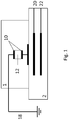
- Capacitive technology consists of embedding two transparent electrode arrays composed of ITO (Indium Tin Oxide), the first network composed of detection electrodes 20 and the second by excitation electrodes 22, visible in section on the figure 1 , the two networks being arranged perpendicularly relative to each other in the touch device.
- ITO Indium Tin Oxide
- the two networks being arranged perpendicularly relative to each other in the touch device.
- a device with a touch screen with capacitive technology 2 can exploit the impedance variation Z sample , visible on the figure 2 caused by a micro-fluidic device 1.
- the impedance variation for example a capacitance variation, will not be generated by a touch of the finger, but by the variation of the composition or characteristics of a sample placed on a surface 121 between two electrodes 10 of the microfluidic device 1 ( figures 1 and 4 ).
- the programmable device with capacitive touch screen 2 comprises a processor executing software to perform a detection of the microfluidic device 1.
- the detection makes it possible, by means of software stored in the programmable device 2, to interpret the quantity of charges in deficit and thus to analyze the fluid sample. The amount of lost charges will be analyzed according to the position on the capacitive touch device 2 and the time.
- the programmable device with capacitive touch screen 2 is also "multitouch", it allows to manage independently several reading areas simultaneously for multiple analyzes.
- a microfluidic device 1 is arranged to interfere directly on the display surface 24 of a programmable device with a capacitive touch screen 2, for example a touch pad or a multifunction telephone ("smartphone") which will detect the presence of the microfluidic device 1, analyze the information from the microfluidic device 1 according to the composition of the sample to be analyzed and display the results of this analysis on the capacitive touch screen.
- a capacitive touch screen for example a touch pad or a multifunction telephone (“smartphone") which will detect the presence of the microfluidic device 1, analyze the information from the microfluidic device 1 according to the composition of the sample to be analyzed and display the results of this analysis on the capacitive touch screen.
- the programmable device with capacitive touch screen 2 advantageously comprises a memory executing a software for analyzing the load variations caused by the microfluidic device 1 on the capacitive touch screen of the programmable device 2, and to deduce therefrom test analysis results. the fluid sample.
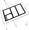
- the sample would first be injected into the microfluidic device 1, which is disposable, and then simply placed on a reading zone or surface 28 defined on the display surface 4 of the programmable device with capacitive touch screen 2, visible on the figure 3 .
- This surface 28 of the programmable device intended to interface with the microfluidic device comprises a surface 26 intended to interface with at least one electrode 10 of the microfluidic device 1.
- the surfaces 26 and 28 will be displayed on the programmable device 2 before the support of the microfluidic device 1.
- the programmable device with capacitive touch screen may comprise several surfaces 28.
- the programmable device with capacitive touch screen 2 After analyzing the information from the microfluidic device 1 as a function of the composition of the sample to be analyzed, the programmable device with capacitive touch screen 2 displays the results of the analysis.
- the microfluidic device 1 is composed of one or more electrodes 10 for interfacing with the programmable device with capacitive touch screen 2 and one or more inputs / outputs 14 or 16 respectively of at least one micro-channel 12 for the introduction of the sample to be diagnosed ( figure 4 ).
- the detection surface 13 is located in the part of the microchannel 10 which is superimposed on the comb electrode array 10.
- the analyte to be tested is placed on one or more surfaces 121 of the channels 12 facing the detection zone 13.
- the microfluidic device 1 is disposable and disposable. In a variant it is made of polymer using micro-manufacturing methods, for example thermoforming methods, mastered and well suited for low-cost industrial production.
- the microfluidic device 1 may be associated with an external electronic amplification of a signal or to actuate a plurality of its parts, for example micro-valves, pumps.
- the microfluidic device 1 is made of several parts, one of which may be disposable while the other may be single-use also, or preferably reusable.
- the microfluidic device 1 has a disposable portion with one or more surfaces 121 for the sample to be tested, as well as electrodes, and a reusable intermediate device to be placed on the touch screen.
- the disposable portion is plugged and / or electrically connected to the intermediate device, so that the electrodes of the disposable portion are in electrical connection with the electrodes of the intermediate device.
- the intermediate device is thus not in contact with the fluid to be tested, and can be reused. Electrodes the intermediate device is then in electrical contact with the electrical circuit of the disposable portion, the impedance of which depends on the fluid to be tested. This variable impedance is detected by the capacitive electrodes of the touch screen 2.
- the microfluidic device 1 ensures an electrical contact of the electrodes 10 with the mass 18 making it possible to close the circuit for circulating electric charges.
- the microfluidic device 1 cooperates with a programmable device with a modified capacitive touch screen 2.
- the surface of the tactile device comprises one or more slots 25, for example rectangular, round or in-line channel housings or in network for example. These housings are directly etched or produced in the outer surface 24 of the glass covering the touch screen, with a depth for example less than 2 millimeters.
- the housings 25 make it possible to house the analyte (droplet or a trickle of liquid or gas) to be tested placed directly on a surface 121 below the bottom surface of the microfluidic device 1, which is flat in this example.
- the liquid to be analyzed is placed directly on the modified capacitive screen 2, for example directly in the housing 25, or at the end of a channel which brings the fluid into these housing by capillarity.
- the liquid can also be introduced at the end of a channel into the microfluidic device, and flow by capillarity or gravity into the housing 25 etched in the screen of the device 25.
- the housings are constituted by holes or blind holes in a plate plated on the tactile surface of the tactile device 2, to create an extra thickness to create housing deep enough to accommodate drops of liquid to test over the touch device.
- This device is thus easier to use for certain applications; it suffices to deposit a drop of liquid at one or more predefined locations under the lower surface of the microfluidic device 1, then to apply this microfluidic device at the right place against the screen of the tactile device 2 so that the drops of liquid to be tested are located in the housing or housing 25 provided for this purpose during the test. It is also possible to provide channels through the microfluidic device 1 in order to bring the liquid (or the gas by an incoming flow) by capillarity introduced to another place in the predefined surfaces in front of the housing 25.
- microfluidic device of the figure 5 can also in a variant not shown have a lower surface that is not flat, for example with housing facing the housing 25, to receive larger volumes of analytes without having to burn too large housing in the device 2.
- the figure 2 illustrates an equivalent circuit diagram of the interface between the programmable device with capacitive touch screen 2 and the microfluidic device 1: the programmable device 2 is schematized with a U power voltage generator, a capacitor C 1 and a resistor R read . The coupling between the programmable device with capacitive touch screen 2 and the microfluidic device 1 is shown schematically with a capacitance C 2 .
- the microfluidic device 1 is schematized with an impedance Z sample , variable according to the sample to be analyzed, and connected to ground.
- Software stored in a memory of the programmable device with capacitive touch screen 2 makes it possible to directly read and analyze the data read on the microfluidic device 1 and then display the results on the capacitive touch screen of the device 2.
- the software is therefore capable of quantifying the variations of the impedance of the programmable device 2 created by the microfluidic device 1 and of determining one or more characteristics of the sample to be analyzed.
- the software can analyze several microfluidic devices 1 simultaneously as long as the surface of the capacitive touch screen of the programmable device 2 and the computing capacity of its processor allow it.
- the software makes it possible to control the touch screen controller, in order to avoid or modify the filtering usually performed by this controller to avoid impedance variations that are not produced by a user's finger.
- a new firmware is loaded into this controller.
- the software makes it possible to avoid or modify the software processing of the keys usually performed, in addition to the processing by the touch screen controller, by the operating system of the device 2.
- the controller controlling the capacitive touch screen can operate in hybrid mode: a "standard” mode and a “sample analysis (s)" mode.
- the controller operates as in a conventional touch device, for example a touch pad or a smartphone. He is able to distinguish between voluntary touches (one or more fingers) and involuntary touches (palms, ears, cheeks, etc.).
- the controller is able to detect the load variations of the screen interfaced with the microfluidic device in one or more specific areas of detection of the screen.
- an additional controller for the "sample analysis (s)" mode only may be implemented in a conventional controller operating in "standard” mode to process the signals. Switching from one mode to another can be done either automatically or manually via interface software executed by the device 2.
- the reading surfaces 26 of the electrodes and the microfluidic device 1, as well as their numbers, can be configured according to the microfluidic device 1 used.
- the software also offers the possibility of exporting the results data directly through the programmable device with capacitive touch screen 2.
- the programmable device 2 comprises means without and / or with wires for exporting the results of the analysis to an external computer, for example using a 3G / 4G interface, Wifi, Bluetooth, USB, etc.
- Data exported via the internet or other means of communication may be reinterpreted and stored by competent personnel.
- the data may be listed on a user's account to trace a history of the analyzes.
- the programmable device with capacitive touch screen 2 also comprises means for storing the results of the analysis.
- the results of the analysis will not be displayed on the capacitive touch screen of the programmable device 2, but will be sent to an external device on which they will be displayed.
- the disposable portion may be decoupled from the possible external electronic part in order to reduce the manufacturing costs of this first.
- the analysis is done on a programmable device with existing capacitive touch screen, for example a touch pad or smartphones, no dedicated analysis system should be developed accordingly.
- a programmable device with a capacitive touch screen 2 to interface with a microfluidic device 1 is a simple diagnostic method that can attract larger markets than more robust but also more expensive devices.
- the software for the acquisition, analysis and display of the results of the analysis may be marketed via online sales platforms.
- Several software can be marketed according to the needs of different users (individuals, medical staff, doctors, humanitarian organizations).
- the micro-fluidic device 1 in a variant comprises a combination of number and / or shape of electrodes which enables the programmable device with capacitive touch screen 1 to identify it and / or to identify the type (s) method of analysis and / or identification of the user of the microfluidic device 1.
- the electrodes have a bar-like mono or two-dimensional form.
- the microfluidic device 1 comprises an RFID tag which can be read by an RFID reader integrated in the programmable device 2.
- the microfluidic device 1 comprises a coating to promote interaction and analysis with the fluid sample.
- enzymes or molecules could be previously fixed on the electrode (s) 10 and / or the micro-channel (micro-channels) 12.
- the surface 121 for placing the analyte for example the electrode on which it is placed, or another portion of the microchannels 12, can undergo a chemical functionalization operation.
- the purpose of the chemical functionalization of the surface is to recognize only specific molecules (contained in the sample to be analyzed) that will adhere to the surface. The capacitance variation is then due to the recognition and then the adhesion of this specific molecule (and not the others in the sample).
- Different surfaces 121 in the same microfluidic device 1 may have different functionalizations to react each specifically to a specific type of molecule for different analyzes.
- the results of the analysis on the fluid sample can be combined with data of the programmable device 2, which could comprise for example a GPS module, to make statistical analyzes and / or to follow the geographical evolution of these results.
Landscapes
- Health & Medical Sciences (AREA)
- Engineering & Computer Science (AREA)
- Chemical & Material Sciences (AREA)
- Life Sciences & Earth Sciences (AREA)
- Physics & Mathematics (AREA)
- Biomedical Technology (AREA)
- General Health & Medical Sciences (AREA)
- Analytical Chemistry (AREA)
- Hematology (AREA)
- Biophysics (AREA)
- Human Computer Interaction (AREA)
- General Physics & Mathematics (AREA)
- Clinical Laboratory Science (AREA)
- Dispersion Chemistry (AREA)
- Chemical Kinetics & Catalysis (AREA)
- Medicinal Chemistry (AREA)
- Biochemistry (AREA)
- Immunology (AREA)
- Pathology (AREA)
- Food Science & Technology (AREA)
- Urology & Nephrology (AREA)
- Molecular Biology (AREA)
- General Engineering & Computer Science (AREA)
- Theoretical Computer Science (AREA)
- Investigating Or Analyzing Materials By The Use Of Electric Means (AREA)
- Automatic Analysis And Handling Materials Therefor (AREA)
Description
- La présente invention concerne un dispositif micro-fluidique pour l'analyse d'un échantillon de fluide, et un système d'analyse d'échantillon de fluide comportant un tel dispositif. La présente invention concerne aussi un dispositif programmable avec un écran tactile capacitif contenant un processeur exécutant un logiciel pour analyser cet échantillon et afficher les résultats de cette analyse.
- Les puces micro-fluidiques sont largement utilisées dans le domaine des diagnostics pour la détection de pathologies diverses. Elles permettent d'effectuer une ou plusieurs analyses de façon rapide et précise sur une seule même puce en utilisant un très faible volume d'échantillon à analyser. Ces puces, connues aussi sous le nom de « biochip » ou « lab-on-a-chip » sont en général à usage unique et nécessitent d'une interface avec un ordinateur ou d'autres dispositifs afin d'afficher les résultats de l'analyse.
- Afin de détecter l'échantillon, différentes méthodes sont utilisées, parmi lesquelles les méthodes de détection optiques, magnétiques, électromagnétiques, piézoélectriques, résistive et capacitives, ampérométrique et coulométrique.
- Le signal de détection est ensuite converti en signal électrique pour subir des traitements (filtrage, échantillonnage, etc.) et permettre l'analyse des caractéristiques de l'échantillon de fluide, par exemple sa composition, température, vitesse du fluide, viscosité, conductivité, pH, etc.
- Quelque soit la méthode de détection utilisée, chaque puce micro-fluidique et son interface sont généralement développées pour une application spécifique, ce qui diminue la modularité et la flexibilité de la puce.
- L'intégration de l'électronique d'analyse dans une puce micro-fluidique connue renchérit son prix. Cette puce est en plus à usage unique, puisqu'il est difficile de la stériliser, vu les petites dimensions des ses micro-canaux pour l'échantillon de fluide.
- Des techniques ont été développées pour augmenter la modularité de dispositifs micro-fluidiques en se servant de technologies existantes. Le document
US20060166357 décrit un support de micro-fluidique dont les éléments telles que valves, pompes, etc. devant exercer une pression sur les micro-canaux sont activés par un élément externe tel qu'un écran tactile interactif par lequel la pression sur les canaux peut être exercé. En particulier, le support fonctionne avec un dispositif pour l'écriture Braille, qui peut être contrôlé par ordinateur à travers un simple éditeur de texte. Cependant le dispositif tactile sert seulement à l'entrée de commandes. -
WO2008117223 décrit un biochip intégrant des actuateurs et/ou des capteurs disposés de façons matricielles pour interagir avec le dispositif micro-fluidique. Chaque actuateurs/capteurs peut être activé individuellement grâce à une matrice active de transistors fabriqués par technologie de films minces. Cependant, l'interprétation et l'analyse des résultats sont effectuées sur un dispositif externe. De plus, l'électronique doit être directement intégrée sur la puce augmentant de ce fait les coûts de fabrication du biochip. -
US2010279418 concerne un dispositif de mesure du glucose ayant une porte destinée à recevoir une bandelette de test et une connexion pour se connecter à un dispositif portable tel qu'un IPhone. Le dispositif de
mesure du glucose peut comprendre un affichage pour afficher les résultats de la mesure. -
WO2005001680 concerne une interface utilisateur pour un appareil de diagnostic médical portatif et le procédé d'utilisation associé. L'appareil de diagnostic médical comprend un écran tactile permettant d'afficher une interface utilisateur graphique (GUI) comprenant des sélecteurs virtuels. Un port est destiné à recevoir un échantillon placé sur une bandelette de test. Un détecteur, connecté avec un microprocesseur intégré dans l'appareil, permet l'analyse de l'échantillon. -
US20100249965 concerne un dispositif pour la mesure du glucose destiné à recevoir une bandelette et à être connecté aux ports audio d'un dispositif portable. -
WO03004160 - Un but de la présente invention est de proposer un dispositif pour l'analyse d'un échantillon de fluide qui soit exempt des limitations des puces micro-fluidiques connues.
- Un autre but de l'invention est de proposer un dispositif pour l'analyse d'un échantillon de fluide plus modulaire, flexible et moins cher que les solutions connues.
- Selon l'invention, ces buts sont atteints notamment au moyen d'un dispositif micro-fluidique selon la revendication 1, d'un dispositif programmable avec un écran tactile capacitif selon la revendication 6, d'un usage d'un dispositif programmable avec un écran tactile capacitif selon la revendication 7, d'une méthode pour l'analyse d'un échantillon de fluide selon la revendication 8, d'un moyen de stockage non transitoire de données lisible par ordinateur selon la revendication 9 et d'un système selon la revendication 10.
- Cette présente invention exploite les méthodes de détection capacitive d'un dispositif programmable avec un écran tactile capacitif comme interface entre l'échantillon de fluide et un outil d'analyse. L'idée proposée ici est d'utiliser dispositif programmable avec un écran tactile capacitif, par exemple une tablette tactile, comme interface et aussi comme unité de calcul pour l'analyse d'un dispositif micro-fluidique, par exemple une puce micro-fluidique.
- L'écran tactile capacitif du dispositif programmable peut être assimilé à un périphérique fonctionnant en entrée/sortie qui pourrait être exploitée comme interface de détection. En effet les dispositifs programmables avec écrans tactiles capacitifs sont aujourd'hui produits en quantité industrielle et abordables pour un marché de grande consommation. De plus, ces dispositifs bénéficient d'une puissance de calcul accrue avec des micro-processeurs puissants et qui, grâce aux progrès de l'industrie microélectronique, ont une faible consommation.
- Dans une variante le dispositif programmable avec un écran tactile capacitif peut être configuré pour permettre l'analyse d'un dispositif micro-fluidique de différents types ou de plusieurs dispositifs micro-fluidiques, du même type ou de différents types. Dans une autre variante plusieurs dispositifs programmables avec écran tactile capacitif peuvent être utilisés en parallèle et communiquer entre eux les résultats des analyses.
- A la différence des solutions connues, qui nécessitent un capteur, un bus de communication avec une unité d'analyse et/ou d'affichage et une telle unité d'analyse et/ou d'affichage, la présente invention combine les trois fonctions (détection, analyse et affichage) en une seule grâce à l'utilisation d'un dispositif programmable avec un écran tactile capacitif.
- De plus, l'utilisation d'un dispositif programmable avec un écran tactile capacitif déjà existant sur le marché permet de réduire non seulement les coûts de développement mais aussi de toucher un plus grand marché.
- Des exemples de mise en oeuvre de l'invention sont indiqués dans la description illustrée par les figures annexées dans lesquelles :
- La
figure 1 illustre une vue de section du dispositif programmable avec un écran tactile capacitif interfacé avec le dispositif micro-fluidique. - La
figure 2 illustre un schéma électrique équivalent du dispositif programmable avec un écran tactile capacitif et du dispositif micro-fluidique. - La
figure 3 illustre vue tridimensionnelle d'un mode de réalisation du dispositif programmable avec un écran tactile capacitif. - La
figure 4 illustre un mode de réalisation du dispositif micro-fluidique selon l'invention. - La
figure 5 illustre une vue de section d'une autre variante du dispositif programmable avec un écran tactile capacitif modifié interfacé avec le dispositif micro-fluidique. - La présente invention concerne un dispositif micro-fluidique 1 pour l'analyse d'un échantillon de fluide utilisant comme interface, moyen d'analyse de l'échantillon et d'affichage des résultats de l'analyse un dispositif programmable avec un écran tactile capacitif 2, c'est-à-dire basé sur une technologie dite capacitive. Le fluide de l'échantillon peut être un liquide, par exemple, mais de façon non limitative, du sang, de l'urine, du sérum, du plasma sanguin, de la salive, des sécrétions, ou un gaz, par exemple, mais de façon non limitative de l'haleine.
- Les dispositifs programmables avec un écran tactile actuel sont basés principalement sur deux technologies : l'une résistive l'autre capacitive.
- La technologie résistive consiste à superposer deux films conducteurs transparents séparés par un léger gap. Lors d'une action sur le dispositif, la pression exercée par le toucher crée une déformation mécanique du film supérieur et va rentrer en contact avec le film inférieur créant de ce fait un contact électrique entre ces deux films. La mesure de la résistance permet de détecter et localiser le contact. L'avantage de cette technologie est la possibilité d'utiliser aussi bien des objets que les doigts pour autant que la pression soit suffisante pour déformer suffisamment le film supérieur. En revanche, ces types des dispositifs auront tendance à s'user et à se rayer plus facilement en raison de la faible résistance mécanique du film supérieur.
- La technologie capacitive consiste à noyer deux réseaux d'électrodes transparentes composés en ITO (Indium Tin Oxyde), le premier réseau composé par d'électrodes de détection 20 et le deuxième par d'électrodes d'excitation 22, visibles en section sur la
figure 1 , les deux réseaux étant disposés perpendiculairement l'une par rapport à l'autre dans le dispositif tactile. Lors d'un toucher sur l'écran du dispositif avec un doigt ou un n'importe quel objet conducteur, le champ électrique généré par le réseau d'électrodes d'excitation 22 est perturbé et une partie des charges délivrées par le réseau d'électrodes d'excitation 22 traversent le doigt et vont à la terre. Le déficit de charges est alors détecté par le réseau d'électrodes de détection 20 qui repère la localisation du toucher par le biais d'un processeur. - L'avantage de cette technique par rapport à celle résistive est qu'il n'y pas de déformation mécanique de l'écran du dispositif, qui est donc plus solide dans le temps grâce à l'utilisation des verres résistant. Un autre avantage considérable est la possibilité de détecter plusieurs touchers simultanément (« multitouche »), ce qui n'est pas possible maintenant avec une technologie de type résistif.
- Selon l'invention, un dispositif avec un écran tactile à technologie capacitive 2 peut exploiter la variation d'impédance Zsample, visible sur la
figure 2 , causée par un dispositif micro-fluidique 1. Dans ce cas, la variation d'impédance, par exemple une variation de capacité, ne sera pas générée par un toucher du doigt, mais par la variation de la composition ou des caractéristiques d'un échantillon placé sur une surface 121 entre deux électrodes 10 du dispositif micro-fluidique 1 (figures 1 et4 ). - Avantageusement le dispositif programmable avec écran tactile capacitif 2 comprend un processeur exécutant un logiciel pour réaliser une détection du dispositif micro-fluidique 1. La détection permet, à l'aide d'un logiciel stocké dans le dispositif programmable 2 d'interpréter la quantité de charges en déficit et donc analyser l'échantillon de fluide. La quantité de charges perdues sera analysée en fonction de la position sur le dispositif tactile capacitif 2 et du temps. De plus, si le dispositif programmable avec écran tactile capacitif 2 est aussi « multitouche », il permet de gérer de façon indépendante plusieurs zones de lecture simultanément pour des analyses multiples.
- Selon l'invention, un dispositif micro-fluidique 1 est agencé pour s'interfacer directement sur la surface d'affichage 24 d'un dispositif programmable avec écran tactile capacitif 2, par exemple une tablette tactile ou un téléphone multifonctions (« smartphone ») qui détectera la présence du dispositif micro-fluidique 1, analysera les informations provenant du dispositif micro-fluidique 1 en fonction de la composition de l'échantillon à analyser et affichera les résultats de cette analyse sur l'écran tactile capacitif.
- Le dispositif programmable avec écran tactile capacitif 2 comprend avantageusement une mémoire exécutant un logiciel pour analyser les variations de charge provoquées par le dispositif micro-fluidique 1 sur l'écran tactile capacitif du dispositif programmable 2, et pour en déduire des résultats d'analyse de l'échantillon de fluide.
- Selon l'invention l'échantillon serait tout d'abord injecté dans le dispositif micro-fluidique 1, qui est à usage unique, puis posé simplement sur une zone ou surface de lecture 28 définie sur la surface d'affichage 4 du dispositif programmable avec écran tactile capacitif 2, visible sur la
figure 3 . Cette surface 28 du dispositif programmable destinée à s'interfacer avec le dispositif micro-fluidique comprend une surface 26 destinée à s'interfacer avec au moins une électrode 10 du dispositif micro-fluidique 1. Les surfaces 26 et 28 seront affichées sur le dispositif programmable 2 avant l'appui du dispositif micro-fluidique 1. Le dispositif programmable avec écran tactile capacitif peut comprendre plusieurs surfaces 28. - Après avoir analysé les informations provenant du dispositif micro-fluidique 1 en fonction de la composition de l'échantillon à analyser, le dispositif programmable avec écran tactile capacitif 2 affiche les résultats de l'analyse.
- Le dispositif micro-fluidique 1 est composé d'une ou plusieurs électrodes 10 pour s'interfacer avec le dispositif programmable avec écran tactile capacitif 2 et d'une ou plusieurs entrées/sorties 14 respectivement 16 d'au moins un micro-canal 12 pour l'introduction de l'échantillon à diagnostiquer (
figure 4 ). La surface de détection 13 est localisée dans la partie du micro-canal 10 qui est superposée au réseau d'électrodes 10 en peigne. L'analyte à tester est placée sur une ou plusieurs surfaces 121 des canaux 12 en regard de la zone de détection 13. - Le dispositif micro-fluidique 1 est jetable et à usage unique. Dans une variante il est réalisé en polymère grâce à des méthodes de micro-fabrication, par exemple des méthodes de thermoformage, maitrisées et bien adaptées pour une production industrielle à faible coût.
- Dans une autre variante, le dispositif micro-fluidique 1 peut être associé à une électronique externe d'amplification d'un signal ou pour actionner une plusieurs des ses parties, par exemple micro-valves, pompes.
- Dans une variante, le dispositif micro-fluidique 1 est réalisé en plusieurs parties, dont l'une peut être à usage unique tandis que l'autre peut être à usage unique également, ou de préférence réutilisable. Dans un mode de réalisation, le dispositif micro-fluidique 1 comporte une portion jetable avec une ou plusieurs surfaces 121 pour l'échantillon à tester, ainsi que des électrodes, et un dispositif intermédiaire réutilisable et destiné à être placé sur l'écran tactile. La portion jetable vient enfichée et/ou reliée électriquement au dispositif intermédiaire, de manière à ce que les électrodes de la portion jetable soient en connexion électrique avec des électrodes du dispositif intermédiaire. Le dispositif intermédiaire n'est ainsi pas en contact avec le fluide à tester, et peut être réutilisé. Les électrodes du dispositif intermédiaire sont alors en contact électrique avec le circuit électrique de la portion jetable, dont l'impédance dépend du fluide à tester. Cette impédance variable est détectée par les électrodes capacitives de l'écran tactile 2.Le dispositif micro-fluidique 1 assure un contact électrique des électrodes 10 avec la masse 18 permettant de refermer le circuit de circulation des charges électriques.
- Dans une variante, le fluide se trouve directement en contact avec l'écran capacitif. Cela peut être réalisé de différentes manières :
- Dans la variante illustrée sur la
figure 5 , le canal, ou au moins un ou plusieurs logements 25, est fabriqué directement dans l'écran afin de réduire la distance électrodes/fluide et ainsi augmenter le signal et/ou diminuer le bruit. Le dispositif microfluidique referme le canal ou le logement pour s'interfacer avec l'écran. L'analyte peut être en contact avec le dispositif microfluidique ; ou avec l'écran tactile ; ou avec les deux surfaces simultanément. - Dans une autre variante non représentée, un canal ouvert est fabriqué sous la surface inférieure du dispositif microfluidique qui est refermé en se plaquant avec la surface non modifiée de l'écran.
- Dans une troisième variante, le canal est fabriqué en partie dans l'écran et en partie dans le dispositif microfluidique.
- Dans la variante de la
figure 5 , le dispositif microfluidique 1 coopère avec un dispositif programmable avec écran tactile capacitif modifié 2. Dans cet exemple, la surface du dispositif tactile comprend un ou plusieurs logements 25, par exemple des logements de forme rectangulaire, ronde ou sous forme de canaux en lignes ou en réseau par exemple. Ces logements sont directement gravés ou produits dans la surface extérieure 24 du verre recouvrant l'écran tactile, avec une profondeur par exemple inférieure à 2 millimètres. Les logements 25 permettent de loger l'analyte (goutte ou un filet de liquide ou gaz) à tester placé directement sur une surface 121 sous la surface inférieure du dispositif microfluidique 1, qui est plane dans cet exemple. Dans un autre mode de réalisation, le liquide à analyser est placé directement sur l'écran capacitif modifié 2, par exemple directement dans les logements 25, ou à l'extrémité d'un canal qui amène le fluide dans ces logements par capillarité. Le liquide peut aussi être introduit à l'extrémité d'un canal dans le dispositif microfluidique, et s'écouler par capillarité ou gravité jusque dans le logement 25 gravé dans l'écran du dispositif 25. - Dans une variante non illustrée, les logements sont constitués par des trous ou des trous borgnes dans une plaque plaquée sur la surface tactile du dispositif tactile 2, afin de créer une surépaisseur permettant de créer des logements suffisamment profond pour y loger des gouttes de liquide à tester au-dessus du dispositif tactile.
- Il est aussi possible de créer sur cette plaque de surépaisseur, ou d'afficher sur l'écran tactile 2, des marques pour positionner correctement le dispositif microfluidique 1.
- Ce dispositif est ainsi plus facile à utiliser pour certaines applications ; il suffit de déposer une goutte de liquide à un ou des endroits prédéfinis sous la surface inférieure du dispositif microfluidique 1, puis d'appliquer ce dispositif microfluidique au bon endroit contre l'écran du dispositif tactile 2 afin que les gouttes de liquide à tester se trouvent dans le ou les logements 25 prévus à cet effet durant le test. Il est aussi possible de prévoir des canaux à travers le dispositif microfluidique 1 afin d'amener par capillarité le liquide (ou le gaz par un flux entrant) introduit à un autre endroit dans les surfaces prédéfinies en face des logements 25.
- Le dispositif microfluidique de la
figure 5 peut aussi dans une variante non illustrée comporter une surface inférieure qui n'est pas plane, par exemple avec des logements en face des logements 25, afin de pouvoir recevoir des volumes d'analytes plus important sans devoir graver des logements trop importants dans le dispositif 2. - La
figure 2 illustre un schéma électrique équivalent de l'interface entre le dispositif programmable avec écran tactile capacitif 2 et le dispositif micro-fluidique 1 : le dispositif programmable 2 est schématisé avec un générateur de tension Upower, une capacité C1 et une résistance Rread. L'accouplement entre le dispositif programmable avec écran tactile capacitif 2 et le dispositif micro-fluidique 1 est schématisé avec une capacité C2. Le dispositif micro-fluidique 1 est schématisé avec une impédance Zsample, variable en fonction de l'échantillon à analyser, et connectée à terre. - Un logiciel stocké dans une mémoriel du dispositif programmable avec écran tactile capacitif 2 permet de lire et analyser directement les données lues sur le dispositif micro-fluidique 1 puis d'afficher les résultats sur l'écran tactile capacitif du dispositif 2. Le logiciel est donc capable de quantifier les variations de l'impédance du dispositif programmable 2 crées par le dispositif micro-fluidique 1 et d'en déterminer une ou plusieurs caractéristiques de l'échantillon à analyser.
- Dans une variante le logiciel peut analyser plusieurs dispositifs micro-fluidiques 1 simultanément pour autant que la surface de l'écran tactile capacitif du dispositif programmable 2 et la capacité de calcul de son processeur le permettent.
- Dans une variante, le logiciel permet de commander le contrôleur d'écran tactile, afin d'éviter ou de modifier le filtrage habituellement effectué par ce contrôleur pour écarter les variations d'impédance qui ne sont pas produites par un doigt de l'utilisateur. Dans une variante, un nouveau firmware est chargé dans ce contrôleur. Dans une variante, le logiciel permet d'éviter ou de modifier le traitement logiciel des touches habituellement effectué, en plus du traitement par le contrôleur d'écran tactile, par le système d'exploitation du dispositif 2.
- Le contrôleur pilotant l'écran tactile capacitif pourra fonctionner en mode hybride : un mode « standard » et un mode « analyse échantillon(s) ». Dans le mode de fonctionnement « standard », le contrôleur fonctionne comme dans un dispositif tactile conventionnel, par exemple une tablette tactile ou un smartphone. Il est capable de distinguer les touchers volontaires (un ou plusieurs doigts) des touchers involontaires (paumes, oreilles, joues, etc.). Dans le mode « analyse échantillon(s) », le contrôleur est capable de détecter les variations de charges de l'écran interfacé avec le dispositif microfluidique dans une ou plusieurs zones spécifiques de détection de l'écran.
- Dans un mode de réalisation, un contrôleur supplémentaire destiné au mode « analyse échantillon(s) » uniquement peut être mis en oeuvre en à un contrôleur conventionnel fonctionnant en mode « standard » pour traiter les signaux. Le basculement d'un mode à un autre peut se faire soit de façon automatique ou manuel via un logiciel d'interface exécuté par le dispositif 2.
- Les surfaces 26 de lecture des électrodes et du dispositif micro-fluidique 1, ainsi que leurs nombres, peuvent être configurées en fonction du dispositif micro-fluidique 1 utilisé.
- Le logiciel offre également la possibilité d'exporter les données des résultats directement à travers le dispositif programmable avec écran tactile capacitif 2. A cet effet le dispositif programmable 2 comprend des moyens sans et/ou avec fils pour exporter les résultats de l'analyse à un ordinateur externe, par exemple en utilisant une interface 3G/4G, Wifi, Bluetooth, USB, etc.
- Les données exportées par internet ou d'autre modes de communication pourront être réinterprétées et stockées par du personnel compétent. Les données pourront être répertoriées sur un compte d'un utilisateur pour retracer un historique des analyses.
- Dans une variante le dispositif programmable avec écran tactile capacitif 2 comprend aussi des moyens pour stoker les résultats de l'analyse.
- Dans une autre variante les résultats de l'analyse ne seront pas affichés sur l'écran tactile capacitif du dispositif programmable 2, mais seront envoyés à un dispositif externe sur lequel ils seront affichés.
- Puisque le dispositif micro-fluidique 1 n'intègre pas ou peu d'électronique de détection, le prix de revient est réduit comparé à d'autres systèmes intégrés. La partie jetable pourra être découplée de l'éventuelle partie électronique externe afin de réduire les coûts de fabrication de cette première.
- L'analyse se faisant sur un dispositif programmable avec écran tactile capacitif existant, par exemple une tablette tactile ou des smartphones, aucun système d'analyse dédié ne doit être développé en conséquence. De plus, le fait d'utiliser un dispositif programmable avec écran tactile capacitif 2 pour s'interfacer avec un dispositif micro-fluidique 1 est une manière simple de diagnostic pouvant attirer des marché plus larges que des dispositifs plus robuste mais également plus couteux.
- Le logiciel d'acquisition, d'analyse et d'affichage des données des résultats de l'analyse pourra être commercialisé via des plateformes de vente en ligne. Plusieurs logiciels pourront être commercialisés en fonction des besoins des différents utilisateurs (particuliers, personnel médical, médecins, organisations humanitaire).
- Le dispositif micro-fluidique 1 dans une variante comprend une combinaison de nombre et/ou de forme d'électrodes qui permet au dispositif programmable avec écran tactile capacitif 1 de l'identifier et/ou d'identifier le(s) type(s) d'analyse à faire et/ou d'identifier l'utilisateur du dispositif micro-fluidique 1. Dans une variante préférentielle les électrodes ont une forme de code barre mono ou bidimensionnel. Dans une autre variante le dispositif micro-fluidique 1 comprend un tag RFID qui pourra être lu par un lecteur RFID intégré dans le dispositif programmable 2.
- Dans une autre variante le dispositif micro-fluidique 1 comprend un revêtement pour favoriser l'interaction et l'analyse avec l'échantillon de fluide. Par exemple des enzymes ou des molécules pourrait être fixés préalablement sur l'électrode(s) 10 et/ou le micro canal (micro canaux) 12. De manière plus générale, la surface 121 pour placer l'analyte, par exemple l'électrode sur laquelle elle est placée, ou une autre portion des micro-canaux 12, peut subir une opération de fonctionnalisation chimique. Le but de la fonctionnalisation chimique de la surface est de reconnaitre uniquement des molécules spécifiques (contenues dans l'échantillon à analyser) qui vont adhérer à la surface. La variation de capacitance est alors due à la reconnaissance puis l'adhésion de cette molécule spécifique (et non les autres se trouvant dans l'échantillon).
- Différentes surfaces 121 dans un même dispositif micro-fluidique 1 peuvent avoir différentes fonctionnalisation pour réagir chacune spécifiquement à un type précis de molécule pour différentes analyses.
- Dans une autre variante les résultats de l'analyse sur l'échantillon de fluide peuvent être combinés à des données du dispositif programmable 2, qui pourrait comprendre par exemple un module GPS, pour faire des analyses statistiques et/ou suivre l'évolution géographique de ces résultats.
- Des exemples non exhaustifs et non limitatifs d'applications de la présente invention sont
- Mesure du taux de glucose dans le sang pour les diabétiques.
- Mesure de la pollution de l'eau ou de la contamination alimentaire (virus, bactéries).
- Ethylotest pour la mesure du taux d'alcoolémie par le sang ou par l'haleine.
- Détection de substances explosives
- Identification d'allergies à partir d'un échantillon de sang.
-
- 1
- Dispositif micro-fluidique
- 10
- Electrode
- 12
- Micro-canal
- 120
- Volume d'analyte à tester
- 121
- Surface pour placer l'échantillon à tester
- 13
- Surface de détection
- 14
- Entrée du micro-canal
- 16
- Sortie du micro-canal
- 18
- Contact électrique avec la masse
- 2
- Dispositif programmable avec écran tactile capacitif
- 20
- Electrode de détection
- 22
- Electrode d'excitation
- 24
- Surface d'affichage du dispositif tactile capacitif
- 25
- Logement ou canal dans la surface 24
- 26
- Surface du dispositif tactile capacitif destinée à s'interfacer avec au moins une électrode du dispositif micro-fluidique
- 28
- Surface du dispositif tactile capacitif destinée à s'interfacer avec le dispositif micro-fluidique
- Upower
- Alimentation du dispositif tactile capacitif
- C1
- Capacité du dispositif tactile capacitif
- Rread
- Résistance du dispositif tactile capacitif
- C2
- Capacité d'accouplement entre le dispositif tactile capacitif et le dispositif micro-fluidique
- Zsample
- Impédance de l'échantillon de fluide
Claims (10)
- Dispositif micro-fluidique (1) pour l'analyse d'un échantillon de fluide comprenant- au moins une première électrode (10) reliée à la masse (18),- au moins une deuxième électrode (10) destinée à s'appuyer sur une surface (26) d'un dispositif programmable à écran tactile capacitif (2) lorsque ledit dispositif micro-fluidique (1) est placé sur ledit écran tactile,- un micro-canal (12) comprenant une entrée (14) pour l'introduction dudit échantillon,caractérisé en ce que
lesdites premières et deuxièmes électrodes comprennent des extrémités disposées en peigne,- une partie dudit micro-canal (12) est superposée auxdites extrémités en peigne desdites électrodes,lesdites premières et deuxièmes électrodes (10) sont agencées de manière à produire une variation mesurable de capacité sur l'écran tactile dudit dispositif programmable à écran tactile capacitif (2) lorsque ladite deuxième électrode appuie sur ladite surface (26) du dispositif programmable à écran tactile capacitif (2) lorsque ledit dispositif micro-fluidique (1) est placé sur ledit écran tactile capacitif, de manière à permettre l'analyse dudit échantillon de fluide. - Le dispositif selon la revendication 1, réalisé en polymère grâce à une méthode de micro-fabrication.
- Le dispositif selon l'une des revendications 1 ou 2, comprenant au moins une micro-valve et/ou au moins une pompe.
- Le dispositif selon la revendication 3, agencé pour être couplé avec une électronique externe d'amplification et/ou d'actionnement de ladite au moins une micro-valve et/ou de ladite au moins une pompe.
- Le dispositif selon l'une des revendications 2 à 4, comprenant une surface de détection (13) entre ladite entrée (14) et une sortie (16) dudit micro-canal (12).
- Le dispositif selon l'une des revendications 2 à 5, comprenant au moins une dite première ou deuxième électrode (10) sur la face dudit micro-canal en regard dudit dispositif programmable (2), et au moins une dite deuxième ou première électrode (10) sur la face opposée dudit micro-canal (12).
- Un moyen de stockage non transitoire de données lisible par ordinateur, comprenant des instructions exécutées par une unité de contrôle informatisée pour l'analyse d'un échantillon de fluide introduit dans une entrée (14) d'au moins un micro-canal (10) d'un dispositif micro-fluidique (1) comprenant au moins une première électrode (10) reliée à la masse (18), au moins une deuxième électrode (10) destinée à s'appuyer sur une surface (26) d'un dispositif programmable à écran tactile capacitif (2) lorsque ledit dispositif micro-fluidique (1) est placé sur ledit écran tactile et un micro-canal (12) comprenant une entrée (14) pour l'introduction dudit échantillon, lesdites premières et deuxièmes électrodes comprennent des extrémités disposées en peigne, une partie dudit micro-canal (12) étant superposée auxdites extrémités en peigne desdites électrodes, lesdites instructions faisant exécuter à ladite unité de contrôle une méthode comprenant les étapes suivantes- analyser les variations de charges provoquées par ledit dispositif micro-fluidique (1) sur ledit écran tactile capacitif et en déduire des résultats d'analyse dudit échantillon- afficher sur ledit écran tactile capacitif (2) des résultats de l'analyse.
- Méthode pour l'analyse d'un échantillon de fluide comprenant les étapes suivantes- introduction dudit échantillon dans une entrée (14) d'un micro-canal d'un dispositif micro-fluidique (1), ledit dispositif micro-fluidique comprenant au moins une première électrode (10) reliée à la masse (18) et au moins une deuxième électrode (10), lesdites premières et deuxièmes électrodes comprenant des extrémités disposées en peigne, une partie dudit micro-canal (12) étant superposée auxdites extrémités en peigne desdites électrodes ;- placer ledit dispositif micro-fluidique (1) sur l'écran tactile d'un dispositif programmable avec un écran tactile capacitif (2), ledit écran capacitif (2) comprenant une surface (26) destinée à s'interfacer avec ladite deuxième électrode (10), de façon à ce que ladite deuxième électrode (10) du dispositif micro-fluidique (1) appuie sur ladite surface (26, 28),- analyser les variations de charge provoquées par ledit dispositif micro-fluidique (1) sur ledit écran tactile capacitif, et pour en déduire des résultats d'analyse dudit échantillon- afficher sur ledit écran tactile capacitif des résultats de l'analyse.
- Dispositif programmable avec un écran tactile capacitif (2) comprenant- au moins une surface d'affichage (24) de l'écran tactile capacitif (2) pour afficher des résultats d'analyse;- au moins une portion (28) de ladite surface d'affichage (24) étant destinée à s'interfacer avec le dispositif de l'une des revendications 1 à 6,- au moins un processeur,- le moyen de stockage non transitoire de données lisible par ordinateur selon la revendication 7.
- Système comportant- un dispositif programmable avec un écran tactile capacitif (2) comprenant- au moins une surface d'affichage (24) pour afficher des résultats d'analyse ;- au moins une portion (28) de ladite surface d'affichage (24), destinée à s'interfacer avec un dispositif micro-fluidique,- au moins un processeur,- le moyen de stockage non transitoire de données lisible par ordinateur selon la revendication 7,- ledit dispositif micro-fluidique (1) selon l'une des revendications 1 à 6.
Applications Claiming Priority (2)
| Application Number | Priority Date | Filing Date | Title |
|---|---|---|---|
| CH20542010 | 2010-12-09 | ||
| PCT/EP2011/072302 WO2012076683A1 (fr) | 2010-12-09 | 2011-12-09 | Dispositif micro-fluidique pour l'analyse d'un échantillon de fluide |
Publications (2)
| Publication Number | Publication Date |
|---|---|
| EP2649507A1 EP2649507A1 (fr) | 2013-10-16 |
| EP2649507B1 true EP2649507B1 (fr) | 2019-01-30 |
Family
ID=45319106
Family Applications (1)
| Application Number | Title | Priority Date | Filing Date |
|---|---|---|---|
| EP11794476.9A Active EP2649507B1 (fr) | 2010-12-09 | 2011-12-09 | Dispositif micro-fluidique pour l'analyse d'un échantillon de fluide |
Country Status (6)
| Country | Link |
|---|---|
| US (1) | US20140186820A1 (fr) |
| EP (1) | EP2649507B1 (fr) |
| JP (1) | JP2013545109A (fr) |
| KR (1) | KR20130132529A (fr) |
| CN (1) | CN103329081A (fr) |
| WO (1) | WO2012076683A1 (fr) |
Families Citing this family (9)
| Publication number | Priority date | Publication date | Assignee | Title |
|---|---|---|---|---|
| EP2781910B1 (fr) | 2013-03-21 | 2024-05-15 | Microdiscovery Gmbh | Module de lecteur portatif, lecteur portatif et procédé d'analyse quantitative d'un dosage |
| PT3158317T (pt) | 2014-06-18 | 2019-12-10 | Zoetis Denmark Aps | Sistema de deteção microfluídico |
| CN104266680A (zh) * | 2014-10-10 | 2015-01-07 | 天津理工大学 | 一种基于电容传感器的微流控液滴检测系统及检测方法 |
| AU2017207027B2 (en) * | 2016-01-15 | 2021-11-18 | Case Western Reserve University | Dielectric sensing for sample characterization |
| JP6692077B2 (ja) * | 2016-01-27 | 2020-05-13 | 国立大学法人九州工業大学 | 体液粘性測定装置 |
| CN110069168B (zh) * | 2019-05-05 | 2022-09-30 | 京东方科技集团股份有限公司 | 微流控装置、用于微流控装置的操作方法及控制装置 |
| US11478175B1 (en) | 2021-10-20 | 2022-10-25 | Paulus Holdings Limited | Devices for collecting capillary blood and methods for same |
| JP7527027B2 (ja) * | 2022-05-12 | 2024-08-02 | 国立大学法人九州工業大学 | 電気伝導性測定装置 |
| CN114966072B (zh) * | 2022-08-02 | 2022-11-18 | 深圳市瑞图生物技术有限公司 | 妇科样本分析仪及妇科样本分析方法 |
Citations (1)
| Publication number | Priority date | Publication date | Assignee | Title |
|---|---|---|---|---|
| WO2003004160A1 (fr) * | 2001-07-04 | 2003-01-16 | Diagnoswiss Sa | Dispositif et procede de dosage chimique microfluidique |
Family Cites Families (14)
| Publication number | Priority date | Publication date | Assignee | Title |
|---|---|---|---|---|
| US6939450B2 (en) * | 2002-10-08 | 2005-09-06 | Abbott Laboratories | Device having a flow channel |
| BRPI0408676A (pt) | 2003-03-10 | 2006-03-28 | Univ Michigan | dispositivo micro-fluìdico, dispositivo apropriado para a cultura de um organismo vivo, processo para a cultura de organismos, processo para implementar o controle de fluido em um dispositivo micro-fluìdico |
| US20070025877A1 (en) * | 2003-06-03 | 2007-02-01 | Hansen Christian M | User interface for portable medical diagnostic apparatus and method of using the same |
| ITMO20030259A1 (it) * | 2003-09-25 | 2005-03-26 | Gambro Lundia Ab | User interface per una macchina per il trattamento |
| KR100698961B1 (ko) * | 2005-02-04 | 2007-03-26 | 주식회사 아이센스 | 전기화학적 바이오센서 |
| WO2007092253A2 (fr) * | 2006-02-02 | 2007-08-16 | Massachusetts Institute Of Technology | dispositifs microfluidiques electro-osmotiques a charge induite |
| CN101432623A (zh) * | 2006-05-01 | 2009-05-13 | 霍夫曼-拉罗奇有限公司 | 流体样本检测装置和用于分析流体样本的方法 |
| EP1972376A1 (fr) | 2007-03-23 | 2008-09-24 | Koninklijke Philips Electronics N.V. | Dispositif micro-fluidique basé selon les principes de matrice active |
| EP1995594B1 (fr) * | 2007-05-19 | 2009-07-08 | Roche Diagnostics GmbH | Appareil d'analyse portable pour tester des échantillons |
| US20090113295A1 (en) * | 2007-10-30 | 2009-04-30 | Halpern Arieh S | Graphical display for physiological patient data |
| US20100249965A1 (en) * | 2009-03-31 | 2010-09-30 | Agamatrix, Inc. | Integrated Blood Glucose Measurement Device |
| US8320985B2 (en) * | 2009-04-02 | 2012-11-27 | Empire Technology Development Llc | Touch screen interfaces with pulse oximetry |
| US20100279418A1 (en) * | 2009-05-04 | 2010-11-04 | Loren Robert Larson | Glucose meter adaptable for use with handheld devices, and associated communication network |
| KR20120132816A (ko) * | 2011-05-30 | 2012-12-10 | 한국전자통신연구원 | 바이오 센서 |
-
2011
- 2011-12-09 EP EP11794476.9A patent/EP2649507B1/fr active Active
- 2011-12-09 KR KR1020137017848A patent/KR20130132529A/ko not_active Withdrawn
- 2011-12-09 CN CN2011800593745A patent/CN103329081A/zh active Pending
- 2011-12-09 JP JP2013542557A patent/JP2013545109A/ja active Pending
- 2011-12-09 WO PCT/EP2011/072302 patent/WO2012076683A1/fr not_active Ceased
- 2011-12-09 US US13/991,882 patent/US20140186820A1/en not_active Abandoned
Patent Citations (1)
| Publication number | Priority date | Publication date | Assignee | Title |
|---|---|---|---|---|
| WO2003004160A1 (fr) * | 2001-07-04 | 2003-01-16 | Diagnoswiss Sa | Dispositif et procede de dosage chimique microfluidique |
Also Published As
| Publication number | Publication date |
|---|---|
| US20140186820A1 (en) | 2014-07-03 |
| WO2012076683A1 (fr) | 2012-06-14 |
| CN103329081A (zh) | 2013-09-25 |
| EP2649507A1 (fr) | 2013-10-16 |
| JP2013545109A (ja) | 2013-12-19 |
| KR20130132529A (ko) | 2013-12-04 |
Similar Documents
| Publication | Publication Date | Title |
|---|---|---|
| EP2649507A1 (fr) | Dispositif micro-fluidique pour l'analyse d'un échantillon de fluide | |
| KR101647106B1 (ko) | 폴더블 케이스 일체형 다중 디바이스 | |
| CN105960588A (zh) | 证据的非破坏性收集 | |
| EP2216649A1 (fr) | Dispositif embarqué d'analyse d'un fluide corporel | |
| US20190170678A1 (en) | Disposable test sensor with improved sampling entrance | |
| EP3669179A1 (fr) | Dispositifs, systèmes et procédés pour effectuer des dosages optiques et électrochimiques | |
| Lin et al. | A touch-based multimodal and cryptographic bio-human–machine interface | |
| US10386323B2 (en) | Test sensor with multiple sampling routes | |
| Waghmare et al. | Glucoscreen: A smartphone-based readerless glucose test strip for prediabetes screening | |
| JP6562924B2 (ja) | 検査ストリップコネクタの接触保護 | |
| US10527576B2 (en) | Disposable test sensor with improved sampling entrance | |
| WO2014049163A1 (fr) | Système et procédé de détermination de concentration de glucose insensible à l'hématocrite | |
| RU2656267C2 (ru) | Ловушка ошибок заполнения для измерения аналита на основании заданного времени получения выборки из физической характеристики образца, содержащего аналит | |
| US20190017956A1 (en) | Disposable test sensor | |
| US11002725B2 (en) | Device and method for unit use sensor testing | |
| CN103091377B (zh) | 生物传感器 | |
| EP3514542A1 (fr) | Système de détection à puce d'impédance pour test biologique | |
| Cossettini | Investigation and Development of CMOS Pixelated Nanocapacitor Biosensors for Quantitative Analyses | |
| US20140248694A1 (en) | Test Strip | |
| US20050274629A1 (en) | Apparatus and method for integral electrochemical biosensor | |
| Colozza et al. | Smartphone-integrated electrochemical (bio) sensors as smart and reliable analytical tools | |
| CN110618257A (zh) | 一种生物芯片及其制备方法 | |
| CN203534868U (zh) | 一种生物传感器 | |
| Enright et al. | Fluctuation analysis of redox potential to distinguish microbial Fe (II) oxidation | |
| Tolan et al. | The Evolution of Point-of-Care Testing: Can We Improve Our Future Knowing Our Past? |
Legal Events
| Date | Code | Title | Description |
|---|---|---|---|
| PUAI | Public reference made under article 153(3) epc to a published international application that has entered the european phase |
Free format text: ORIGINAL CODE: 0009012 |
|
| 17P | Request for examination filed |
Effective date: 20130605 |
|
| AK | Designated contracting states |
Kind code of ref document: A1 Designated state(s): AL AT BE BG CH CY CZ DE DK EE ES FI FR GB GR HR HU IE IS IT LI LT LU LV MC MK MT NL NO PL PT RO RS SE SI SK SM TR |
|
| DAX | Request for extension of the european patent (deleted) | ||
| RAP1 | Party data changed (applicant data changed or rights of an application transferred) |
Owner name: QLOUDLAB SA |
|
| RIN1 | Information on inventor provided before grant (corrected) |
Inventor name: QUEVAL, ARTHUR |
|
| STAA | Information on the status of an ep patent application or granted ep patent |
Free format text: STATUS: EXAMINATION IS IN PROGRESS |
|
| 17Q | First examination report despatched |
Effective date: 20170330 |
|
| GRAP | Despatch of communication of intention to grant a patent |
Free format text: ORIGINAL CODE: EPIDOSNIGR1 |
|
| STAA | Information on the status of an ep patent application or granted ep patent |
Free format text: STATUS: GRANT OF PATENT IS INTENDED |
|
| INTG | Intention to grant announced |
Effective date: 20180814 |
|
| RIN1 | Information on inventor provided before grant (corrected) |
Inventor name: QUEVAL, ARTHUR |
|
| GRAS | Grant fee paid |
Free format text: ORIGINAL CODE: EPIDOSNIGR3 |
|
| GRAA | (expected) grant |
Free format text: ORIGINAL CODE: 0009210 |
|
| STAA | Information on the status of an ep patent application or granted ep patent |
Free format text: STATUS: THE PATENT HAS BEEN GRANTED |
|
| AK | Designated contracting states |
Kind code of ref document: B1 Designated state(s): AL AT BE BG CH CY CZ DE DK EE ES FI FR GB GR HR HU IE IS IT LI LT LU LV MC MK MT NL NO PL PT RO RS SE SI SK SM TR |
|
| REG | Reference to a national code |
Ref country code: GB Ref legal event code: FG4D Free format text: NOT ENGLISH |
|
| REG | Reference to a national code |
Ref country code: CH Ref legal event code: EP |
|
| REG | Reference to a national code |
Ref country code: AT Ref legal event code: REF Ref document number: 1093779 Country of ref document: AT Kind code of ref document: T Effective date: 20190215 |
|
| REG | Reference to a national code |
Ref country code: IE Ref legal event code: FG4D Free format text: LANGUAGE OF EP DOCUMENT: FRENCH |
|
| REG | Reference to a national code |
Ref country code: DE Ref legal event code: R096 Ref document number: 602011056092 Country of ref document: DE |
|
| REG | Reference to a national code |
Ref country code: LT Ref legal event code: MG4D |
|
| REG | Reference to a national code |
Ref country code: NL Ref legal event code: MP Effective date: 20190130 |
|
| PG25 | Lapsed in a contracting state [announced via postgrant information from national office to epo] |
Ref country code: NO Free format text: LAPSE BECAUSE OF FAILURE TO SUBMIT A TRANSLATION OF THE DESCRIPTION OR TO PAY THE FEE WITHIN THE PRESCRIBED TIME-LIMIT Effective date: 20190430 Ref country code: FI Free format text: LAPSE BECAUSE OF FAILURE TO SUBMIT A TRANSLATION OF THE DESCRIPTION OR TO PAY THE FEE WITHIN THE PRESCRIBED TIME-LIMIT Effective date: 20190130 Ref country code: ES Free format text: LAPSE BECAUSE OF FAILURE TO SUBMIT A TRANSLATION OF THE DESCRIPTION OR TO PAY THE FEE WITHIN THE PRESCRIBED TIME-LIMIT Effective date: 20190130 Ref country code: PT Free format text: LAPSE BECAUSE OF FAILURE TO SUBMIT A TRANSLATION OF THE DESCRIPTION OR TO PAY THE FEE WITHIN THE PRESCRIBED TIME-LIMIT Effective date: 20190530 Ref country code: SE Free format text: LAPSE BECAUSE OF FAILURE TO SUBMIT A TRANSLATION OF THE DESCRIPTION OR TO PAY THE FEE WITHIN THE PRESCRIBED TIME-LIMIT Effective date: 20190130 Ref country code: PL Free format text: LAPSE BECAUSE OF FAILURE TO SUBMIT A TRANSLATION OF THE DESCRIPTION OR TO PAY THE FEE WITHIN THE PRESCRIBED TIME-LIMIT Effective date: 20190130 Ref country code: NL Free format text: LAPSE BECAUSE OF FAILURE TO SUBMIT A TRANSLATION OF THE DESCRIPTION OR TO PAY THE FEE WITHIN THE PRESCRIBED TIME-LIMIT Effective date: 20190130 Ref country code: LT Free format text: LAPSE BECAUSE OF FAILURE TO SUBMIT A TRANSLATION OF THE DESCRIPTION OR TO PAY THE FEE WITHIN THE PRESCRIBED TIME-LIMIT Effective date: 20190130 |
|
| REG | Reference to a national code |
Ref country code: AT Ref legal event code: MK05 Ref document number: 1093779 Country of ref document: AT Kind code of ref document: T Effective date: 20190130 |
|
| PG25 | Lapsed in a contracting state [announced via postgrant information from national office to epo] |
Ref country code: LV Free format text: LAPSE BECAUSE OF FAILURE TO SUBMIT A TRANSLATION OF THE DESCRIPTION OR TO PAY THE FEE WITHIN THE PRESCRIBED TIME-LIMIT Effective date: 20190130 Ref country code: HR Free format text: LAPSE BECAUSE OF FAILURE TO SUBMIT A TRANSLATION OF THE DESCRIPTION OR TO PAY THE FEE WITHIN THE PRESCRIBED TIME-LIMIT Effective date: 20190130 Ref country code: GR Free format text: LAPSE BECAUSE OF FAILURE TO SUBMIT A TRANSLATION OF THE DESCRIPTION OR TO PAY THE FEE WITHIN THE PRESCRIBED TIME-LIMIT Effective date: 20190501 Ref country code: IS Free format text: LAPSE BECAUSE OF FAILURE TO SUBMIT A TRANSLATION OF THE DESCRIPTION OR TO PAY THE FEE WITHIN THE PRESCRIBED TIME-LIMIT Effective date: 20190530 Ref country code: RS Free format text: LAPSE BECAUSE OF FAILURE TO SUBMIT A TRANSLATION OF THE DESCRIPTION OR TO PAY THE FEE WITHIN THE PRESCRIBED TIME-LIMIT Effective date: 20190130 Ref country code: BG Free format text: LAPSE BECAUSE OF FAILURE TO SUBMIT A TRANSLATION OF THE DESCRIPTION OR TO PAY THE FEE WITHIN THE PRESCRIBED TIME-LIMIT Effective date: 20190430 |
|
| PG25 | Lapsed in a contracting state [announced via postgrant information from national office to epo] |
Ref country code: DK Free format text: LAPSE BECAUSE OF FAILURE TO SUBMIT A TRANSLATION OF THE DESCRIPTION OR TO PAY THE FEE WITHIN THE PRESCRIBED TIME-LIMIT Effective date: 20190130 Ref country code: EE Free format text: LAPSE BECAUSE OF FAILURE TO SUBMIT A TRANSLATION OF THE DESCRIPTION OR TO PAY THE FEE WITHIN THE PRESCRIBED TIME-LIMIT Effective date: 20190130 Ref country code: RO Free format text: LAPSE BECAUSE OF FAILURE TO SUBMIT A TRANSLATION OF THE DESCRIPTION OR TO PAY THE FEE WITHIN THE PRESCRIBED TIME-LIMIT Effective date: 20190130 Ref country code: IT Free format text: LAPSE BECAUSE OF FAILURE TO SUBMIT A TRANSLATION OF THE DESCRIPTION OR TO PAY THE FEE WITHIN THE PRESCRIBED TIME-LIMIT Effective date: 20190130 Ref country code: CZ Free format text: LAPSE BECAUSE OF FAILURE TO SUBMIT A TRANSLATION OF THE DESCRIPTION OR TO PAY THE FEE WITHIN THE PRESCRIBED TIME-LIMIT Effective date: 20190130 Ref country code: AL Free format text: LAPSE BECAUSE OF FAILURE TO SUBMIT A TRANSLATION OF THE DESCRIPTION OR TO PAY THE FEE WITHIN THE PRESCRIBED TIME-LIMIT Effective date: 20190130 Ref country code: SK Free format text: LAPSE BECAUSE OF FAILURE TO SUBMIT A TRANSLATION OF THE DESCRIPTION OR TO PAY THE FEE WITHIN THE PRESCRIBED TIME-LIMIT Effective date: 20190130 |
|
| REG | Reference to a national code |
Ref country code: DE Ref legal event code: R097 Ref document number: 602011056092 Country of ref document: DE |
|
| PG25 | Lapsed in a contracting state [announced via postgrant information from national office to epo] |
Ref country code: SM Free format text: LAPSE BECAUSE OF FAILURE TO SUBMIT A TRANSLATION OF THE DESCRIPTION OR TO PAY THE FEE WITHIN THE PRESCRIBED TIME-LIMIT Effective date: 20190130 |
|
| PLBE | No opposition filed within time limit |
Free format text: ORIGINAL CODE: 0009261 |
|
| STAA | Information on the status of an ep patent application or granted ep patent |
Free format text: STATUS: NO OPPOSITION FILED WITHIN TIME LIMIT |
|
| PG25 | Lapsed in a contracting state [announced via postgrant information from national office to epo] |
Ref country code: AT Free format text: LAPSE BECAUSE OF FAILURE TO SUBMIT A TRANSLATION OF THE DESCRIPTION OR TO PAY THE FEE WITHIN THE PRESCRIBED TIME-LIMIT Effective date: 20190130 |
|
| 26N | No opposition filed |
Effective date: 20191031 |
|
| REG | Reference to a national code |
Ref country code: DE Ref legal event code: R082 Ref document number: 602011056092 Country of ref document: DE Representative=s name: DTS PATENT- UND RECHTSANWAELTE PARTMBB, DE Ref country code: DE Ref legal event code: R082 Ref document number: 602011056092 Country of ref document: DE Representative=s name: DTS PATENT- UND RECHTSANWAELTE SCHNEKENBUEHL U, DE |
|
| PG25 | Lapsed in a contracting state [announced via postgrant information from national office to epo] |
Ref country code: SI Free format text: LAPSE BECAUSE OF FAILURE TO SUBMIT A TRANSLATION OF THE DESCRIPTION OR TO PAY THE FEE WITHIN THE PRESCRIBED TIME-LIMIT Effective date: 20190130 |
|
| PG25 | Lapsed in a contracting state [announced via postgrant information from national office to epo] |
Ref country code: TR Free format text: LAPSE BECAUSE OF FAILURE TO SUBMIT A TRANSLATION OF THE DESCRIPTION OR TO PAY THE FEE WITHIN THE PRESCRIBED TIME-LIMIT Effective date: 20190130 |
|
| PGFP | Annual fee paid to national office [announced via postgrant information from national office to epo] |
Ref country code: IE Payment date: 20200310 Year of fee payment: 9 |
|
| REG | Reference to a national code |
Ref country code: BE Ref legal event code: MM Effective date: 20191231 |
|
| PG25 | Lapsed in a contracting state [announced via postgrant information from national office to epo] |
Ref country code: MC Free format text: LAPSE BECAUSE OF FAILURE TO SUBMIT A TRANSLATION OF THE DESCRIPTION OR TO PAY THE FEE WITHIN THE PRESCRIBED TIME-LIMIT Effective date: 20190130 |
|
| PG25 | Lapsed in a contracting state [announced via postgrant information from national office to epo] |
Ref country code: LU Free format text: LAPSE BECAUSE OF NON-PAYMENT OF DUE FEES Effective date: 20191209 Ref country code: FR Free format text: LAPSE BECAUSE OF NON-PAYMENT OF DUE FEES Effective date: 20191231 |
|
| PG25 | Lapsed in a contracting state [announced via postgrant information from national office to epo] |
Ref country code: BE Free format text: LAPSE BECAUSE OF NON-PAYMENT OF DUE FEES Effective date: 20191231 |
|
| PGFP | Annual fee paid to national office [announced via postgrant information from national office to epo] |
Ref country code: GB Payment date: 20201222 Year of fee payment: 10 |
|
| PG25 | Lapsed in a contracting state [announced via postgrant information from national office to epo] |
Ref country code: CY Free format text: LAPSE BECAUSE OF FAILURE TO SUBMIT A TRANSLATION OF THE DESCRIPTION OR TO PAY THE FEE WITHIN THE PRESCRIBED TIME-LIMIT Effective date: 20190130 |
|
| PG25 | Lapsed in a contracting state [announced via postgrant information from national office to epo] |
Ref country code: MT Free format text: LAPSE BECAUSE OF FAILURE TO SUBMIT A TRANSLATION OF THE DESCRIPTION OR TO PAY THE FEE WITHIN THE PRESCRIBED TIME-LIMIT Effective date: 20190130 Ref country code: HU Free format text: LAPSE BECAUSE OF FAILURE TO SUBMIT A TRANSLATION OF THE DESCRIPTION OR TO PAY THE FEE WITHIN THE PRESCRIBED TIME-LIMIT; INVALID AB INITIO Effective date: 20111209 |
|
| PG25 | Lapsed in a contracting state [announced via postgrant information from national office to epo] |
Ref country code: IE Free format text: LAPSE BECAUSE OF NON-PAYMENT OF DUE FEES Effective date: 20201209 |
|
| PGFP | Annual fee paid to national office [announced via postgrant information from national office to epo] |
Ref country code: CH Payment date: 20211108 Year of fee payment: 11 |
|
| PG25 | Lapsed in a contracting state [announced via postgrant information from national office to epo] |
Ref country code: MK Free format text: LAPSE BECAUSE OF FAILURE TO SUBMIT A TRANSLATION OF THE DESCRIPTION OR TO PAY THE FEE WITHIN THE PRESCRIBED TIME-LIMIT Effective date: 20190130 |
|
| GBPC | Gb: european patent ceased through non-payment of renewal fee |
Effective date: 20211209 |
|
| PG25 | Lapsed in a contracting state [announced via postgrant information from national office to epo] |
Ref country code: GB Free format text: LAPSE BECAUSE OF NON-PAYMENT OF DUE FEES Effective date: 20211209 |
|
| P01 | Opt-out of the competence of the unified patent court (upc) registered |
Effective date: 20230507 |
|
| REG | Reference to a national code |
Ref country code: CH Ref legal event code: PL |
|
| PG25 | Lapsed in a contracting state [announced via postgrant information from national office to epo] |
Ref country code: LI Free format text: LAPSE BECAUSE OF NON-PAYMENT OF DUE FEES Effective date: 20221231 Ref country code: CH Free format text: LAPSE BECAUSE OF NON-PAYMENT OF DUE FEES Effective date: 20221231 |
|
| PGFP | Annual fee paid to national office [announced via postgrant information from national office to epo] |
Ref country code: DE Payment date: 20241216 Year of fee payment: 14 |