EP2649698B1 - Stromversorgungsbasis für ein elektronisches zahlungsterminal - Google Patents
Stromversorgungsbasis für ein elektronisches zahlungsterminal Download PDFInfo
- Publication number
- EP2649698B1 EP2649698B1 EP11793433.1A EP11793433A EP2649698B1 EP 2649698 B1 EP2649698 B1 EP 2649698B1 EP 11793433 A EP11793433 A EP 11793433A EP 2649698 B1 EP2649698 B1 EP 2649698B1
- Authority
- EP
- European Patent Office
- Prior art keywords
- terminal
- payment terminal
- power supply
- payment
- base
- Prior art date
- Legal status (The legal status is an assumption and is not a legal conclusion. Google has not performed a legal analysis and makes no representation as to the accuracy of the status listed.)
- Active
Links
Images



Classifications
-
- G—PHYSICS
- G06—COMPUTING OR CALCULATING; COUNTING
- G06F—ELECTRIC DIGITAL DATA PROCESSING
- G06F1/00—Details not covered by groups G06F3/00 - G06F13/00 and G06F21/00
- G06F1/16—Constructional details or arrangements
- G06F1/1613—Constructional details or arrangements for portable computers
- G06F1/1632—External expansion units, e.g. docking stations
-
- H—ELECTRICITY
- H02—GENERATION; CONVERSION OR DISTRIBUTION OF ELECTRIC POWER
- H02J—ELECTRIC POWER NETWORKS; CIRCUIT ARRANGEMENTS OR SYSTEMS FOR SUPPLYING OR DISTRIBUTING ELECTRIC POWER; SYSTEMS FOR STORING ELECTRIC ENERGY
- H02J7/00—Circuit arrangements for charging or discharging batteries or for supplying loads from batteries
- H02J7/70—Circuit arrangements for charging or discharging batteries or for supplying loads from batteries characterised by the mechanical construction
- H02J7/731—Circuit arrangements for charging or discharging batteries or for supplying loads from batteries characterised by the mechanical construction specially adapted for holding portable devices containing batteries
-
- H—ELECTRICITY
- H04—ELECTRIC COMMUNICATION TECHNIQUE
- H04M—TELEPHONIC COMMUNICATION
- H04M1/00—Substation equipment, e.g. for use by subscribers
- H04M1/02—Constructional features of telephone sets
- H04M1/04—Supports for telephone transmitters or receivers
-
- H—ELECTRICITY
- H04—ELECTRIC COMMUNICATION TECHNIQUE
- H04M—TELEPHONIC COMMUNICATION
- H04M2250/00—Details of telephonic subscriber devices
- H04M2250/14—Details of telephonic subscriber devices including a card reading device
Definitions
- the present invention relates to the field of electronic payment terminals. More particularly, the present invention relates to a power supply base for an electronic payment terminal.
- payment terminals are mainly used to pay for purchases of goods and services at points of sale.
- These terminals generally include a smart card reader and a magnetic card reader. They also include a screen, in particular to display the amounts of transactions and a keyboard for entering the same amounts as well as confidential codes entered by customers, or a touch screen.
- These payment terminals generally have a battery, allowing them to operate autonomously. This battery must be recharged regularly, typically through a power base, also called power base, on which the payment terminal is placed so that the power supply means of the terminal come into contact with the feed means of the base.
- a power base also called power base
- such a power supply base has means for guiding the payment terminal to a feed position, in the form of amounts along which the terminal must slide, or in the form of metal rods that fit into terminal locations provided for this purpose.
- the document US 2003/178967 relates to a system comprising a plurality of electronic equipment each provided with a rechargeable battery, connected to each other, in which the charging of the battery of a first device is used for recharging the battery of a second equipment (and vice versa) .
- the document US 2006/279251 discloses a mobile terminal charger, having an adjustable cradle, for positioning the terminal so as to view the information on the screen of the terminal when installed in the charger.
- the invention therefore proposes a new solution that does not have all of these disadvantages of the prior art, in the form of a power supply base for an electronic payment terminal whose housing has an opening intended to receive a smart card according to claims 1 to 4.
- the guide means are provided for insertion into the means for receiving a chip card from the payment terminal, for example a chip card reader whose input is located in the lower portion of the payment terminal. payment terminal in use position.
- the means for guiding the base are formed by a protrusion of material from the feed base having a shape similar to that of a smart card.
- the guide means are formed with the base, without adding elements after the manufacture of the base, thus providing a uniformity of the structure of the power base.
- the protrusion has the shape, that is to say the thickness and / or the width and / or the height, of a memory card.
- the guiding means may for example have a thickness identical to a memory card, but a width and a height lower, so as to offer a better compactness of the power base.
- said guiding means comprise supply means, arranged to cooperate with non-contact contacts. flush with said payment terminal in said supply position.
- the guiding means also make it possible to provide the power supply function of the payment terminal.
- the feed means of the base are formed by at least one metal part positioned on each side of the guide means, each metal part cooperating with a contact of the payment terminal.
- the general principle of the invention is based on a power supply using means for receiving a memory card in an opening of a box of an electronic payment terminal, thus enabling the payment terminal to be accurately guided.
- electronics to a feeding position, while providing a compact form of power supply.
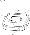
- the power base (40) of the payment terminal comprises, according to this embodiment of the invention, guiding means (41) of the payment terminal to a supply position of said payment terminal.
- the guiding means are arranged in such a way as to be inserted, or to penetrate, in means for receiving a memory card, for example a smart card, provided in an opening of the terminal of the payment terminal, because of their specific form similar to a memory card.
- a memory card for example a smart card
- These guide means are positioned in a concave part, here a hollow (43) formed in the feed base, thus allowing the terminal to reach a feed position when it is housed in the hollow of the base, position in which it is stably maintained by the cooperation of the recess and guide means.
- the means for receiving a memory card are efficiently exploited. Indeed, the same means allow, firstly, classically, the insertion of a memory card, and secondly, according to the invention, the electrical charging of the device, without it being necessary to provide a specific socket on this device.
- the electrical contacts for charging are arranged so as not to interfere with the use of the memory card, and for example on the sides of the receiving means.
- the guiding means (41) comprise feed means (42), arranged to cooperate, in a feed position, with contacts of the payment terminal, enabling the connection to a power supply.
- the supply means are metal parts, positioned on each side of the guide means (41), as illustrated in FIG. figure 2 .
- the supply means on the base cooperate with contacts of the terminal, thus ensuring the charging of the terminal battery.
- the contacts (50) are positioned on either side of the input of the smart card reader (51) of the terminal, thus enabling the terminal to be powered when the latter is in the position of feeding on the base.
- the guide means (41) of the base being inserted into the card reader (51) of the terminal, the terminal resting on the recess (43) of the base, the feed means (42) of the base co with the contacts of the terminal (50). These contacts are further used to discharge static electricity from the terminal.
- a particular embodiment of the invention is now described based on a new type of electronic payment terminal based on the physical pairing of a payment device with a communication terminal, such as a "smartphone", to form a payment terminal.
- This new type of terminal aims to overcome the disadvantages of the prior art and in particular allows not to use a dedicated telephone line to make a connection to the communication network and servers such as authorization servers or bank servers .
- the most recent terminals are connected to cash registers and / or computers via a communication network.
- Such connections may be wired, for example Ethernet, or wireless.
- These connections make it possible, for example, to connect to an authentication server or to a banking server in order to obtain debit authorization.
- the payment terminal uses a means of connection.
- One of these means is to use a wireless communication network, for example GPRS (General Packet Radio Service).
- the payment terminal is then equipped with a SIM card ( Subscriber Identity Module ). This is a chip containing a microcontroller and memory. This SIM card is associated with a telephone subscription (of data transmission type) which must be subscribed by the merchant.
- the implementation of the communication functionalities is attributed to the terminal.
- the terminal In addition to the fact that this type of subscription is relatively expensive, the implementation of the communication functionalities is attributed to the terminal.
- the terminal In addition to the payment functions, the terminal must manage communication functions, which are not naturally the functions expected of a payment terminal.
- WiFi Wireless Fidelity
- the merchant is no longer obliged to subscribe to a particular subscription.
- the payment terminal can connect to the merchant WiFi network and access, as in a wired connection, to the bank servers.
- the use of the terminal is then limited to the coverage area of the WiFi network, which is not suitable for nomadic use (for example a doctor visiting his patients).
- the electronic payment terminal according to this embodiment of the invention does not have these disadvantages of the prior art.
- the invention according to this embodiment relates more particularly to a payment terminal which is in the form of a device called "payment" which is physically paired with a communication terminal.
- the communication terminal to which the payment device is paired is a mobile terminal, commonly called “smartphone” (English), that is to say a mobile phone also having functions of a digital assistant Personnel (PDA).
- a mobile terminal commonly called “smartphone” (English)
- PDA digital assistant Personnel
- the invention overcomes the disadvantages of the prior art and in particular allows not to use a dedicated telephone line to make a connection to the communication network and servers such as authorization servers or bank servers .
- the payment terminal according to the invention has an asymmetrical structure, and therefore a particular positioning of its supply means.
- the power supply base according to the invention makes it possible to take account of the particular asymmetrical structure of the payment terminal according to the invention.
- the payment device is physically paired with the communication terminal via a particular pairing structure, called a modular interface.
- a particular pairing structure called a modular interface.
- this modular interface is attached to a back side of the payment device.
- This structure is removable, according to a particular embodiment of the invention, by implementing a particular kinematic.
- This modular interface allows to insert and retain the communication terminal in a housing provided for this purpose.
- a pairing device also called electronic connection card, for making a physical connection between the payment device and the communication terminal.
- This modular interface comprises other elements, which, according to the invention, provide a secure use of the payment terminal formed by the payment device and the communication terminal.
- the payment terminal (10) comprises two general components that are the payment device (20) and the communication terminal (30).
- the payment device (20) comprises a front face, visible on the Figure 1B , presenting a keyboard for entering information (21-1) and a display screen (21-2) of the information entered.
- the payment device comprises, on the rear face, visible on the figure 1D a surface (22) for attaching a modular interface (60) for pairing the communication terminal (30).
- this modular interface defines a housing (60-1) for insertion and pairing of the communication terminal (30).
- the figure 2 already described above, presents an example of a power supply base for such a payment terminal, according to one embodiment of the invention.
- the guiding means also serve as a key to the user of the terminal and allow him to properly position the payment terminal on the base, so as to ensure the proper operation of the power supply.
- the figure 3 also described above, illustrates an example of contacts for the supply of such a payment terminal comprising a pairing of two devices.
Landscapes
- Engineering & Computer Science (AREA)
- Theoretical Computer Science (AREA)
- Power Engineering (AREA)
- Computer Hardware Design (AREA)
- Human Computer Interaction (AREA)
- Physics & Mathematics (AREA)
- General Engineering & Computer Science (AREA)
- General Physics & Mathematics (AREA)
- Cash Registers Or Receiving Machines (AREA)
- Power Sources (AREA)
Claims (4)
- Stromversorgungsbasis (40) für ein Zahlungsterminal (10), dessen Gehäuse einen Eingang eines Chipkartenlesers aufweist, wobei der Eingang geeignet ist, eine Chipkarte aufzunehmen, wobei die Stromversorgungsbasis Mittel zum Führen (41) des Zahlungsterminals in Richtung einer Stromversorgungsposition des Zahlungsterminals aufweist, wobei die Mittel zum Führen mindestens einen Führungsabschnitt aufweisen, dessen Form geeignet ist, sein Einfügen in den Eingang des Chipkartenlesers des Zahlungsterminals (10) zu ermöglichen.
- Stromversorgungsbasis nach Anspruch 1, dadurch gekennzeichnet, dass der Führungsabschnitt (41) einen Vorsprung aufweist, der sich ausgehend von der Stromversorgungsbasis erstreckt, der eine Form aufweist, die für eine Chipkarte repräsentativ ist.
- Stromversorgungsbasis nach Anspruch 1, dadurch gekennzeichnet, dass die Mittel zum Führen (41) Stromversorgungsmittel (42) aufweisen, die ausgebildet sind, um mit nicht bündigen Kontakten des Zahlungsterminals (10) in der Stromversorgungsposition zusammenzuwirken.
- Stromversorgungsbasis nach Anspruch 3, dadurch gekennzeichnet, dass die Stromversorgungsmittel (42) mindestens ein Metallteil aufweisen, das auf jeder Seite der Mittel zum Führen angeordnet ist, wobei jedes Metallteil mit einem Kontakt des Zahlungsterminals (10) zusammenwirkt.
Priority Applications (1)
| Application Number | Priority Date | Filing Date | Title |
|---|---|---|---|
| PL11793433T PL2649698T3 (pl) | 2010-12-07 | 2011-12-07 | Baza zasilająca dla terminala do płatności elektronicznych |
Applications Claiming Priority (3)
| Application Number | Priority Date | Filing Date | Title |
|---|---|---|---|
| FR1060204A FR2968433B1 (fr) | 2010-12-07 | 2010-12-07 | Dispositif de paiement electronique apte a recevoir et maintenir un telephone portable. |
| FR1060206A FR2968419B1 (fr) | 2010-12-07 | 2010-12-07 | Base d'alimentation pour terminal de paiement electronique et terminal de paiement electronique. |
| PCT/EP2011/072003 WO2012076569A2 (fr) | 2010-12-07 | 2011-12-07 | Base d'alimentation pour terminal de paiement électronique et terminal de paiement électronique. |
Publications (2)
| Publication Number | Publication Date |
|---|---|
| EP2649698A2 EP2649698A2 (de) | 2013-10-16 |
| EP2649698B1 true EP2649698B1 (de) | 2019-03-27 |
Family
ID=45217560
Family Applications (1)
| Application Number | Title | Priority Date | Filing Date |
|---|---|---|---|
| EP11793433.1A Active EP2649698B1 (de) | 2010-12-07 | 2011-12-07 | Stromversorgungsbasis für ein elektronisches zahlungsterminal |
Country Status (8)
| Country | Link |
|---|---|
| US (1) | US9213369B2 (de) |
| EP (1) | EP2649698B1 (de) |
| AU (1) | AU2011340557B2 (de) |
| BR (1) | BR112013014114A2 (de) |
| CA (1) | CA2819863C (de) |
| ES (1) | ES2732294T3 (de) |
| PL (1) | PL2649698T3 (de) |
| WO (1) | WO2012076569A2 (de) |
Families Citing this family (1)
| Publication number | Priority date | Publication date | Assignee | Title |
|---|---|---|---|---|
| DE112022006619T5 (de) * | 2022-03-10 | 2024-12-05 | Qorum, Inc. | Tragbares mobiles Zahlungsabwicklungssystem und Hülle |
Family Cites Families (14)
| Publication number | Priority date | Publication date | Assignee | Title |
|---|---|---|---|---|
| US5109540A (en) | 1989-05-01 | 1992-04-28 | Motorola, Inc. | Radio and electronic card assembly |
| DE69324445T2 (de) | 1992-11-27 | 1999-09-30 | Denso Corp., Kariya | Tragbares elektronisches Gerät |
| US5933812A (en) * | 1995-04-12 | 1999-08-03 | Verifone Inc. | Portable transaction terminal system |
| US6653813B2 (en) * | 2002-03-21 | 2003-11-25 | Thomson Licensing, S.A. | Apparatus and method for the power management of operatively connected modular devices |
| US20040104268A1 (en) | 2002-07-30 | 2004-06-03 | Bailey Kenneth Stephen | Plug in credit card reader module for wireless cellular phone verifications |
| US7669829B2 (en) | 2004-03-05 | 2010-03-02 | Nec Corporation | Cradle device for portable terminal |
| US7240836B2 (en) | 2004-04-23 | 2007-07-10 | Virtual Fonlink, Inc. | Enhanced system and method for wireless transactions |
| US7309012B2 (en) | 2004-09-07 | 2007-12-18 | Semtek Innovative Solutions, Inc. | Secure magnetic stripe reader for handheld computing and method of using same |
| US8229501B2 (en) * | 2004-09-09 | 2012-07-24 | Dana Innovations | Computer wall docking station |
| US20060178967A1 (en) | 2005-02-04 | 2006-08-10 | Searete Llc | Disposition of proprietary virtual rights |
| US20060279251A1 (en) * | 2005-06-10 | 2006-12-14 | Guyot Nicolas E | Adjustable charger |
| US7580255B2 (en) * | 2005-08-24 | 2009-08-25 | Apple Inc. | Docking station for hand held electronic devices |
| US8559171B2 (en) * | 2008-02-22 | 2013-10-15 | Hewlett-Packard Development Company, L.P. | Docking station, and associated methodology, for a mini personal computer |
| US7751185B2 (en) * | 2008-09-16 | 2010-07-06 | Amtek System Co., Ltd. | Docking station applied to a portable electronic device |
-
2011
- 2011-12-07 EP EP11793433.1A patent/EP2649698B1/de active Active
- 2011-12-07 AU AU2011340557A patent/AU2011340557B2/en not_active Ceased
- 2011-12-07 PL PL11793433T patent/PL2649698T3/pl unknown
- 2011-12-07 CA CA2819863A patent/CA2819863C/en active Active
- 2011-12-07 BR BR112013014114A patent/BR112013014114A2/pt not_active Application Discontinuation
- 2011-12-07 WO PCT/EP2011/072003 patent/WO2012076569A2/fr not_active Ceased
- 2011-12-07 US US13/992,360 patent/US9213369B2/en active Active
- 2011-12-07 ES ES11793433T patent/ES2732294T3/es active Active
Non-Patent Citations (1)
| Title |
|---|
| None * |
Also Published As
| Publication number | Publication date |
|---|---|
| EP2649698A2 (de) | 2013-10-16 |
| WO2012076569A2 (fr) | 2012-06-14 |
| PL2649698T3 (pl) | 2019-09-30 |
| CA2819863A1 (en) | 2012-06-14 |
| CA2819863C (en) | 2020-02-04 |
| US9213369B2 (en) | 2015-12-15 |
| US20140321047A1 (en) | 2014-10-30 |
| BR112013014114A2 (pt) | 2016-09-20 |
| WO2012076569A3 (fr) | 2012-08-09 |
| AU2011340557A1 (en) | 2013-07-18 |
| ES2732294T3 (es) | 2019-11-21 |
| AU2011340557B2 (en) | 2016-03-10 |
Similar Documents
| Publication | Publication Date | Title |
|---|---|---|
| EP2175565A1 (de) | Schutzhülle für tragbares elektronisches Gerät | |
| EP2097989A1 (de) | Lokale rf-kommunikationsschnittstelle zwischen einem mobiltelefon und einem kontaktlosen lesegerät | |
| EP0840247B1 (de) | Mit einem Speicherkartenleser versehenes Funkmodem | |
| WO2009083658A1 (fr) | Distribution de titres électroniques par radiofréquence | |
| WO2012076573A1 (fr) | Dispositif de paiement électronique apte à recevoir et maintenir un téléphone portable | |
| EP1483724A2 (de) | Verfahren zur verwaltung von auf einer mobiltelefonlesbaren chipkarte gespeicherten informationen | |
| EP2649699B1 (de) | Verfahren zur verwaltung des ladezustandes von mindestens zwei batterien, vorrichtung und computerprogramm dafür | |
| EP3320503A1 (de) | Aktive peripherievorrichtung und elektronisches zahlungsendgerät | |
| WO2012076569A2 (fr) | Base d'alimentation pour terminal de paiement électronique et terminal de paiement électronique. | |
| EP3543894A1 (de) | Aufnahmeständer für mobiles endgerät, und entsprechendes mobiles endgerät | |
| CA2984556A1 (fr) | Terminal de paiement integrant des moyens de communication sans fil | |
| EP2649777B1 (de) | Elektronische bezahlungsvorrichtung | |
| FR2968419A1 (fr) | Base d'alimentation pour terminal de paiement electronique et terminal de paiement electronique. | |
| EP2577800A1 (de) | Antenne für ein nfc-gerät | |
| EP2649779B1 (de) | Modulare schnittstelle eines elektronischen zahlungsterminals mit beweglichkeit einer abdeckung durch verschiebung und drehung | |
| WO2001097161A1 (fr) | Portefeuille electronique de cartes a puce | |
| WO2020012077A1 (fr) | Réceptacle portable de transaction | |
| EP2649780B1 (de) | Zahlungsterminal mit einer zahlungsvorrichtung und einer modularen schnittstelle in form einer abdeckung oder haube zur paarung eines kommunikationsendgeräts | |
| FR2903545A1 (fr) | Distribution de titres electroniques par radiofrequence | |
| FR2968478A1 (fr) | Procede de gestion du niveau de charge d'au moins deux batteries, dispositif et programme d'ordinateur correspondants. | |
| FR2968434A1 (fr) | Dispositif de paiement electronique. | |
| OA21562A (fr) | Terminal portable de transactions financières. | |
| FR2968492A1 (fr) | Terminal de paiement comprenant un dispositif de paiement et une interface modulaire formant capot ou etui pour appairer un terminal de communication. | |
| FR2968491A1 (fr) | Interface modulaire comprise dans un terminal de paiement electronique, avec articulation d'un couvercle par translation et rotation. |
Legal Events
| Date | Code | Title | Description |
|---|---|---|---|
| PUAI | Public reference made under article 153(3) epc to a published international application that has entered the european phase |
Free format text: ORIGINAL CODE: 0009012 |
|
| 17P | Request for examination filed |
Effective date: 20130624 |
|
| AK | Designated contracting states |
Kind code of ref document: A2 Designated state(s): AL AT BE BG CH CY CZ DE DK EE ES FI FR GB GR HR HU IE IS IT LI LT LU LV MC MK MT NL NO PL PT RO RS SE SI SK SM TR |
|
| DAX | Request for extension of the european patent (deleted) | ||
| RAP1 | Party data changed (applicant data changed or rights of an application transferred) |
Owner name: INGENICO GROUP |
|
| STAA | Information on the status of an ep patent application or granted ep patent |
Free format text: STATUS: EXAMINATION IS IN PROGRESS |
|
| 17Q | First examination report despatched |
Effective date: 20180523 |
|
| GRAP | Despatch of communication of intention to grant a patent |
Free format text: ORIGINAL CODE: EPIDOSNIGR1 |
|
| STAA | Information on the status of an ep patent application or granted ep patent |
Free format text: STATUS: GRANT OF PATENT IS INTENDED |
|
| RIC1 | Information provided on ipc code assigned before grant |
Ipc: G06F 1/16 20060101ALI20181002BHEP Ipc: H02J 7/00 20060101AFI20181002BHEP Ipc: H04M 1/04 20060101ALI20181002BHEP |
|
| INTG | Intention to grant announced |
Effective date: 20181025 |
|
| GRAS | Grant fee paid |
Free format text: ORIGINAL CODE: EPIDOSNIGR3 |
|
| GRAA | (expected) grant |
Free format text: ORIGINAL CODE: 0009210 |
|
| STAA | Information on the status of an ep patent application or granted ep patent |
Free format text: STATUS: THE PATENT HAS BEEN GRANTED |
|
| AK | Designated contracting states |
Kind code of ref document: B1 Designated state(s): AL AT BE BG CH CY CZ DE DK EE ES FI FR GB GR HR HU IE IS IT LI LT LU LV MC MK MT NL NO PL PT RO RS SE SI SK SM TR |
|
| REG | Reference to a national code |
Ref country code: GB Ref legal event code: FG4D Free format text: NOT ENGLISH |
|
| REG | Reference to a national code |
Ref country code: CH Ref legal event code: EP |
|
| REG | Reference to a national code |
Ref country code: AT Ref legal event code: REF Ref document number: 1114187 Country of ref document: AT Kind code of ref document: T Effective date: 20190415 |
|
| REG | Reference to a national code |
Ref country code: IE Ref legal event code: FG4D Free format text: LANGUAGE OF EP DOCUMENT: FRENCH |
|
| REG | Reference to a national code |
Ref country code: DE Ref legal event code: R096 Ref document number: 602011057570 Country of ref document: DE |
|
| PG25 | Lapsed in a contracting state [announced via postgrant information from national office to epo] |
Ref country code: NO Free format text: LAPSE BECAUSE OF FAILURE TO SUBMIT A TRANSLATION OF THE DESCRIPTION OR TO PAY THE FEE WITHIN THE PRESCRIBED TIME-LIMIT Effective date: 20190627 Ref country code: FI Free format text: LAPSE BECAUSE OF FAILURE TO SUBMIT A TRANSLATION OF THE DESCRIPTION OR TO PAY THE FEE WITHIN THE PRESCRIBED TIME-LIMIT Effective date: 20190327 Ref country code: SE Free format text: LAPSE BECAUSE OF FAILURE TO SUBMIT A TRANSLATION OF THE DESCRIPTION OR TO PAY THE FEE WITHIN THE PRESCRIBED TIME-LIMIT Effective date: 20190327 Ref country code: LT Free format text: LAPSE BECAUSE OF FAILURE TO SUBMIT A TRANSLATION OF THE DESCRIPTION OR TO PAY THE FEE WITHIN THE PRESCRIBED TIME-LIMIT Effective date: 20190327 |
|
| REG | Reference to a national code |
Ref country code: NL Ref legal event code: MP Effective date: 20190327 |
|
| PG25 | Lapsed in a contracting state [announced via postgrant information from national office to epo] |
Ref country code: HR Free format text: LAPSE BECAUSE OF FAILURE TO SUBMIT A TRANSLATION OF THE DESCRIPTION OR TO PAY THE FEE WITHIN THE PRESCRIBED TIME-LIMIT Effective date: 20190327 Ref country code: NL Free format text: LAPSE BECAUSE OF FAILURE TO SUBMIT A TRANSLATION OF THE DESCRIPTION OR TO PAY THE FEE WITHIN THE PRESCRIBED TIME-LIMIT Effective date: 20190327 Ref country code: LV Free format text: LAPSE BECAUSE OF FAILURE TO SUBMIT A TRANSLATION OF THE DESCRIPTION OR TO PAY THE FEE WITHIN THE PRESCRIBED TIME-LIMIT Effective date: 20190327 Ref country code: BG Free format text: LAPSE BECAUSE OF FAILURE TO SUBMIT A TRANSLATION OF THE DESCRIPTION OR TO PAY THE FEE WITHIN THE PRESCRIBED TIME-LIMIT Effective date: 20190627 Ref country code: RS Free format text: LAPSE BECAUSE OF FAILURE TO SUBMIT A TRANSLATION OF THE DESCRIPTION OR TO PAY THE FEE WITHIN THE PRESCRIBED TIME-LIMIT Effective date: 20190327 |
|
| REG | Reference to a national code |
Ref country code: AT Ref legal event code: MK05 Ref document number: 1114187 Country of ref document: AT Kind code of ref document: T Effective date: 20190327 |
|
| REG | Reference to a national code |
Ref country code: GR Ref legal event code: EP Ref document number: 20190401725 Country of ref document: GR Effective date: 20190906 |
|
| PG25 | Lapsed in a contracting state [announced via postgrant information from national office to epo] |
Ref country code: EE Free format text: LAPSE BECAUSE OF FAILURE TO SUBMIT A TRANSLATION OF THE DESCRIPTION OR TO PAY THE FEE WITHIN THE PRESCRIBED TIME-LIMIT Effective date: 20190327 Ref country code: RO Free format text: LAPSE BECAUSE OF FAILURE TO SUBMIT A TRANSLATION OF THE DESCRIPTION OR TO PAY THE FEE WITHIN THE PRESCRIBED TIME-LIMIT Effective date: 20190327 Ref country code: AL Free format text: LAPSE BECAUSE OF FAILURE TO SUBMIT A TRANSLATION OF THE DESCRIPTION OR TO PAY THE FEE WITHIN THE PRESCRIBED TIME-LIMIT Effective date: 20190327 Ref country code: CZ Free format text: LAPSE BECAUSE OF FAILURE TO SUBMIT A TRANSLATION OF THE DESCRIPTION OR TO PAY THE FEE WITHIN THE PRESCRIBED TIME-LIMIT Effective date: 20190327 Ref country code: SK Free format text: LAPSE BECAUSE OF FAILURE TO SUBMIT A TRANSLATION OF THE DESCRIPTION OR TO PAY THE FEE WITHIN THE PRESCRIBED TIME-LIMIT Effective date: 20190327 Ref country code: PT Free format text: LAPSE BECAUSE OF FAILURE TO SUBMIT A TRANSLATION OF THE DESCRIPTION OR TO PAY THE FEE WITHIN THE PRESCRIBED TIME-LIMIT Effective date: 20190727 |
|
| REG | Reference to a national code |
Ref country code: ES Ref legal event code: FG2A Ref document number: 2732294 Country of ref document: ES Kind code of ref document: T3 Effective date: 20191121 |
|
| PG25 | Lapsed in a contracting state [announced via postgrant information from national office to epo] |
Ref country code: SM Free format text: LAPSE BECAUSE OF FAILURE TO SUBMIT A TRANSLATION OF THE DESCRIPTION OR TO PAY THE FEE WITHIN THE PRESCRIBED TIME-LIMIT Effective date: 20190327 |
|
| PG25 | Lapsed in a contracting state [announced via postgrant information from national office to epo] |
Ref country code: AT Free format text: LAPSE BECAUSE OF FAILURE TO SUBMIT A TRANSLATION OF THE DESCRIPTION OR TO PAY THE FEE WITHIN THE PRESCRIBED TIME-LIMIT Effective date: 20190327 Ref country code: IS Free format text: LAPSE BECAUSE OF FAILURE TO SUBMIT A TRANSLATION OF THE DESCRIPTION OR TO PAY THE FEE WITHIN THE PRESCRIBED TIME-LIMIT Effective date: 20190727 |
|
| REG | Reference to a national code |
Ref country code: DE Ref legal event code: R097 Ref document number: 602011057570 Country of ref document: DE |
|
| PG25 | Lapsed in a contracting state [announced via postgrant information from national office to epo] |
Ref country code: DK Free format text: LAPSE BECAUSE OF FAILURE TO SUBMIT A TRANSLATION OF THE DESCRIPTION OR TO PAY THE FEE WITHIN THE PRESCRIBED TIME-LIMIT Effective date: 20190327 |
|
| PLBE | No opposition filed within time limit |
Free format text: ORIGINAL CODE: 0009261 |
|
| STAA | Information on the status of an ep patent application or granted ep patent |
Free format text: STATUS: NO OPPOSITION FILED WITHIN TIME LIMIT |
|
| PG25 | Lapsed in a contracting state [announced via postgrant information from national office to epo] |
Ref country code: SI Free format text: LAPSE BECAUSE OF FAILURE TO SUBMIT A TRANSLATION OF THE DESCRIPTION OR TO PAY THE FEE WITHIN THE PRESCRIBED TIME-LIMIT Effective date: 20190327 |
|
| 26N | No opposition filed |
Effective date: 20200103 |
|
| PG25 | Lapsed in a contracting state [announced via postgrant information from national office to epo] |
Ref country code: TR Free format text: LAPSE BECAUSE OF FAILURE TO SUBMIT A TRANSLATION OF THE DESCRIPTION OR TO PAY THE FEE WITHIN THE PRESCRIBED TIME-LIMIT Effective date: 20190327 |
|
| REG | Reference to a national code |
Ref country code: CH Ref legal event code: PL |
|
| REG | Reference to a national code |
Ref country code: BE Ref legal event code: MM Effective date: 20191231 |
|
| PG25 | Lapsed in a contracting state [announced via postgrant information from national office to epo] |
Ref country code: MC Free format text: LAPSE BECAUSE OF FAILURE TO SUBMIT A TRANSLATION OF THE DESCRIPTION OR TO PAY THE FEE WITHIN THE PRESCRIBED TIME-LIMIT Effective date: 20190327 |
|
| PG25 | Lapsed in a contracting state [announced via postgrant information from national office to epo] |
Ref country code: IE Free format text: LAPSE BECAUSE OF NON-PAYMENT OF DUE FEES Effective date: 20191207 Ref country code: LU Free format text: LAPSE BECAUSE OF NON-PAYMENT OF DUE FEES Effective date: 20191207 |
|
| PG25 | Lapsed in a contracting state [announced via postgrant information from national office to epo] |
Ref country code: LI Free format text: LAPSE BECAUSE OF NON-PAYMENT OF DUE FEES Effective date: 20191231 Ref country code: CH Free format text: LAPSE BECAUSE OF NON-PAYMENT OF DUE FEES Effective date: 20191231 Ref country code: BE Free format text: LAPSE BECAUSE OF NON-PAYMENT OF DUE FEES Effective date: 20191231 |
|
| PG25 | Lapsed in a contracting state [announced via postgrant information from national office to epo] |
Ref country code: CY Free format text: LAPSE BECAUSE OF FAILURE TO SUBMIT A TRANSLATION OF THE DESCRIPTION OR TO PAY THE FEE WITHIN THE PRESCRIBED TIME-LIMIT Effective date: 20190327 |
|
| PG25 | Lapsed in a contracting state [announced via postgrant information from national office to epo] |
Ref country code: MT Free format text: LAPSE BECAUSE OF FAILURE TO SUBMIT A TRANSLATION OF THE DESCRIPTION OR TO PAY THE FEE WITHIN THE PRESCRIBED TIME-LIMIT Effective date: 20190327 Ref country code: HU Free format text: LAPSE BECAUSE OF FAILURE TO SUBMIT A TRANSLATION OF THE DESCRIPTION OR TO PAY THE FEE WITHIN THE PRESCRIBED TIME-LIMIT; INVALID AB INITIO Effective date: 20111207 |
|
| REG | Reference to a national code |
Ref country code: GB Ref legal event code: 732E Free format text: REGISTERED BETWEEN 20220127 AND 20220202 |
|
| PG25 | Lapsed in a contracting state [announced via postgrant information from national office to epo] |
Ref country code: MK Free format text: LAPSE BECAUSE OF FAILURE TO SUBMIT A TRANSLATION OF THE DESCRIPTION OR TO PAY THE FEE WITHIN THE PRESCRIBED TIME-LIMIT Effective date: 20190327 |
|
| REG | Reference to a national code |
Ref country code: DE Ref legal event code: R081 Ref document number: 602011057570 Country of ref document: DE Owner name: BANKS AND ACQUIRES INTERNATIONAL HOLDING, FR Free format text: FORMER OWNER: INGENICO GROUP, PARIS, FR Ref country code: DE Ref legal event code: R082 Ref document number: 602011057570 Country of ref document: DE Representative=s name: STUMPF PATENTANWAELTE PARTGMBB, DE Ref country code: DE Ref legal event code: R081 Ref document number: 602011057570 Country of ref document: DE Owner name: BANKS AND ACQUIRERS INTERNATIONAL HOLDING, FR Free format text: FORMER OWNER: INGENICO GROUP, PARIS, FR |
|
| REG | Reference to a national code |
Ref country code: DE Ref legal event code: R081 Ref document number: 602011057570 Country of ref document: DE Owner name: BANKS AND ACQUIRERS INTERNATIONAL HOLDING, FR Free format text: FORMER OWNER: BANKS AND ACQUIRES INTERNATIONAL HOLDING, SURESNES, FR |
|
| REG | Reference to a national code |
Ref country code: ES Ref legal event code: PC2A Owner name: BANKS AND ACQUIRERS INTERNATIONAL HOLDING Effective date: 20250926 |
|
| PGFP | Annual fee paid to national office [announced via postgrant information from national office to epo] |
Ref country code: DE Payment date: 20251211 Year of fee payment: 15 |
|
| PGFP | Annual fee paid to national office [announced via postgrant information from national office to epo] |
Ref country code: GB Payment date: 20251219 Year of fee payment: 15 |
|
| PGFP | Annual fee paid to national office [announced via postgrant information from national office to epo] |
Ref country code: IT Payment date: 20251223 Year of fee payment: 15 |
|
| PGFP | Annual fee paid to national office [announced via postgrant information from national office to epo] |
Ref country code: FR Payment date: 20251230 Year of fee payment: 15 |
|
| PGFP | Annual fee paid to national office [announced via postgrant information from national office to epo] |
Ref country code: GR Payment date: 20251222 Year of fee payment: 15 |
|
| PGFP | Annual fee paid to national office [announced via postgrant information from national office to epo] |
Ref country code: PL Payment date: 20251120 Year of fee payment: 15 |
|
| P01 | Opt-out of the competence of the unified patent court (upc) registered |
Free format text: CASE NUMBER: UPC_APP_0000322_2649698/2026 Effective date: 20260106 |
|
| PGFP | Annual fee paid to national office [announced via postgrant information from national office to epo] |
Ref country code: ES Payment date: 20260130 Year of fee payment: 15 |