EP2649738B1 - Vorrichtung zur stream-auswahl bei digitalen diensten sowie verfahren, computerprogramm und speichervorrichtung dafür - Google Patents
Vorrichtung zur stream-auswahl bei digitalen diensten sowie verfahren, computerprogramm und speichervorrichtung dafür Download PDFInfo
- Publication number
- EP2649738B1 EP2649738B1 EP11791554.6A EP11791554A EP2649738B1 EP 2649738 B1 EP2649738 B1 EP 2649738B1 EP 11791554 A EP11791554 A EP 11791554A EP 2649738 B1 EP2649738 B1 EP 2649738B1
- Authority
- EP
- European Patent Office
- Prior art keywords
- digital service
- stream
- streams
- modulator
- t2mi
- Prior art date
- Legal status (The legal status is an assumption and is not a legal conclusion. Google has not performed a legal analysis and makes no representation as to the accuracy of the status listed.)
- Active
Links
Images



Classifications
-
- H—ELECTRICITY
- H04—ELECTRIC COMMUNICATION TECHNIQUE
- H04L—TRANSMISSION OF DIGITAL INFORMATION, e.g. TELEGRAPHIC COMMUNICATION
- H04L65/00—Network arrangements, protocols or services for supporting real-time applications in data packet communication
- H04L65/60—Network streaming of media packets
-
- H—ELECTRICITY
- H04—ELECTRIC COMMUNICATION TECHNIQUE
- H04H—BROADCAST COMMUNICATION
- H04H20/00—Arrangements for broadcast or for distribution combined with broadcast
- H04H20/10—Arrangements for replacing or switching information during the broadcast or the distribution
- H04H20/103—Transmitter-side switching
-
- H—ELECTRICITY
- H04—ELECTRIC COMMUNICATION TECHNIQUE
- H04L—TRANSMISSION OF DIGITAL INFORMATION, e.g. TELEGRAPHIC COMMUNICATION
- H04L65/00—Network arrangements, protocols or services for supporting real-time applications in data packet communication
- H04L65/60—Network streaming of media packets
- H04L65/61—Network streaming of media packets for supporting one-way streaming services, e.g. Internet radio
- H04L65/611—Network streaming of media packets for supporting one-way streaming services, e.g. Internet radio for multicast or broadcast
-
- H—ELECTRICITY
- H04—ELECTRIC COMMUNICATION TECHNIQUE
- H04N—PICTORIAL COMMUNICATION, e.g. TELEVISION
- H04N21/00—Selective content distribution, e.g. interactive television or video on demand [VOD]
- H04N21/20—Servers specifically adapted for the distribution of content, e.g. VOD servers; Operations thereof
- H04N21/23—Processing of content or additional data; Elementary server operations; Server middleware
- H04N21/238—Interfacing the downstream path of the transmission network, e.g. adapting the transmission rate of a video stream to network bandwidth; Processing of multiplex streams
- H04N21/2389—Multiplex stream processing, e.g. multiplex stream encrypting
-
- H—ELECTRICITY
- H04—ELECTRIC COMMUNICATION TECHNIQUE
- H04N—PICTORIAL COMMUNICATION, e.g. TELEVISION
- H04N21/00—Selective content distribution, e.g. interactive television or video on demand [VOD]
- H04N21/20—Servers specifically adapted for the distribution of content, e.g. VOD servers; Operations thereof
- H04N21/23—Processing of content or additional data; Elementary server operations; Server middleware
- H04N21/24—Monitoring of processes or resources, e.g. monitoring of server load, available bandwidth, upstream requests
- H04N21/2404—Monitoring of server processing errors or hardware failure
-
- H—ELECTRICITY
- H04—ELECTRIC COMMUNICATION TECHNIQUE
- H04N—PICTORIAL COMMUNICATION, e.g. TELEVISION
- H04N21/00—Selective content distribution, e.g. interactive television or video on demand [VOD]
- H04N21/20—Servers specifically adapted for the distribution of content, e.g. VOD servers; Operations thereof
- H04N21/23—Processing of content or additional data; Elementary server operations; Server middleware
- H04N21/242—Synchronisation processes, e.g. processing of PCR [Programme Clock References]
-
- H—ELECTRICITY
- H04—ELECTRIC COMMUNICATION TECHNIQUE
- H04N—PICTORIAL COMMUNICATION, e.g. TELEVISION
- H04N21/00—Selective content distribution, e.g. interactive television or video on demand [VOD]
- H04N21/40—Client devices specifically adapted for the reception of or interaction with content, e.g. set-top-box [STB]; Operations thereof
- H04N21/43—Processing of content or additional data, e.g. demultiplexing additional data from a digital video stream; Elementary client operations, e.g. monitoring of home network or synchronising decoder's clock; Client middleware
- H04N21/438—Interfacing the downstream path of the transmission network originating from a server, e.g. retrieving encoded video stream packets from an IP network
- H04N21/4385—Multiplex stream processing, e.g. multiplex stream decrypting
-
- H—ELECTRICITY
- H04—ELECTRIC COMMUNICATION TECHNIQUE
- H04N—PICTORIAL COMMUNICATION, e.g. TELEVISION
- H04N21/00—Selective content distribution, e.g. interactive television or video on demand [VOD]
- H04N21/60—Network structure or processes for video distribution between server and client or between remote clients; Control signalling between clients, server and network components; Transmission of management data between server and client, e.g. sending from server to client commands for recording incoming content stream; Communication details between server and client
- H04N21/63—Control signaling related to video distribution between client, server and network components; Network processes for video distribution between server and clients or between remote clients, e.g. transmitting basic layer and enhancement layers over different transmission paths, setting up a peer-to-peer communication via Internet between remote STB's; Communication protocols; Addressing
- H04N21/631—Multimode Transmission, e.g. transmitting basic layers and enhancement layers of the content over different transmission paths or transmitting with different error corrections, different keys or with different transmission protocols
-
- H—ELECTRICITY
- H04—ELECTRIC COMMUNICATION TECHNIQUE
- H04H—BROADCAST COMMUNICATION
- H04H20/00—Arrangements for broadcast or for distribution combined with broadcast
- H04H20/65—Arrangements characterised by transmission systems for broadcast
- H04H20/67—Common-wave systems, i.e. using separate transmitters operating on substantially the same frequency
Definitions
- the present invention relates to the field of broadcasting digital services to delivery terminals of these services. More particularly, the present invention is concerned with the problem of the reliability of the broadcast chain.
- Digital service broadcasting networks are becoming widespread.
- DVB-T Digital Video Broadcasting - Terrestrial
- DVB Digital Video Broadcasting - Terrestrial
- ETSI EN 300 744 V1.5.1 Digital Video Broadcasting (DVB): Framing Structure, Channel Coding and Modulation for Digital Terrestrial Television
- DVB-H Digital Video Broadcasting - Handheld
- ETSI EN 302 304 DVB-H - Transmission System for Handheld Terminals
- the services are encoded individually by a set of encoders.
- Each of these encoders has the contents of the service for which it is responsible. Such content may be composed of video sequences, audio sequences, texts or interactive applications.
- each service is available in the form of a data stream number of packets.
- These services are then multiplexed by a multiplexer. This operation consists of building a stream mixing the data packets of the different services to be broadcast. This results in a digital data flow comprising the data of the different services.
- the MPEG-2 TS transport stream format ( Moving Picture Experts Group-2 Transport Stream in English) described in the document "ISO / IEC 13818-1, Generic Coding of Moving Pictures and Associated Audio Information Systems ", or the format according to the Internet Protocol IP ( Internet Protocol in English), can be used.
- the stream In the context of a radio transmission, the stream is intended to be transmitted in the form of a radio signal by one or more modulators. To do this, the stream must be formatted by a formatting module. This formatting may, for example, consist of the insertion of synchronization marks in the stream, so as to allow the modulator (s) to synchronize the transmission of the radio signal within the framework of a SFN type distribution ( Single Frequency Network in English or Network Frequency One french).
- the patent document WO 2009/112 371A1 describes a broadcast system with a duplicate formatting module.
- This broadcasting system allows a modulator to switch between the two streams generated by the two formatting modules without becoming out of sync.
- These formatting modules are synchronized with each other to generate synchronized flows.
- a modulator can switch from a first stream generated by one of the formatting modules to a second stream generated by the other formatting module, without a resynchronization of the modulator is necessary.
- an incident affecting the generation of the flow does not systematically result in service interruption.
- the broadcasting system described in this document WO 2009/112 371A1 is not suitable for implementation in the context of a broadcast based on the DVB-T2 second-generation digital video broadcast standard: "EN 302 755 VI.1.1, Frame Structure, Channel Coding and Modulation for a Second Generation Digital Terrestrial Television Broadcasting System ".
- the synchronization performed between the MPEG2 TS transport streams does not make it possible to avoid resynchronization at the level of the modulator in this frame.
- the patent document US 2007/023185 A1 describes a system for broadcasting multimedia streams, such as, for example, video streams in MPEG format.
- a source transmits to a recipient two redundant streams on two different paths in a communication network. These streams are received by a network edge device (“ Network edge device ”) to form a single stream to address the recipient.
- Network edge device a network edge device
- the patent document US 2003/142670 A1 describes a data stream delivery system.
- the system comprises a plurality of redundant servers transmitting the same data stream to a " failover device ".
- the reliability device stores the received streams and switches from a primary stream to a secondary stream in case of corruption of the primary stream.
- the patent document FR 2 936 919 A1 describes a digital service broadcasting system on a single modulation frequency, where fine synchronization devices are inserted upstream of emission points.
- the patent document US 6,765,865 B1 describes a switch that receives two identical video contents via two respective inputs. The switch switches from primary content to secondary content in case of disruption or interruption of the primary content.
- the invention relates to a device intended to be placed upstream of a modulator in a digital service flow broadcasting chain, said device comprising means for receiving a plurality of transport streams and transmission means of a transport stream to the modulator, each transport stream encapsulating a digital service stream adapted to be broadcast by said modulator, said digital service flows being representative of the same digital service, the device being such that it comprises: means for extracting digital service flows from the received transport streams; error detection means at the received transport streams and / or the extracted digital service stream; extracted digital service stream alignment means; means for selecting a stream among the aligned digital service flows, as a function of any errors detected by said detection means; and, means for encapsulating the selected digital service flow, in order to forming said transport stream to be transmitted to said modulator.
- a device intended to be placed upstream of a modulator in a digital service flow broadcasting chain, said device comprising means for receiving a plurality of transport streams and transmission means of a transport stream to the modulator, each transport stream encapsulating
- said alignment means comprise means for storing the packets of the digital service flows extracted in correspondence with respective packet type information and the respective values of a continuity counter of said packets within a packet. their respective digital service flows.
- alignment of digital service flows is facilitated.
- said alignment means comprise stored packet reading means, and said means being implemented to read a packet of a given digital service stream, said means are further enabled to read. a packet of another digital service stream, if their respective packet type information and their respective continuity counter values coincide.
- said storage means are adapted to store the packets of the extracted digital service flows in correspondence with information representative of instants at which said packets are respectively stored, and said reading means are further activated according to said information.
- encapsulation performed by the device to obtain a transport stream for the modulator is slaved to the timing of the selected digital service stream.
- said reading means are initially activated following the expiration of a predefined duration timer started when storing the first packet of said stream.
- a constant processing time is applied by the device.
- said selection means take into account a predefined priority order between said aligned digital service flows.
- the reliability of the transmission of the service is enhanced, for example by establishing this order of priority according to a level of robustness a priori transmissions of the transport stream until said device.
- the invention also relates to a digital service flow broadcasting system, said system being intended to transmit, to a modulator, a transport stream encapsulating a digital service flow adapted to be broadcast by said modulator, the system being such that it comprises a device, as mentioned previously, said flow selection device, and at least one provider device providing said plurality of transport streams to said stream selection device.
- the system comprises a plurality of supplier devices, and said provider devices comprise: means for assigning a master status to a given supplier device, a slave status being assigned to each other device provider ; respective means for generating digital service flows, said generation means of each slave device being temporally slaved to those of the master device.
- the invention also relates to a method implemented by a device intended to be placed upstream of a modulator in a digital service stream broadcasting chain, said device comprising means for receiving a plurality of transport streams and means for transmitting a transport stream to the modulator, each transport stream encapsulating a digital service stream adapted to be broadcast by said modulator, said digital service flows being representative of the same digital service, the method being such that it comprises steps of: extracting digital service flows from the transport streams received by said device; error detection at the received transport stream and / or the extracted digital service stream; digital service flow alignment schemes extracted; selecting a stream among the aligned digital service flows, as a function of any errors detected by said detection means; encapsulating the selected digital service stream to form said transport stream to be transmitted to said modulator.
- the invention also relates to a computer program, which can be stored on a medium and / or downloaded from a communication network, in order to be read by a computer system or a processor.
- This computer program includes instructions for implementing the method mentioned above, when said program is executed by a computer system or a processor.
- the invention also relates to storage means comprising such a computer program.
- This device comprises means for receiving a plurality of transport streams, each encapsulating a digital service flow as mentioned above.
- these digital service flows are T2MI flows.
- the device performs a digital service flow extraction from the received transport streams and detects any errors in the received transport streams, i.e. at the MPEG2 TS level within the framework of the DVB- standard.
- T and / or at extracts digital service flow, that is to say at T2MI level (T2 Modulator Interface Interface in English or French modulator T2) within the DVB-T2 standard.
- the device then aligns extracted digital service streams, and selects a stream among the aligned streams, based on any errors detected. Finally, the device encapsulates the selected stream to form the transport stream to be transmitted to the modulator. When the device subsequently detects errors in the selected stream, it selects another stream from among the aligned streams. In other words, he switches to this other stream.
- the Fig. 1 schematically illustrates a digital service broadcasting system, in which the present invention can be implemented.
- the dissemination system presented to the Fig. 1 complies with the DVB-T2 standard.
- Digital services are received in the form of at least one MPEG2 TS transport stream, called TS stream or TS packets thereafter, by 1.1 and 1.2 gateways via respective links 1.5 and 1.6.
- the broadcast system may have a larger number of gateways to make the broadcast chain more reliable.
- each gateway 1.1 and 1.2 builds BaseBand Frame (BB) frames from each received TS stream.
- BB BaseBand Frame
- the amount of useful data in the BB frames depends on the transmission parameters: constellation, coding rate ( code rate in English), FEC ( Forward Error Correction ) error correction data, etc.
- Gateways 1.1 and 1.2 then encapsulate the BB frames in T2MI packets.
- Gateways 1.1 and 1.2 also generate T2MI packet signaling and T2MI packets containing timestamp information (timestamp in English).
- Several types of T2MI packets are thus generated by the 1.1 and 1.2 gateways.
- T2MI packets are grouped by type T2 frames, the period of a T2 frame is defined by the OFDM modulation parameters (Orthogonal Frequency Division Multiplexing Multiplexing in English or orthogonal frequency division French) used.
- Each frame T2 comprises T2MI packets containing BB frames, then a T2MI packet of timestamp information, and then a signaling T2MI packet.
- the signaling T2MI package contains the L1 type information, ie it contains modulation information: bandwidth, FFT size (Fast Fourier Transform in English or Fast Fourier Transform French), etc.
- the information contained in the T2MI packet of timestamp information corresponds to an indication of the instant at which the superframe T2, composed of a predefined number of successive T2 frames, must be transmitted by each modulator in the case of a distribution.
- SFN type The timestamp information can be absolute using a common or relative start reference time, for example example compared to a PPS type timing ( Pulse Per Second in English or Pulse Per Second in French).
- PPS type timing Pulse Per Second in English or Pulse Per Second in French
- the timestamp information is not significant in the case of a type of distribution MFN (Multiple Frequency Network in English or in French Network Multiple Frequency).
- MFN Multiple Frequency Network in English or in French Network Multiple Frequency
- Gateways 1.1 and 1.2 encapsulate T2MI packets in TS packets to allow the transport of digital services to 1.4 modulators (only one of which is shown on the Fig. 1 ).
- PAT table Program Association Table in English or French Programs Association Table
- PMT Program Map Table in English or French in Correspondence Programs Table
- optionally stuffing packets also known as NULL packets are added in order to obtain a constant rate ETR 290 valid bit rate stream: " Digital Video Broadcasting (DVB); Measurement Guidelines for DVB Systems "and more specifically the” Measurement and Analysis of the MPEG-2 Transport Stream "section of this report.
- the gateways 1.1 and 1.2 thus perform a rate adaptation at the TS stream.
- the gateways 1.1 and 1.2 transmit the T2MI packets, encapsulated in TS packets, respectively via links 1.8 and 1.9.
- the links 1.8 and 1.9 may be of a different nature, for example the link 1.8 corresponds to a satellite communication and the link 1.9 corresponds to a communication via the Internet network.
- a data stream selection module 1.3 receives these T2MI packets, encapsulated in TS packets, via these links 1.8 and 1.9. This module 1.3 is in charge of dynamically selecting a stream among those from the 1.1 and 1.2 gateways and providing it to the modulator 1.4 via a link 1.10.
- the module 1.3 selects the stream coming from the other gateway.
- a flow switchover can take place when the flow that was previously selected has been interrupted.
- a synchronization at the superframe level T2 is then required, which means that the T2 superframes and T2 frames are transmitted at the same time and that the values of the continuity counters of the T2MI packets transmitted simultaneously by the gateways are identical; otherwise, switching from one stream to another would result in a resulting flow that is incorrect from the point of As seen from the DVB-T2 standard, the size of a T2 frame would be incorrect compared to the L1 type information and a discontinuity would appear at the level of counter values contained in the T2MI packets. Indeed, T2MI packets belonging to the same superframe T2 must contain the same counter value. Thus during a switch from one stream to another, it would be necessary for the modulator 1.4 to resynchronize, which means that the digital service would be suspended for the duration of resynchronization, which can be several seconds.
- each gateway 1.1 and 1.2 performs rate adaptation at the TS packet level which is not deterministic
- the data stream selection module 1.3 must synchronize the streams to enable the switchover of a packet. flow to each other seamlessly. To do this, it performs a flow alignment, an exemplary embodiment of which is described below in relation to the Figs. 5a , 5b and 5c .
- Gateways 1.1 and 1.2 are synchronized at frame level T2 or superframe T2.
- the gateways 1.1 and 1.2 then generate the superframes T2, and thus the frames T2, at the same times.
- the T2MI packets of timestamp information transmitted at the same time by the gateways 1.1 and 1.2 then have the same timestamp information.
- This synchronization of the gateways 1.1 and 1.2 is obtained by negotiation via a link 1.7, with negligible latency vis-à-vis the T2 frame periods, connecting these gateways.
- the gateways 1.1 and 1.2 exchange messages to determine which gateway is assigned the status of master, the other gateway then being assigned the status of slave.
- the slave gateway then slavers temporally on the master gateway, the master gateway sending to the slave gateway, to each superframe T2, the timestamp information of the current super frame T2 as well as the continuity counter value of the T2MI packets of this superframe T2.
- the gateways are considered as slaves, and a gateway must be elected as master.
- Each gateway then sends the other a status request message.
- the gateway 1.1 or 1.2 Upon receipt of a status request, the gateway 1.1 or 1.2 returns its status, which includes an indication of the reception status of the signals of a reference clock and the reception status of the data stream. Entrance. If a gateway has any of its input signals, stream or reference clock, which is not received correctly, it automatically takes on slave status. The other then takes the status of master. If each of the gateways 1.1 and 1.2 correctly receives its input signals, a master gateway is for example selected by comparing identifiers, such as their MAC addresses (Medium Access Control in English or French Access Control Support).
- the master gateway no longer receives one of its input signals, stream or reference clock correctly, it takes the status of slave and informs the other gateway, which then takes the status of master on the condition that these input signals are correct.
- the gateways 1.1 and 1.2 does not receive its input signals correctly, no gateway is able to take the status of master. This rare situation of simultaneous errors on gateways 1.1 and 1.2 leads to a digital service broadcast interruption.
- each of the gateways 1.1 and 1.2 determines the associated timestamp information.
- the master gateway transmits to the slave gateway a synchronization message including the time stamp information it has determined, as well as the value of the T2MI packet continuity counter of this superframe T2.
- the slave gateway checks whether the timestamp information provided by the master gateway coincides with the information it has itself determined. It is possible to allow a certain desynchronization tolerance, for example of 1 ⁇ s. If the timestamp information differs, the slave gateway resynchronizes to the next T2 superframe. The timestamp information of the next superframe T2 generated by the slave gateway are then those received by the master gateway to which is added the theoretical duration of a superframe T2.
- the slave gateway can further verify that the value of the T2MI packet continuity counter is identical to that provided by the master gateway. If there is a difference, the T2MI packet continuity counter takes the value received from the master gateway, to which is added the number of T2MI packets theoretically generated during a T2 superframe.
- the Figs. 2 and 3 schematically illustrate, respectively, a first and a second embodiment of the 1.3 data flow selection module.
- the Fig. 2 corresponds to a hardware implementation of the data stream selection module 1.3.
- the module 1.3 can then for example take the form of a machine or a dedicated component, such as an FPGA ( Field-Programmable Gate Array or English -language Gate Programmable Gate Field in French) or an ASIC ( Application-Specific Integrated Circuit in English or Integrated Circuit Specific to an Application in French).
- FPGA Field-Programmable Gate Array or English -language Gate Programmable Gate Field in French
- ASIC Application-Specific Integrated Circuit in English or Integrated Circuit Specific to an Application in French.
- Module 1.3 contains TS compliance analysis modules 2.1 and 2.2, with respect to the recommendations of the ETR report 290, respectively received streams via links 1.8 and 1.9.
- errors that can be detected by the modules 2.1 and 2.2 mention may be made of the TS synchronization loss errors, the PAT table errors, the continuity counter value errors, and so on. If such errors are detected, they are escalated to a flow decision decision module 2.7.
- the module 1.3 may be configured to mask TS compliance errors of one or more types, so that they do not generate flow failover.
- Module 1.3 also includes modules 2.3 and 2.4 of T2MI compliance analysis. These modules receive, respectively, via links 2.11 and 2.12, from the modules 2.1 and 2.2, the data streams received via the links 1.8 and 1.9, as well as an indication of any compliance errors at the TS level. The modules 2.3 and 2.4 extract the T2MI packets from the received TS streams and then analyze the compliance of the data at the T2MI level. Among the errors that can be detected by 2.3 modules and 2.4 include the counter value of continuity errors T2MI, errors parity CRC field analysis (Cyclic Redundancy Code in English or Cyclic Redundancy Code in French) T2MI packet length errors, etc. If such errors are detected, they are reported back to the flow decision module 2.7. In a particular embodiment, the module 1.3 may be configured to mask compliance errors at the T2MI level of one or more given types, so that they do not generate flow failover.
- the 1.3 module further buffers 2.5 and 2.6 FIFO (First-In First-Out in English or First In First Out in French).
- the T2MI packets are respectively stored in the buffers 2.5 and 2.6 by the modules 2.3 and 2.4 via links 2.13 and 2.14.
- Each T2MI packet is stored together with its associated continuity counter value, with an indication of the type of the T2MI packet, as well as errors, possibly detected by the TS-level compliance analysis modules 2.1 and 2.2. by modules 2.3 and 2.4 for compliance analysis at the T2MI level.
- Each T2MI packet is furthermore jointly stored with information representative of the instant at which it is stored in the buffer memory 2.5 or 2.6 concerned.
- This information representative of the moments at which the T2MI packets are stored in the memories Buffer 2.5 and 2.6 are obtained, via links 2.15 and 2.16, from respective time stamp modules 2.9 and 2.10.
- the stream switching decision module 2.7 can access the packets, and all the information stored in the buffers 2.5 and 2.6, via respective links 2.17 and 2.18.
- the flow failover decision module 2.7 performs an alignment of the stored T2MI packet streams, and depending on the result of this alignment and the errors possibly detected by the modules 2.1, 2.2, 2.3 and 2.4, it selects T2MI packets to be transmitted. to the modulator 1.4.
- An embodiment of the flow alignment performed by the module 2.7 is described below in relation to the Figs. 5a , 5b and 5c .
- the module 1.3 further comprises an encapsulation module 2.8 TS.
- the module 2.8 generates a stream TS from the T2MI packets selected by the module 2.7, in order to allow the transport of the digital service up to the modulator 1.4.
- PAT and PMT tables, and possibly stuffing packets, or NULL packets, are added in order to obtain a TS stream with a constant and valid bit rate from the point of view of the ETR report 290, the bit rate of this stream being slaved on the stream selected by module 2.7.
- the Fig. 3 corresponds to an implementation in software 1.3 module selection data stream by performing a set of instructions for a programmable machine, such as a DSP (Digital Signal Processor in English or Signal Processing Unit Digital in French) or a microcontroller.
- the module includes 1.3, 3.1 connected by a communication bus: a processor, microprocessor, microcontroller or CPU (Central Processing Unit in English or French in Central Processing Unit) 3.2; a RAM (Random Access Memory in English or Random Access Memory in French) 3.3; a ROM ( Read Only Memory in English or Mémoire à Lire Seul in French) 3.4; a 3.5 medium storage drive, such as a SD card reader ( Secure Digital Card in English or Secured Digital Card in French); interface means 3.6 with links 1.8 and 1.9; and interface means 3.7 with link 1.10.
- a processor, microprocessor, microcontroller or CPU Central Processing Unit in English or French in Central Processing Unit
- RAM Random Access Memory in English or Random Access Memory in French
- ROM Read Only Memory in English or
- the microcontroller 3.2 is capable of executing instructions loaded in the RAM 3.3 from the ROM 3.4, a storage medium, such as an SD card or other, or a communication network (not shown). When the module 1.3 is powered up, the microcontroller 3.2 is able to read the instructions RAM 3.3 and execute them. These instructions form a computer program causing the microcontroller 3.2 to implement all or some of the algorithms described below in relation to the Figs. 4 , 5a , 5b and 5c .
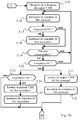
- the Fig. 4 schematically illustrates an algorithm implemented by the 1.3 data flow selection module.
- the module 1.3 receives several streams TS, each encapsulating T2MI packets.
- the module 1.3 performs a compliance analysis of the TS streams received, as already described in relation to the Fig. 3 .
- the module 1.3 extracts T2MI packet streams from the received TS streams.
- the module 1.3 performs a conformity analysis of the extracted T2MI flows, as already described in connection with the Fig. 3 .
- the module 1.3 stores each stream of T2MI packets in a buffer memory.
- Each T2MI packet is stored together with the associated continuity counter value, with an indication of the T2MI packet type, as well as any errors detected in steps 4.2 and 4.4.
- Each T2MI packet is furthermore jointly stored with information representative of the time at which it is stored in the buffer concerned.
- a subsequent step 4.6 the module 1.3 performs a stored T2MI packets flow alignment, and in a subsequent step 4.7, selects a stream from the stored T2MI packets based on the result of the alignment performed and any errors detected. during steps 4.2 and 4.4.
- steps 4.2 and 4.4 One embodiment of these operations is more fully detailed below in relation to the Figs. 5a , 5b and 5c .
- the module 1.3 encapsulates T2MI packets of the stream selected in step 4.7 so as to obtain a stream TS. This stream TS is then transmitted to the modulator 1.4.
- the module 1.3 selects a flow of T2MI packets whose data are not tainted by errors, whether they are errors at the level TS or at the level T2MI. If the flow selected until then becomes tainted with errors, the module 1.3 switches to another stream, aligned, and which is not tainted by errors. Since the streams are aligned at the T2MI level, the switchover does not affect the behavior of the modulator 1.4, which therefore does not need to resynchronize.
- the Figs. 5a , 5b and 5c schematically illustrate an algorithm implemented by the module 1.3 and intended to enable it to determine, among the flow of stored T2MI packets, which are able to be transmitted to the modulator 1.4, and to enable it to align stored T2MI packet streams and select T2MI packets to be encapsulated for transmission to modulator 1.4.
- This algorithm is, in the context of the embodiment described in connection with the Fig. 2 , more particularly implemented by module 2.7.
- Figs. 5a , 5b and 5c The algorithm of Figs. 5a , 5b and 5c is detailed to handle two flows of T2MI packets, but its principle can extend to more flows.
- the algorithm starts, in a step 5.1, by an initialization phase.
- the module 1.3 determines whether data are available in the buffers in which the T2MI packets are to be stored. If this is the case, a step 5.3 is performed, otherwise step 5.2 is repeated.
- the module 1.3 starts a timer. This delay is of a predefined duration, sufficient to compensate for jitter in each of the TS streams received in step 4.1 and to compensate for the possible time shift of transmission between links 1.8 and 1.9.
- step 5.3 the module 1.3 waits for the expiration of the delay corresponding to this delay.
- the module 1.3 selects a stream of T2MI packets stored in step 4.5 as the main stream, that is to say the one which a priori is intended to be encapsulated for transmission to the modulator 1.4. The other stream is then selected as the secondary stream.
- the module 1.3 initializes a counter, associated with the main stream, with a value corresponding to the time when the first T2MI packet of the main stream has been stored in the buffer concerned.
- the module 1.3 terminates the initialization phase and starts a T2MI packet reading phase.
- the module 1.3 determines whether the main flow is tainted with errors, whether at the TS level or at the T2MI level. If this is the case, the module 1.3 considers that the main flow is not able to be transmitted to the modulator 1.4 and a step 5.26 is performed (connection of the flowchart to the label B of the Fig. 5c ); otherwise, a step 5.8 is performed.
- step 5.8 the module 1.3 determines whether the secondary stream is considered aligned. It should be noted that, as a step 5.10 described below is not performed, the secondary stream is not considered aligned. If this is the case, a step 5.11 is performed; otherwise, a step 5.9 is performed.
- step 5.9 module 1.3 determines whether the conditions for the secondary stream to be considered aligned with the main stream are met, that is, if the next T2MI packet to be read for secondary stream is of the same type and has the same continuity counter value as the next T2MI packet for the main stream. If this is the case, a step 5.10 is performed, in which the module 1.3 considers that the secondary stream is aligned, and a step 5.12 is performed; otherwise, a step 5.15 is performed (connection of the flowchart to the label C of the Fig. 5b ).
- step 5.11 the module 1.3 checks whether the conditions for the secondary stream to be considered aligned with the main stream are still met. If this is the case, step 5.12 is performed; otherwise a step 5.14 is performed.
- step 5.12 the module 1.3 determines whether the secondary flow is tainted with errors, whether at the TS level or at the T2MI level. If this is the case, the module 1.3 considers that the secondary stream is not able to be transmitted to the modulator 1.4 and step 5.14 is performed; otherwise, a step 5.13 is performed.
- step 5.13 the module 1.3 updates a counter associated with the secondary stream by giving it a value corresponding to the instant at which the next T2MI packet of the secondary stream has been stored in the buffer concerned.
- step 5.15 is performed (connection of the flowchart to the label C of the Fig. 5b ).
- step 5.14 the memory for T2MI packets of the secondary stream is reset, either because the secondary stream is no longer aligned, or because it contains, or the TS stream that encapsulated it contained, data Wrong.
- step 5.15 is performed (connection of the flowchart to the label C of the Fig. 5b ).
- step 5.15 the module 1.3 gets the length of the T2MI packet to read. This value is common to all the streams capable of being transmitted to the modulator 1.4, since these are aligned.
- step 5.16 the counter associated with the main stream is incremented. This counter is incremented on the basis of the clock rate that was used as a reference to determine the times at which T2MI packets are stored in the buffer. It is considered in the algorithm of Figs. 5a , 5b and 5c that the steps between the steps 5.6 and 5.15 are performed in one stroke of this clock.
- step 5.17 the module 1.3 determines whether the secondary stream is considered aligned. If this is the case, a step 5.18 is performed; otherwise, a step 5.19 is performed.
- step 5.18 the counter associated with the secondary stream is incremented, in the same manner as is associated with the main stream in step 5.16.
- step 5.19 implemented in the context of the embodiment described in relation to the Fig. 2 , the module 1.3 determines whether the encapsulation module 2.8 TS is ready to receive data. If this is the case, a step 5.20 is performed; otherwise, step 5.16 is again implemented.
- a step 5.20 the module 1.3 determines whether the counter associated with the main stream has reached or exceeded a value corresponding to the time at which the next T2MI packet to be read for the main stream has been stored in the buffer. If this is the case, steps 5.21 and 5.23 are performed; otherwise, step 5.16 is again implemented.
- step 5.23 the module 1.3 determines whether the secondary stream is considered aligned. If this is the case, a step 5.24 is performed; otherwise, step 5.6 is repeated (connection of the flowchart to the label D of the Fig. 5a ).
- step 5.24 the T2MI packet of the secondary stream is read at the same rate as is the T2MI packet of the main stream in step 5.21, but is not encapsulated or transmitted for encapsulation. In other words, this package is deleted.
- step 5.25 the counter associated with the secondary flow is incremented, in the same way as it is in step 5.18. Then, step 5.6 is repeated (connection of the flowchart to the label D of the Fig. 5a ).
- step 5.21 the T2MI packet of the main stream is read, and is encapsulated or transmitted for encapsulation. It is therefore selected for encapsulation for transmission to modulator 1.4.
- step 5.22 the counter associated with the main stream is incremented, in the same way as it is in step 5.16. Then, step 5.6 is repeated (connection of the flowchart to the label D of the Fig. 5a ), and a new T2MI packet read phase is implemented.
- steps 5.21 and 5.24 the reading of a T2MI packet is then activated to read a packet of another T2MI stream that the main stream, that is to say the one currently selected, if they are aligned.
- a fixed processing delay is applied by the module 1.3 on the TS streams.
- the TS flow generated by the module 1.3 is slaved to the selected T2MI packet stream.
- step 5.26 the module 1.3 determines whether the secondary stream is considered to be aligned with the main stream, that is to say if step 5.10 was previously performed. If this is the case a step 5.28 is performed; otherwise a step 5.27 is performed.
- step 5.28 module 1.3 determines whether the secondary stream is tainted errors, whether at the TS level or at the T2MI level. If this is the case, the module 1.3 considers that the secondary stream is not able to be transmitted to modulator 1.4 and step 5.27 is performed; otherwise, a step 5.29 is performed.
- step 5.27 the main stream and the secondary stream being faulty, the memories in which the T2MI packets are stored are reset, and step 5.2 is reiterated (connection of the flow chart to the label A of the Fig. 5a ). A new initialization phase is then implemented.
- step 5.29 the main stream being faulty, the buffer in which its T2MI packets are stored is reset, and in a subsequent step 5.30, a flow switchover is performed.
- the secondary stream then becomes the main stream and the main stream becomes the secondary stream.
- step 5.15 is performed (connection of the flowchart to the label C of the Fig. 5b ).
- the T2MI streams are classified according to an order of priority, for example depending on a respective level of robustness of their transmission up to module 1.3.
- the highest priority flow is selected in step 4.7. This makes it possible to reinforce the reliability of the transmission up to the modulator 1.4, by limiting the risk that the selected stream contains errors, visible at the reception of the service, but which do not lead to flow failover within the module. 1.3.
Landscapes
- Engineering & Computer Science (AREA)
- Multimedia (AREA)
- Signal Processing (AREA)
- Computer Networks & Wireless Communication (AREA)
- Two-Way Televisions, Distribution Of Moving Picture Or The Like (AREA)
Claims (11)
- Vorrichtung (1.3), die dazu bestimmt ist, vorgelagert vor einem Modulator (1.4) in einer Ausstrahlungskette von digitalen Dienstströmen angeordnet zu werden, wobei die Vorrichtung Mittel zum Empfangen (1.8; 1.9) von mehreren Transportströmen, die mit dem MPEG-2 TS Standard kompatibel sind, und Mittel zum Übertragen (1.10) eines mit dem MPEG-2 TS Standard kompatiblen Transportstroms an den Modulator aufweist, wobei jeder Transportstrom einen digitalen Dienststrom einkapselt, der geeignet ist, von dem Modulator ausgestrahlt zu werden, wobei die digitalen Dienstflüsse für einen gleichen digitalen Dienst repräsentativ sind und sogenannte T2MI-Frames von identischer Form und Größe im Rahmen des DVB-T2-Standards aufweisen, dadurch gekennzeichnet, dass sie aufweist:- Mittel zum Extrahieren (2.3; 2.4) von digitalen Dienstströmen aus den empfangenen Transportströmen;- Mittel zum Erfassen (2.1; 2.22.3; 2.4) eines Fehlers an den empfangenen Transportströmen und an den extrahierten digitalen Dienstströmen;- Mittel zum Ausrichten (2.5; 2.6; 2.7) von extrahierten digitalen Dienstströmen;- Mittel zum Auswählen (2.7) eines Stroms unter den ausgerichteten digitalen Dienstströmen in Abhängigkeit von eventuellen Fehlern, die durch die Mittel zum Erfassen erfasst werden;- Mittel zum Einkapseln (2.8) des ausgewählten digitalen Dienststroms, um den Transportstrom zu bilden, der an den Modulator zu übertragen ist.
- Vorrichtung nach Anspruch 1, dadurch gekennzeichnet, dass die Mittel zum Ausrichten Mittel zum Speichern (2.5; 2.6) der Pakete der extrahierten digitalen Dienstströme in Übereinstimmung mit jeweiligen Informationen der Art des Pakets und jeweiligen Werten eines Kontinuitätszählers der Pakete in ihren jeweiligen digitalen Dienstströmen aufweisen.
- Vorrichtung nach Anspruch 2, dadurch gekennzeichnet, dass die Mittel zum Ausrichten Mittel zum Lesen des gespeicherten Pakets aufweisen, und dadurch, dass, nachdem die Mittel eingesetzt werden, um ein Paket eines bestimmten digitalen Dienststroms zu lesen, die Mittel ferner aktiviert werden, um ein Paket eines anderen digitalen Dienststroms zu lesen, wenn ihre jeweiligen Informationen der Art des Pakets und ihrer jeweiligen Werte eines Kontinuitätszählers übereinstimmen.
- Vorrichtung nach Anspruch 3, dadurch gekennzeichnet, dass die Mittel zum Speichern geeignet sind, um die Pakete der extrahierten digitalen Dienstströme in Übereinstimmung mit jeweiligen Informationen, die für Augenblicke repräsentativ sind, an denen die Pakete jeweils gespeichert werden, zu speichern, und dadurch, dass die Mittel zum Lesen ferner in Abhängigkeit von den Informationen aktiviert werden.
- Vorrichtung nach einem der Ansprüche 2 bis 4, dadurch gekennzeichnet, dass die Mittel zum Lesen anfänglich infolge des Ablaufs einer Verzögerungszeit von vorbestimmter Dauer, die bei dem Speichern des ersten Pakets des Stroms gestartet wird, aktiviert werden.
- Vorrichtung nach einem der Ansprüche 1 bis 5, dadurch gekennzeichnet, dass die Mittel zum Auswählen ein vorbestimmte Rangfolge zwischen den ausgerichteten digitalen Dienstströmen berücksichtigen.
- System (1.1, 1.2, 1.3) zum Ausstrahlen von digitalen Dienstströmen, wobei das System dazu bestimmt ist, an einen Modulator (1.4) einen Transportstrom zu übertragen, der einen digitalen Dienststrom einkapselt, der geeignet ist, durch den Modulator ausgestrahlt zu werden, dadurch gekennzeichnet, dass es eine Vorrichtung (1.3) nach einem der Ansprüche 1 bis 5 aufweist, wobei die Vorrichtung zum Auswählen von Strömen und mindestens eine Provider-Vorrichtung (1.1; 1.2) der Vorrichtung zum Auswählen von Strömen mehrere Transportströme bereitstellen.
- System nach Anspruch 7, dadurch gekennzeichnet, dass es mehrere Provider-Vorrichtungen aufweist und dadurch, dass die Provider-Vorrichtungen aufweisen:- Mittel zum Zuweisen eines Master-Status zu einer bestimmten Provider-Vorrichtung, wobei jeder anderen Provider-Vorrichtung ein Slave-Status zugewiesen wird;- jeweilige Mittel zum Generieren von digitalen Dienstströmen, wobei die Mittel zum Generieren von jeder Slave-Vorrichtung vorrübergehend jenen der Master-Vorrichtung unterworfen sind.
- Verfahren, das von einer Vorrichtung (1.3) umgesetzt wird, die dazu bestimmt ist, vorgelagert vor einem Modulator (1.4) in einer Ausstrahlungskette von digitalen Dienstströmen angeordnet zu werden, wobei die Vorrichtung Mittel zum Empfangen (1.8; 1.9) von mehreren von Transportströmen, die mit dem MPEG-2 TS Standard kompatibel sind, und Mittel zum Übertragen (1.10) eines mit dem MPEG-2 TS Standard kompatiblen Transportstroms an den Modulator aufweist, wobei jeder Transportstrom einen digitalen Dienststrom einkapselt, der geeignet ist, von dem Modulator ausgestrahlt zu werden, wobei die digitalen Dienstströme für einen gleichen digitalen Dienst repräsentativ sind und sogenannte T2MI-Frames von identischer Form und Größe im Rahmen des DVB-T2-Standards aufweisen, dadurch gekennzeichnet, dass es Schritte aufweist:- des Extrahierens (4.3) von digitalen Dienstströmen aus den von der Vorrichtung empfangenen Transportströmen;- des Erfassens (4.2; 4.4) eines Fehlers an den empfangenen Transportströmen und an den extrahierten digitalen Dienstströmen;- des Ausrichtens (4.6) von extrahierten digitalen Dienstströmen;- des Auswählens (4.7) eines Stroms unter den ausgerichteten digitalen Dienstströmen in Abhängigkeit von eventuellen Fehlern, die durch die Mittel zum Erfassen erfasst sind;- des Einkapselns (4.8) des ausgewählten digitalen Dienststroms, um den Transportstrom zu bilden, der an den Modulator zu übertragen ist.
- Computerprogramm, dadurch gekennzeichnet, dass es Anweisungen zum Umsetzen durch eine Vorrichtung, die dazu bestimmt ist, vorgelagert vor einem Modulator in einer Ausstrahlungskette von digitalen Dienstströmen angeordnet zu werden, des Verfahrens nach Anspruch 9 aufweist, wenn das Programm von einem Prozessor der Vorrichtung ausgeführt wird.
- Mittel zum Speichern, dadurch gekennzeichnet, dass sie ein Computerprogramm speichern, das Anweisungen zum Umsetzen durch eine Vorrichtung, die dazu bestimmt ist, vorgelagert vor einem Modulator in einer Ausstrahlungskette von digitalen Dienstströmen angeordnet zu werden, des Verfahrens nach Anspruch 9 aufweist, wenn das Programm von einem Prozessor der Vorrichtung ausgeführt wird.
Applications Claiming Priority (2)
| Application Number | Priority Date | Filing Date | Title |
|---|---|---|---|
| FR1060266A FR2968791B1 (fr) | 2010-12-08 | 2010-12-08 | Dispositif de selection de flux de service numerique, et procede, programme d'ordinateur et moyens de stockage correspondants |
| PCT/EP2011/071838 WO2012076490A1 (fr) | 2010-12-08 | 2011-12-06 | Dispositif de sélection de flux de service numérique, et procédé, programme d'ordinateur et moyens de stockage correspondants |
Publications (2)
| Publication Number | Publication Date |
|---|---|
| EP2649738A1 EP2649738A1 (de) | 2013-10-16 |
| EP2649738B1 true EP2649738B1 (de) | 2018-08-15 |
Family
ID=44201858
Family Applications (1)
| Application Number | Title | Priority Date | Filing Date |
|---|---|---|---|
| EP11791554.6A Active EP2649738B1 (de) | 2010-12-08 | 2011-12-06 | Vorrichtung zur stream-auswahl bei digitalen diensten sowie verfahren, computerprogramm und speichervorrichtung dafür |
Country Status (5)
| Country | Link |
|---|---|
| US (1) | US9049270B2 (de) |
| EP (1) | EP2649738B1 (de) |
| ES (1) | ES2696545T3 (de) |
| FR (1) | FR2968791B1 (de) |
| WO (1) | WO2012076490A1 (de) |
Families Citing this family (11)
| Publication number | Priority date | Publication date | Assignee | Title |
|---|---|---|---|---|
| FR2999853B1 (fr) * | 2012-12-13 | 2018-05-25 | Enensys Technologies | Procede de generation et de transfert d'au moins un flux de donnees |
| US9706509B2 (en) * | 2013-12-05 | 2017-07-11 | Cisco Technology, Inc. | Synchronization of streaming data |
| FR3015739B1 (fr) * | 2013-12-19 | 2017-05-26 | Enensys Tech | Procede de generation d’un marquage temporel pour une diffusion terrestre synchrone |
| US10129839B2 (en) * | 2014-12-05 | 2018-11-13 | Qualcomm Incorporated | Techniques for synchronizing timing of wireless streaming transmissions to multiple sink devices |
| DE102015001622A1 (de) | 2015-02-09 | 2016-08-11 | Unify Gmbh & Co. Kg | Verfahren zur Übertragung von Daten in einem Multimedia-System, sowie Softwareprodukt und Vorrichtung zur Steuerung der Übertragung von Daten in einem Multimedia-System |
| CN107567689B (zh) * | 2015-05-14 | 2019-12-13 | 瑞典爱立信有限公司 | 用于在无线网络中同步节点的方法和系统 |
| US9843837B2 (en) * | 2015-08-03 | 2017-12-12 | At&T Intellectual Property I, L.P. | Cross-platform analysis |
| EP3148103B1 (de) | 2015-09-28 | 2022-04-20 | Nxp B.V. | Audiodatenverarbeitung |
| RU2621063C1 (ru) * | 2016-06-14 | 2017-05-31 | ТимКаст Текнолоджи | Сообщение для передачи данных, способ передачи множества указанных сообщений, способ регионализации контента (варианты) и способ регионализации сигнализации регионального букета |
| RU2649415C1 (ru) * | 2017-04-10 | 2018-04-03 | Владимир Леонидович Карякин | Региональная сеть цифрового тв вещания стандарта dvb-t2 |
| FR3068559B1 (fr) * | 2017-06-30 | 2019-08-02 | Enensys Technologies | Procede de generation d'un flux de donnees, passerelle de diffusion, procede et equipement de selection d'un flux de donnees et programme d'ordinateur correspondant |
Family Cites Families (5)
| Publication number | Priority date | Publication date | Assignee | Title |
|---|---|---|---|---|
| GB9921209D0 (en) * | 1999-09-08 | 1999-11-10 | British Telecomm | Signal switching |
| US6839865B2 (en) * | 2000-12-29 | 2005-01-04 | Road Runner | System and method for multicast stream failover |
| US7796598B2 (en) * | 2006-04-03 | 2010-09-14 | Cisco Technology, Inc. | Synchronizing redundant video streams encapsulated in IP/UDP packets |
| FR2928513B1 (fr) | 2008-03-07 | 2011-02-11 | Enensys Technologies | Procede de synchronisation d'une pluralite de modules de formatage |
| FR2936919B1 (fr) * | 2008-10-06 | 2013-01-11 | Enensys Technologies | Dispositif et procede de synchronisation fine de differentes versions d'un flux de donnees recues |
-
2010
- 2010-12-08 FR FR1060266A patent/FR2968791B1/fr active Active
-
2011
- 2011-12-06 WO PCT/EP2011/071838 patent/WO2012076490A1/fr not_active Ceased
- 2011-12-06 EP EP11791554.6A patent/EP2649738B1/de active Active
- 2011-12-06 ES ES11791554T patent/ES2696545T3/es active Active
- 2011-12-06 US US13/992,276 patent/US9049270B2/en active Active
Non-Patent Citations (1)
| Title |
|---|
| None * |
Also Published As
| Publication number | Publication date |
|---|---|
| ES2696545T3 (es) | 2019-01-16 |
| FR2968791A1 (fr) | 2012-06-15 |
| FR2968791B1 (fr) | 2013-01-11 |
| US9049270B2 (en) | 2015-06-02 |
| EP2649738A1 (de) | 2013-10-16 |
| US20130322557A1 (en) | 2013-12-05 |
| WO2012076490A1 (fr) | 2012-06-14 |
Similar Documents
| Publication | Publication Date | Title |
|---|---|---|
| EP2649738B1 (de) | Vorrichtung zur stream-auswahl bei digitalen diensten sowie verfahren, computerprogramm und speichervorrichtung dafür | |
| CA2390699C (fr) | Surveillance de la qualite de service dans une liaison de television numerique | |
| AU2013330649A2 (en) | Method and apparatus for media data delivery control | |
| EP2709369B1 (de) | Vorrichtung für DVB-T2-Diffusion mit Einfügung eines regionalen Inhalts in T2-MI Format | |
| FR2892253A1 (fr) | Procede de generation et de demultiplexage d'un signal de contribution optimise, et systeme de diffusion regionalisee de donnees. | |
| EP2215845A2 (de) | Optimiertes verfahren zur übertragung geschichteter inhalte an mobile endgeräte über eine funkinfrastruktur mit tdm/tdma/ofdma-zugangsverfahren sowie verarbeitungsvorrichtung dafür | |
| WO2014090928A1 (fr) | Procédé de génération et de transfert d'au moins un flux de données | |
| FR2880749A1 (fr) | Methode de transmission de flux mpeg sur ip et appareil implementant la methode | |
| WO2016166214A1 (fr) | Procédé de remplacement d'un contenu principal par au moins un contenu secondaire, équipement de remplacement de contenus et programme d'ordinateur correspondants | |
| EP2345185A1 (de) | Vorrichtung und verfahren zur feinsynchronisation verschiedener versionen eines empfangenen datenstroms | |
| WO2019002224A1 (fr) | Procédé de génération d'un flux de données, passerelle de diffusion, procédé et équipement de sélection d'un flux de données et programme d'ordinateur correspondant | |
| EP0781480B1 (de) | Vorrichtung zur leitweglenkung von paketen | |
| FR2932037A1 (fr) | Dispositif et procede de synchronisation de flux de donnees numeriques. | |
| EP3643072A1 (de) | Verfahren und vorrichtung zur erzeugung eines transportstroms, rundfunkverfahren und -stelle und computerprogramm dafür | |
| FR2907297A1 (fr) | Procede de notification d'urgence dans un systeme de diffusion de services numeriques, dispositif emetteur et dispositif de reception mettant en oeuvre le procede | |
| EP2277313A1 (de) | Verfahren zum synchronisieren mehrerer formatierungsmodule | |
| WO2016193269A1 (fr) | Procede de traitement d'un flux global d'origine comprenant au moins un tunnel couche physique encapsulant un flux de transport | |
| FR3091109A1 (fr) | Procédé et équipement de génération d’un flux de transport destiné à être distribué à une pluralité de sites de diffusion, procédé et site de diffusion de données, et programme d’ordinateur correspondants. | |
| FR2891973A1 (fr) | Procede et dispositif de changement de groupes de datagrammes achemines par des paquets d'un flux de transport recu par un dispositif de reception radiofrequence | |
| FR3032077A1 (fr) | Procede de diffusion multipoint d'un flux de donnees au format ip | |
| WO2016016403A1 (fr) | Procédé de diffusion d'un service d'alerte | |
| FR2726722A1 (fr) | Procede de deroutage de paquets destines a etre mis en oeuvre dans une unite de reception d'un systeme de transmission de donnees numeriques arrangees en paquets | |
| EP2087733A1 (de) | Verfahren zur zeitverzögerung eines flusses digitaler inhalte und diesbezügliche einrichtung und computersoftwareprodukt |
Legal Events
| Date | Code | Title | Description |
|---|---|---|---|
| PUAI | Public reference made under article 153(3) epc to a published international application that has entered the european phase |
Free format text: ORIGINAL CODE: 0009012 |
|
| 17P | Request for examination filed |
Effective date: 20130702 |
|
| AK | Designated contracting states |
Kind code of ref document: A1 Designated state(s): AL AT BE BG CH CY CZ DE DK EE ES FI FR GB GR HR HU IE IS IT LI LT LU LV MC MK MT NL NO PL PT RO RS SE SI SK SM TR |
|
| DAX | Request for extension of the european patent (deleted) | ||
| 17Q | First examination report despatched |
Effective date: 20150428 |
|
| GRAP | Despatch of communication of intention to grant a patent |
Free format text: ORIGINAL CODE: EPIDOSNIGR1 |
|
| INTG | Intention to grant announced |
Effective date: 20180312 |
|
| GRAS | Grant fee paid |
Free format text: ORIGINAL CODE: EPIDOSNIGR3 |
|
| GRAA | (expected) grant |
Free format text: ORIGINAL CODE: 0009210 |
|
| AK | Designated contracting states |
Kind code of ref document: B1 Designated state(s): AL AT BE BG CH CY CZ DE DK EE ES FI FR GB GR HR HU IE IS IT LI LT LU LV MC MK MT NL NO PL PT RO RS SE SI SK SM TR |
|
| REG | Reference to a national code |
Ref country code: CH Ref legal event code: EP Ref country code: GB Ref legal event code: FG4D Free format text: NOT ENGLISH Ref country code: AT Ref legal event code: REF Ref document number: 1030990 Country of ref document: AT Kind code of ref document: T Effective date: 20180815 |
|
| REG | Reference to a national code |
Ref country code: IE Ref legal event code: FG4D Free format text: LANGUAGE OF EP DOCUMENT: FRENCH |
|
| REG | Reference to a national code |
Ref country code: DE Ref legal event code: R096 Ref document number: 602011051125 Country of ref document: DE |
|
| REG | Reference to a national code |
Ref country code: NL Ref legal event code: MP Effective date: 20180815 |
|
| REG | Reference to a national code |
Ref country code: LT Ref legal event code: MG4D |
|
| REG | Reference to a national code |
Ref country code: AT Ref legal event code: MK05 Ref document number: 1030990 Country of ref document: AT Kind code of ref document: T Effective date: 20180815 |
|
| REG | Reference to a national code |
Ref country code: ES Ref legal event code: FG2A Ref document number: 2696545 Country of ref document: ES Kind code of ref document: T3 Effective date: 20190116 |
|
| REG | Reference to a national code |
Ref country code: NO Ref legal event code: T2 Effective date: 20180815 |
|
| PG25 | Lapsed in a contracting state [announced via postgrant information from national office to epo] |
Ref country code: BG Free format text: LAPSE BECAUSE OF FAILURE TO SUBMIT A TRANSLATION OF THE DESCRIPTION OR TO PAY THE FEE WITHIN THE PRESCRIBED TIME-LIMIT Effective date: 20181115 Ref country code: SE Free format text: LAPSE BECAUSE OF FAILURE TO SUBMIT A TRANSLATION OF THE DESCRIPTION OR TO PAY THE FEE WITHIN THE PRESCRIBED TIME-LIMIT Effective date: 20180815 Ref country code: NL Free format text: LAPSE BECAUSE OF FAILURE TO SUBMIT A TRANSLATION OF THE DESCRIPTION OR TO PAY THE FEE WITHIN THE PRESCRIBED TIME-LIMIT Effective date: 20180815 Ref country code: LT Free format text: LAPSE BECAUSE OF FAILURE TO SUBMIT A TRANSLATION OF THE DESCRIPTION OR TO PAY THE FEE WITHIN THE PRESCRIBED TIME-LIMIT Effective date: 20180815 Ref country code: FI Free format text: LAPSE BECAUSE OF FAILURE TO SUBMIT A TRANSLATION OF THE DESCRIPTION OR TO PAY THE FEE WITHIN THE PRESCRIBED TIME-LIMIT Effective date: 20180815 Ref country code: AT Free format text: LAPSE BECAUSE OF FAILURE TO SUBMIT A TRANSLATION OF THE DESCRIPTION OR TO PAY THE FEE WITHIN THE PRESCRIBED TIME-LIMIT Effective date: 20180815 Ref country code: RS Free format text: LAPSE BECAUSE OF FAILURE TO SUBMIT A TRANSLATION OF THE DESCRIPTION OR TO PAY THE FEE WITHIN THE PRESCRIBED TIME-LIMIT Effective date: 20180815 Ref country code: GR Free format text: LAPSE BECAUSE OF FAILURE TO SUBMIT A TRANSLATION OF THE DESCRIPTION OR TO PAY THE FEE WITHIN THE PRESCRIBED TIME-LIMIT Effective date: 20181116 Ref country code: IS Free format text: LAPSE BECAUSE OF FAILURE TO SUBMIT A TRANSLATION OF THE DESCRIPTION OR TO PAY THE FEE WITHIN THE PRESCRIBED TIME-LIMIT Effective date: 20181215 |
|
| PG25 | Lapsed in a contracting state [announced via postgrant information from national office to epo] |
Ref country code: AL Free format text: LAPSE BECAUSE OF FAILURE TO SUBMIT A TRANSLATION OF THE DESCRIPTION OR TO PAY THE FEE WITHIN THE PRESCRIBED TIME-LIMIT Effective date: 20180815 Ref country code: HR Free format text: LAPSE BECAUSE OF FAILURE TO SUBMIT A TRANSLATION OF THE DESCRIPTION OR TO PAY THE FEE WITHIN THE PRESCRIBED TIME-LIMIT Effective date: 20180815 Ref country code: LV Free format text: LAPSE BECAUSE OF FAILURE TO SUBMIT A TRANSLATION OF THE DESCRIPTION OR TO PAY THE FEE WITHIN THE PRESCRIBED TIME-LIMIT Effective date: 20180815 |
|
| PG25 | Lapsed in a contracting state [announced via postgrant information from national office to epo] |
Ref country code: PL Free format text: LAPSE BECAUSE OF FAILURE TO SUBMIT A TRANSLATION OF THE DESCRIPTION OR TO PAY THE FEE WITHIN THE PRESCRIBED TIME-LIMIT Effective date: 20180815 Ref country code: EE Free format text: LAPSE BECAUSE OF FAILURE TO SUBMIT A TRANSLATION OF THE DESCRIPTION OR TO PAY THE FEE WITHIN THE PRESCRIBED TIME-LIMIT Effective date: 20180815 Ref country code: RO Free format text: LAPSE BECAUSE OF FAILURE TO SUBMIT A TRANSLATION OF THE DESCRIPTION OR TO PAY THE FEE WITHIN THE PRESCRIBED TIME-LIMIT Effective date: 20180815 Ref country code: CZ Free format text: LAPSE BECAUSE OF FAILURE TO SUBMIT A TRANSLATION OF THE DESCRIPTION OR TO PAY THE FEE WITHIN THE PRESCRIBED TIME-LIMIT Effective date: 20180815 |
|
| REG | Reference to a national code |
Ref country code: DE Ref legal event code: R097 Ref document number: 602011051125 Country of ref document: DE |
|
| PG25 | Lapsed in a contracting state [announced via postgrant information from national office to epo] |
Ref country code: SK Free format text: LAPSE BECAUSE OF FAILURE TO SUBMIT A TRANSLATION OF THE DESCRIPTION OR TO PAY THE FEE WITHIN THE PRESCRIBED TIME-LIMIT Effective date: 20180815 Ref country code: DK Free format text: LAPSE BECAUSE OF FAILURE TO SUBMIT A TRANSLATION OF THE DESCRIPTION OR TO PAY THE FEE WITHIN THE PRESCRIBED TIME-LIMIT Effective date: 20180815 Ref country code: SM Free format text: LAPSE BECAUSE OF FAILURE TO SUBMIT A TRANSLATION OF THE DESCRIPTION OR TO PAY THE FEE WITHIN THE PRESCRIBED TIME-LIMIT Effective date: 20180815 |
|
| PLBE | No opposition filed within time limit |
Free format text: ORIGINAL CODE: 0009261 |
|
| STAA | Information on the status of an ep patent application or granted ep patent |
Free format text: STATUS: NO OPPOSITION FILED WITHIN TIME LIMIT |
|
| 26N | No opposition filed |
Effective date: 20190516 |
|
| REG | Reference to a national code |
Ref country code: CH Ref legal event code: PL |
|
| PG25 | Lapsed in a contracting state [announced via postgrant information from national office to epo] |
Ref country code: MC Free format text: LAPSE BECAUSE OF FAILURE TO SUBMIT A TRANSLATION OF THE DESCRIPTION OR TO PAY THE FEE WITHIN THE PRESCRIBED TIME-LIMIT Effective date: 20180815 Ref country code: SI Free format text: LAPSE BECAUSE OF FAILURE TO SUBMIT A TRANSLATION OF THE DESCRIPTION OR TO PAY THE FEE WITHIN THE PRESCRIBED TIME-LIMIT Effective date: 20180815 Ref country code: LU Free format text: LAPSE BECAUSE OF NON-PAYMENT OF DUE FEES Effective date: 20181206 |
|
| REG | Reference to a national code |
Ref country code: IE Ref legal event code: MM4A |
|
| REG | Reference to a national code |
Ref country code: BE Ref legal event code: MM Effective date: 20181231 |
|
| PG25 | Lapsed in a contracting state [announced via postgrant information from national office to epo] |
Ref country code: IE Free format text: LAPSE BECAUSE OF NON-PAYMENT OF DUE FEES Effective date: 20181206 |
|
| PG25 | Lapsed in a contracting state [announced via postgrant information from national office to epo] |
Ref country code: BE Free format text: LAPSE BECAUSE OF NON-PAYMENT OF DUE FEES Effective date: 20181231 |
|
| PG25 | Lapsed in a contracting state [announced via postgrant information from national office to epo] |
Ref country code: LI Free format text: LAPSE BECAUSE OF NON-PAYMENT OF DUE FEES Effective date: 20181231 Ref country code: CH Free format text: LAPSE BECAUSE OF NON-PAYMENT OF DUE FEES Effective date: 20181231 |
|
| PG25 | Lapsed in a contracting state [announced via postgrant information from national office to epo] |
Ref country code: MT Free format text: LAPSE BECAUSE OF FAILURE TO SUBMIT A TRANSLATION OF THE DESCRIPTION OR TO PAY THE FEE WITHIN THE PRESCRIBED TIME-LIMIT Effective date: 20180815 |
|
| PG25 | Lapsed in a contracting state [announced via postgrant information from national office to epo] |
Ref country code: TR Free format text: LAPSE BECAUSE OF FAILURE TO SUBMIT A TRANSLATION OF THE DESCRIPTION OR TO PAY THE FEE WITHIN THE PRESCRIBED TIME-LIMIT Effective date: 20180815 |
|
| PGFP | Annual fee paid to national office [announced via postgrant information from national office to epo] |
Ref country code: GB Payment date: 20191220 Year of fee payment: 9 |
|
| PG25 | Lapsed in a contracting state [announced via postgrant information from national office to epo] |
Ref country code: PT Free format text: LAPSE BECAUSE OF FAILURE TO SUBMIT A TRANSLATION OF THE DESCRIPTION OR TO PAY THE FEE WITHIN THE PRESCRIBED TIME-LIMIT Effective date: 20180815 |
|
| PG25 | Lapsed in a contracting state [announced via postgrant information from national office to epo] |
Ref country code: CY Free format text: LAPSE BECAUSE OF FAILURE TO SUBMIT A TRANSLATION OF THE DESCRIPTION OR TO PAY THE FEE WITHIN THE PRESCRIBED TIME-LIMIT Effective date: 20180815 Ref country code: MK Free format text: LAPSE BECAUSE OF NON-PAYMENT OF DUE FEES Effective date: 20180815 Ref country code: HU Free format text: LAPSE BECAUSE OF FAILURE TO SUBMIT A TRANSLATION OF THE DESCRIPTION OR TO PAY THE FEE WITHIN THE PRESCRIBED TIME-LIMIT; INVALID AB INITIO Effective date: 20111206 |
|
| GBPC | Gb: european patent ceased through non-payment of renewal fee |
Effective date: 20201206 |
|
| PG25 | Lapsed in a contracting state [announced via postgrant information from national office to epo] |
Ref country code: GB Free format text: LAPSE BECAUSE OF NON-PAYMENT OF DUE FEES Effective date: 20201206 |
|
| PGFP | Annual fee paid to national office [announced via postgrant information from national office to epo] |
Ref country code: DE Payment date: 20251126 Year of fee payment: 15 |
|
| PGFP | Annual fee paid to national office [announced via postgrant information from national office to epo] |
Ref country code: NO Payment date: 20251121 Year of fee payment: 15 |
|
| PGFP | Annual fee paid to national office [announced via postgrant information from national office to epo] |
Ref country code: IT Payment date: 20251119 Year of fee payment: 15 |
|
| PGFP | Annual fee paid to national office [announced via postgrant information from national office to epo] |
Ref country code: FR Payment date: 20251120 Year of fee payment: 15 |
|
| PGFP | Annual fee paid to national office [announced via postgrant information from national office to epo] |
Ref country code: ES Payment date: 20260102 Year of fee payment: 15 |