EP2649853B1 - Prévision de charge adaptative pour récepteurs de suppression d'interférence - Google Patents
Prévision de charge adaptative pour récepteurs de suppression d'interférence Download PDFInfo
- Publication number
- EP2649853B1 EP2649853B1 EP11846605.1A EP11846605A EP2649853B1 EP 2649853 B1 EP2649853 B1 EP 2649853B1 EP 11846605 A EP11846605 A EP 11846605A EP 2649853 B1 EP2649853 B1 EP 2649853B1
- Authority
- EP
- European Patent Office
- Prior art keywords
- interference suppression
- load
- users
- interference
- computing
- Prior art date
- Legal status (The legal status is an assumption and is not a legal conclusion. Google has not performed a legal analysis and makes no representation as to the accuracy of the status listed.)
- Not-in-force
Links
Images


Classifications
-
- H—ELECTRICITY
- H04—ELECTRIC COMMUNICATION TECHNIQUE
- H04W—WIRELESS COMMUNICATION NETWORKS
- H04W72/00—Local resource management
- H04W72/12—Wireless traffic scheduling
- H04W72/1263—Mapping of traffic onto schedule, e.g. scheduled allocation or multiplexing of flows
- H04W72/1268—Mapping of traffic onto schedule, e.g. scheduled allocation or multiplexing of flows of uplink data flows
-
- H—ELECTRICITY
- H04—ELECTRIC COMMUNICATION TECHNIQUE
- H04W—WIRELESS COMMUNICATION NETWORKS
- H04W72/00—Local resource management
- H04W72/50—Allocation or scheduling criteria for wireless resources
- H04W72/52—Allocation or scheduling criteria for wireless resources based on load
Definitions
- the present invention relates generally to uplink scheduling in a wireless communication network using interference suppression receivers at the base station, and more particularly to load prediction for interference suppression receivers.
- interference suppression In some types of wireless communication systems, such as Wideband Code Division Multiple Access (WCDMA) systems, interference suppression (IS) is used in order to achieve better performance in terms of peak data rates, coverage, system throughput, and system capacity.
- interference suppression receivers include the GRAKE+ receiver, the Frequency Domain Equalization (FDE) receiver, and the Frequency Domain Pre-Equalization (FDPE) receiver.
- the Enhanced Uplink (EUL) in WCDMA employs fast scheduling and a short transmission time interval (TTI) in order to use increase total throughput on the uplink and reduce delay.
- TTI transmission time interval
- the users report channel conditions and buffer status to the base station.
- a scheduler at the base station determines which users are allowed to transmit in a given TTI and at what data rate based on the channel and load conditions. Because the transmissions on the uplink are not orthogonal, the uplink transmissions by each user creates interference for the other users. If the interference level is too high, the base station may not be able to receive some transmissions. On the other hand, if the interference level is too low, the full system capacity will not be exploited.
- the scheduler at the base station estimates the load at the base station due to its scheduling decisions and tries to maintain the total load below a predetermined threshold. Prediction of the uplink load is difficult because of the inherent delay between the time that scheduling decisions are made and the time that the users transmit on the uplink.
- an estimate of the predicted load is based on measurements of the signal-to-interference ratio (SIR) together with beta factors that define the power offset of a user relative to a power-controlled control channel. This technique is suitable for conventional receivers that do not employ interference suppression.
- SIR signal-to-interference ratio
- interference suppression receivers in the near future will make the load prediction problem substantially more difficult for several reasons.
- the conventional load measures based on measurements of the SIR will not reflect the load after interference suppression that is applicable to interference suppression receivers.
- Second, the amount of the load reduction due to interference suppression receivers will vary depending on the number of interfering users in the cell.
- Third, the amount of the load reduction will vary depending on the data rates of the users transmitting on the uplink.
- the present invention encompasses methods and apparatus for load prediction in a wireless communication network employing interference suppression receivers as set out in the appended claims.
- a new load measure having low computational complexity is provided that gives an effective load after interference suppression.
- the effective load after interference is compared with the air interface load to determine interference suppression gains for different user constellations.
- the interference suppression gains may be stored in the form of a gain table that gives the expected interference suppression gains for different user constellations.
- the expected interference suppression gains may be used by a scheduler at a base station to predict the effective load for two or more candidate user constellations, and to select one of the candidate user constellations. Users are then scheduled according to the selected user constellation.
- Exemplary embodiments of the invention comprise methods of scheduling uplink transmissions from a plurality of users to a base station in a communication network.
- the base station estimates interference suppression gains for two or more candidate user constellations, and computes predicted loads for a scheduling interval for each of the two or more candidate user constellations as a function of the estimated interference suppression gains.
- the base station then schedules uplink transmissions from one or more of the users during the scheduling interval based on the predicted loads.
- the base station includes an interference suppression receiver to suppress interference in received signals from a plurality of users, and a control circuit to schedule uplink transmissions from the users.
- the control circuit includes a scheduler configured to estimate interference suppression gains for two or more candidate user constellations, compute predicted loads for a scheduling interval for each of the two or more candidate user constellations as a function of the estimated interference suppression gains for the candidate user constellations, and to schedule uplink transmissions from one or more of the users during the scheduling interval based on the predicted loads.
- Embodiments of the present invention provide a more accurate estimate of the predicted loads when interference suppression receivers are used, and enable the base station to operate with lower margins. As a result, more efficient use of the uplink resources is realized.
- WCDMA Wideband Code Division Multiple Access
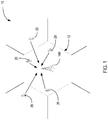
- Figure 1 illustrates a wireless communication network 10 including a base station 100 implementing fast scheduling on the uplink.
- the base station 100 provides service to a plurality of users 20 within a cell 12 served by the base station 100.
- the base station 100 receives signals of interest on an uplink (UL) channel from users 20 within the cell 12 served by the base station 20.
- the base station 100 also receives interfering signals from users 20 in neighboring cells.
- UL uplink
- fast scheduling is used on the uplink.
- Fast scheduling allows the base station 100 to adjust the maximum data rate of the users 20 transmitting on the uplink, and to allocate the uplink resources among the users 20 in response to the uplink traffic demands and interference conditions.
- the network 10 can be operated close to the maximum load; leading to increased data rates for users 20 and increased uplink capacity.
- a load estimator is used to estimate the cell load.
- the total load is the sum of the load due to users 20 within the cell and to users 20 in neighboring cells.
- the load estimator estimates the load as seen by the base station 100 and determines the scheduling headroom (i.e., the difference between the maximum allowed load and the estimated load).
- the scheduling headroom limits the number of users 20 that can simultaneously transmit on the uplink, and also limits the data rates of the users 20.
- a scheduler 150 (see Figure 2 ) at the base station 100 determines how many users 20 to schedule on the uplink, and what data rates to allow for each user 20.
- the cell load is conventionally estimated in terms of the rise over thermal noise ( RoT ) in the cell.
- the base station 100 estimates the expected load due to its scheduling decisions, and tries to maintain the total load below a predetermined threshold.
- W i represents the spreading factor for user i
- RxLoss represents missed receiver energy
- G represents the diversity gain
- the ⁇ 's represent the beta factors of the respective channels (assuming non-active channels have zero beta factors).
- Exemplary embodiments of the present invention provide estimates and predictions of the effective load after interference suppression. Improved accuracy in load estimation and load prediction allows the system to operate closer to its pole capacity. As a result, data rates for users 20 will increase and uplink capacity will be increased.
- exemplary embodiments of the invention provide techniques for determining the interference suppression gains for different "user constellations.”
- the term "user constellation” as used herein refers to a configuration of users 20 resulting from a set of scheduling grants.
- a user constellation is defined by the number of users 20 and corresponding data rates.
- a first user constellation may comprise three users 20 transmitting at data rates of 960 kbit/s, 640 kbit/s, and 640 kbit/s respectively.
- a second user constellation may comprise two users 20 both transmitting at data rates of 960 kbit/s.
- a scheduler 150 at a base station 100 provides a set of candidate user constellations to a load estimation circuit 140.
- the load estimation circuit 140 provides the scheduler 150 with estimates of the predicted air interface load for each of the candidate user constellation (see Figure 2 ).
- the scheduler 150 at the base station 100 computes a predicted "effective load" after interference suppression as a function of the air interface load for each candidate user constellation and the interference suppression gain and selects one of the candidate user constellations.
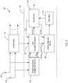
- FIG. 2 illustrates the main functional components in an exemplary base station 100.
- the base station 100 comprises an interference suppression (IS) receiver 110 coupled to one or more antennas 102, and a control circuit 120.
- the signals received by the antennas 102 from the users 20 are input to the interference suppression receiver 110.
- the interference suppression receiver 110 demodulates the received signals and suppresses interference in the received signals.
- the demodulated signals with interference suppressed are output to a decoder (not shown).
- the control circuit 120 is responsible for monitoring the uplink load and scheduling the uplink transmissions from the users 20.
- the control circuit 120 includes a power and noise estimation circuit 130, a load estimation circuit 140, a scheduler 150, a gain estimation circuit 160, and a gain table 170 stored in non-volatile memory.
- the power and noise estimation circuit 130 generate estimates of the total wideband received power P RTWP before interference and thermal noise power P N .
- the thermal noise power P N is estimated from the measured P RIWP . Exemplary techniques for estimating the thermal noise are described in T. Wigren, "Recursive noise floor estimation in WCDMA", IEEE Trans. Veh. Tech., vol. 59, no. 5, pp. 2615-2620, 2010 , which is incorporated herein in its entirety by reference.
- the total received wideband power and thermal noise power are input to the load estimation circuit 140.
- the load estimation circuit 140 predicts loads for a set of candidate user constellations and provides estimates of the predicted loads for each candidate user constellation to the scheduler 150.
- the load estimation circuit 140 also generates estimates of the actual load before and after interference suppression realized as a result of past scheduling decisions. These estimates may comprise estimates of the RoT before and after interference suppression. Alternatively, these estimates may comprises a cell load factors L own before and after interference suppression. These estimates are input to the gain estimation circuit 160 for computation of the interference suppression gains.
- the scheduler 150 schedules the uplink transmissions from the users 20.
- Each candidate user constellation C n corresponds to a set of scheduling grants.
- the load estimation circuit 140 predicts the air interface loads for the candidate user constellations ⁇ C ⁇ and provides the predicted air interface loads to the scheduler 150.
- the scheduler 150 uses the realized interference suppression gains stored in the gain table 170 to adjust the predicted air interface loads to obtain the effective load after interference suppression due to its scheduling decisions.
- the gain table 170 stores an average interference suppression gain for a plurality of candidate users constellations.
- the scheduler For each candidate user constellation C n in ⁇ C ⁇ , the scheduler looks up the corresponding interference suppression gain stored in the gain table 170 . Alternatively, for user constellations with no corresponding interference suppression gain in the gain table 170, interference suppression gains may be estimated by interpolation. The scheduler 150 selects a candidate user constellation based on the effective loads computed for each constellation.
- the gain estimation circuit 160 computes the interference suppression gain realized by the interference suppression receiver 110 from the load estimates provided by the load estimation circuit 140.
- the interference suppression gains are a measure of the load reduction due to interference suppression, and are determined for each user constellation as the difference between simultaneous measurements of the air interface load before interference suppression and the effective load after interference suppression.
- the gain estimation circuit 160 estimates the average interference suppression gains for each user constellation over a plurality of TTIs.
- the computed interference suppression gains are used to update the gain table 170. Techniques for determining the interference suppression gains are described in greater detail below.
- Table 1 illustrates the structure of an exemplary gain table.
- Table 1 Structure of Gain Table No. of user (A) Data Rates (B) IS Gain as fraction of air interface load (C) Variance (D) 3 960, 640, 640 0.15 0.002 2 960, 960 0.30 0.005 2 1920, 1920 0.47 0.010 4 480, 480, 480, 480 0.06 0.001 ... ... ... ...
- the exemplary gain table 170 shown in Table 1, includes fields that specify the number of users 20 in the user constellation (column A), the date rates of the users 20 (column B), the interference suppression gain for the user constellation expressed as a fraction of the air interface load (column C), and the variance of the interference suppression gain (column D).
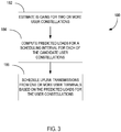
- FIG. 3 illustrates an exemplary method 180 of scheduling uplink transmissions from a plurality of users 20 according to one exemplary embodiment.
- the scheduler 150 at the base station 100 initially determines the interference suppression gain for two or more candidate user constellations being considered (block 182). It will be appreciated that the scheduler 150 has some flexibility in the number of users 20 that can be simultaneously scheduled on the uplink and the data rates assigned to the users 20. Thus, the scheduling decision involves determining a number of users 20 to be scheduled and what data rates to allow for the users 20. The number of users 20 and corresponding data rates of the users 20 corresponds to a user constellation.
- the scheduler 150 computes a predicted load for a scheduling interval for each candidate user constellation as a function of the interference suppression gain for the user constellation (block 184).
- the predicted load is the effective load after interference suppression.
- the scheduler 150 computes an air interface load before interference suppression for each of the candidate user constellations, and adjusts the computed air interface load according to the corresponding interference suppression gain for the user constellation to obtain the predicted load after interference suppression.
- the air interface load before interference suppression may be computed according to Equations (4) - (6).
- the scheduler 150 schedules uplink transmissions from one or more users 20 during the scheduling interval (block 186).
- the scheduler 150 selects one of the candidate user constellations for the scheduling interval based on the predicted loads and the scheduling headroom.
- the selected user constellation may, for example, comprise the one that is below a load threshold and that maximizes throughput.
- the scheduler 150 selects one or more users 20 and assigns data rates according to the selected user constellation.
- One aspect of the invention is the estimation of the interference suppression gains for the candidate user constellations.
- the interference suppressions gains will be different for different user constellations.
- the load estimation circuit 140 simultaneously measures the actual air interface load before interference suppression and the effective load after interference suppression.
- the user constellation used in a given TTI is known to the base station 100.
- the base station 100 can compute the interference suppression gain for the user constellation in a given TTI as the difference between the actual air interface load before interference suppression and the effective load after interference suppression.
- the calculated loads may be computed as the rise over thermal before and after interference suppression.
- the rise over thermal before interference suppression is denoted RoT ( t ) .
- the rise over thermal after interference suppression is denoted RoT IS ( t ) .
- RoT IS ( t ) and RoT ( t ) may be converted to corresponding load factors L own IS t and L own ( t ) before computing the interference suppression gain.
- P neighbor ( t ) can be estimated as described below.
- the term P neighbor ( t )/ P N ( t ) can be configured to a preset value at the cost of accuracy.
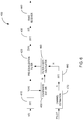
- FIG. 4 illustrates the main functional components of a GRAKE+ receiver 200 which may be used as an interference suppression receiver 110 in embodiments of the present invention.
- the GRAKE+ receiver 200 is a type of linear receiver.
- the GRAKE+ receiver 200 comprises a plurality of RAKE fingers 210 to despread the received signals, and a GRAKE+ combiner 220 to coherently combine the outputs to form symbol estimates.
- the object is to collect signal energy by placing fingers on the strongest path delays and combining the despread values from different fingers coherently using weights that correspond to estimates of the channel coefficient.
- finger placement and combining weight computation are used to both collect signal energy and to suppress interference.
- a covariance estimation circuit 230 estimates the correlations between impairment on different fingers of the GRAKE+ receiver 200 and generates an impairment covariance matrix R ⁇ u .
- a channel estimation circuit 240 generates an estimate ⁇ u of the channel coefficients based on a pilot signal.
- the impairment covariance matrix R ⁇ and channel estimates ⁇ u are input to a weight calculator 250.
- the channel estimates ⁇ u and combining weights ⁇ u are also input to an SINR estimation circuit 260.
- the effect of the covariance matrix is to effectively whiten the correlated interference and remove large spectral peaks from interferers at certain finger locations and for certain antenna elements.
- a chip equalizer receiver is a related type of interference suppression receiver for WCDMA, which is also linear.
- the difference between GRAKE+ receiver 200 and the chip equalizer receiver is the order of certain basic operations.
- some embodiments of the present invention may use a chip equalizer receiver.
- Equation (15) The quantities appearing in Equation (15) are all defined in Annex A. It should be noted that all estimates are obtained at the power control slot rate, i.e. 1500 Hz. This makes the estimates useful for stability monitoring of the inner power control loop in WCDMA.
- the RoT G + relevant for estimation of the interference suppression gain is the maximum of the individual noise rise estimates Ro T u G + .
- FIG. 5 illustrates a FDE receiver 300, which may be used as an interference suppression receiver 110 in some embodiments.
- the FDE receiver 300 performs equalization and interference suppression in the frequency domain.
- the following time domain signal model can be used.
- u denotes the user
- v u is the received signal vector (vector due to multiple antennas)
- h u is the radio channel net response
- z is the desired (transmitted) signal
- i ( t ) is the interference
- n ( t ) denotes thermal noise.
- the received signal is input to a Fast Fourier Transform (FFT) circuit 310.
- the FFT circuit 310 converts the received signal from the time domain to the frequency domain.
- minimum mean-square error (MMSE) equalization is performed on V u ( m ) in the frequency domain by the frequency domain equalizer circuit 320.
- the frequency domain signal V u ( m ) is applied to the frequency domain equalizer circuit 320.
- the frequency domain equalizer circuit 320 multiplies the vector of the received signal V u ( m ) by a filter coefficient matrix W u ( m ) to obtain an estimate Z u of the desired (transmitted signal).
- the equalized signal Z u is then input to an Inverse Fast Fourier Transform (IFFT) circuit 330.
- the IFFT circuit 330 transforms the desired signal Z u from the frequency domain to the time domain to obtain a time domain estimate z ( t ).
- the channel is estimated in the time domain by a channel estimation circuit 340 using the pilot signal as illustrated in Figure 6 .
- the MMSE filter coefficients may be computed in the time domain by a filter coefficient estimation circuit 350 and transformed to the frequency domain by the FFT circuit 360. Methods of computing the MMSE filter coefficients in the time domain are described in E. Dahlman, S. Parkvall, J. Skold and P. Beming,"3G Evolution - HSPA and LTE for mobile broadband" 2:nd edition, Academic Press, 2008 (Section 5.1 ).
- the computation of the MMSE filter coefficients in the frequency domain is less computationally complex that the equivalent computations in the time domain.
- the time domain estimate of the desired signal is used to compute the rise-over-thermal Ro T u FDE for each user 20.
- the quantities in Equation (21) are defined in Annex C. These quantities are estimated at the power control slot rate, e.g. 1500 Hz.
- FIG. 6 illustrates an exemplary FDPE receiver 400, which may be used as an interference suppression receiver 110 in some embodiments.
- the FDPE receiver 400 performs interference whitening in the frequency domain.
- the received signal vector v is input to a Fast Fourier Transform (FFT) circuit 410.
- the FFT circuit 410 translates the received signal vector into the frequency domain.
- Equation (24) are the discrete Fourier transforms of the corresponding terms in Equation (23).
- a pre-equalization filter 420 whitens the received signal vector V ( m ) in the frequency domain.
- the pre-qualized signal Z pre ( m ) is then transformed by the Inverse Fast Fourier Transform (IFFT) 430 to the time domain.
- IFFT Inverse Fast Fourier Transform
- the estimate of the transmitted signal in the time domain is denoted z pre ( t ) .
- the time domain signal is input to a conventional RAKE receiver 440.
- a covariance estimation circuit 450 computes the covariance matrix R ⁇ d ( m ) .
- the covariance matrix is computed according to Equation (27) below, averaged over N different data blocks.
- the channel is estimated in the time domain by a channel estimation circuit 470 as illustrated in Figure 6 .
- the time domain channel estimates are then transformed to the frequency domain by the FFT 480.
- the frequency domain channel estimates and the covariance matrix R ⁇ d ( m ) provided by the covariance estimation circuit 470 are input to a filter coefficient calculator 460, which computes the filter coefficients for the pre-equalization filter 420.
- the neighbor cell interference can be subtracted from the RoT IS to obtain a noise rise, denoted NR IS , that is more relevant for cell stability.
- NR IS noise rise
- the interference suppression receiver 110 comprises of a GRAKE+ receiver
- the noise rise may be denoted NR G + and is given for an individual user by: N R u G + ⁇ S u G + + I u G + + ⁇ u G + N ⁇ ⁇ I u , neighbor G + ⁇ u G + N ⁇ Equation (32) is derived by subtracting the estimate of neighbor cell interference, denoted by I u , neighbor G + , from the numerator in Equation (15).
- neighbor G In order to derive an estimate of the neighbor cell interference after GRAKE+ processing I u , neighbor G + two simplifying assumptions are made. First, it is assumed that the own cell interference dominates over the neighbor cell interference. Second, it is assumed that the neighbor cell interference can be treated as the product of a white noise process.
- the neighbor cell interference after interference suppression processing can be obtained by estimating neighbor cell interference before interference suppression processing and applying a scaling factor ⁇ u G + .
- the neighbor cell interference is normally lower than the own cell interference. Therefore the simplifying assumptions used to compute the neighbor cell interference should have little impact on the final result.
- One method of estimating the neighbor cell interference is described in U.S.
- Patent Application Serial No. 13/376,524 filed on December 6, 2011 discloses use of a Kalman filter to estimate the sum of neighbor cell interference and thermal noise. The thermal noise can be subtracted from this estimate to obtain an estimate of neighbor cell interference.
- the gain table 170 is built and stored in memory.
- the gain table 170 is constructed so that the factors that have shown in Table 1, the factors used for indexing are the number of users 20 in a user constellation, and the data rates of the users 20.
- the number of users 20 can be divided into the number of high data rate users above a bit rate threshold, and the number of low data rate users 20 below the bit rate threshold.
- the granted bit rates can be divided into the granted bit rates of the high data rate users 20 and the total granted bit rate to all of the low rate users 20.
- the number of users 20 and their bit rates is referred to herein as the "user constellation.”
- each entry in the gain table 170 is updated with at least a sliding average of the selected interference suppression gain, in either the RoT or load factor domain.
- the variance can be estimated.
- the interference suppression gain may be advantageous to express as a fraction of the total load, at the air interface or after interference suppression processing. This embodiment is illustrated in Table 1.
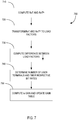
- FIG. 7 illustrates an exemplary procedure 700 for updating the gain table 170.
- the RoT and RoT IS for a TTI are computed (block 710).
- the computation of RoT and RoT IS may be performed for a subset of the users 20 that account for the majority of the load.
- the RoT and RoT IS estimates are then transformed to corresponding load factors L own and L own IS using Equation (12) (block 720).
- the transformation of RoT and RoT IS to load factors L own and L own IS avoids the need to estimate neighbor cell interference.
- the estimation of RoT and RoT IS and transformation to load factors may, in some embodiments, be performed by the load estimation circuit 140.
- the load factors L own and L own IS are then supplied to the gain estimation circuit 160.
- the load estimation circuit 140 may provide RoT and RoT IS to the gain estimation circuit 160, which then transforms RoT and RoT IS to load factors L own and L own IS .
- gain estimation circuit 160 computes a difference of the load factors L own and L own IS (block 730). This difference represents the interference suppression gain, i.e. the reduction in the air interference load due to interference suppression.
- the gain estimation circuit 160 determines the number of users 20 and their bit rates, i.e. the user constellation (block 740). The user constellation may be determined from the TFCI and E-TFCI, which is provided by the scheduler 150.
- the gain estimation circuit 160 then computes the updated interference suppression gain according to Equation (38) and (39) and updates the gain table 170 (block 750).
- the load prediction and scheduling techniques can be applied to time-division multiplexing (TDM) schemes.
- TDM time-division multiplexing
- WCDMA systems typically employ up to 8 hybrid automatic repeated request (HARQ) processes. Each data transmission is assigned to one of the eight HARQ processes. The data received within each HARQ process are processed in parallel.
- TDM can be implemented by using scheduling grants that are valid for specified HARQ processes.
- Figure 8 illustrates the concept of HARQ -specific grants. In Figure 8 , a first set of scheduling grants valid for HARQ processes 0-2 are granted to a first set of users 20, and a second set of scheduling grants valid for HARQ processes are granted to a second set of users 20.
- the RoT, RoT IS , L own , and L own IS is determined separately for each HARQ process. Neighbor cell interference and noise may be computed once for all processes.
- the interference suppression gains for all HARQ processes can be stored in a single table. Equations (36) - (39) are executed once for each process in order to update the gain table.
- Table 2 below shows the structure of the gain table 170 for storing interference suppression gains for multiple HARQ processes.
- Table 2 Structure of Gain Table For Multiple HARQ Processes HARQ # No. of users Data Rates IS Gain as fraction of air interface load Variance 1 3 960, 640, 640 0.15 0.002 2 960, 960 0.30 0.005 ... ... ... ... ... ...
- the scheduling and load estimation techniques herein described may be applied in situations with different carriers and multi-carriers in one band. In such situations, a separate instance of the load prediction and scheduling may be used for each carrier.
- the present invention provides a more accurate estimate of the effective load for interference suppression receivers, which may be used for scheduling users 20 on the uplink.
- the accurate estimation of the uplink load makes it possible to control the uplink load and operate closer to the pole capacity. As a result, the users will see an increase in data rates and uplink capacity will be increased.
- Equations (A2) and (A3) have two main implications; one indicating how power measurements can be done and one indicating the scale factor problem which is addressed below.
- S u , k G + can also be expressed starting with the antenna power
- 2 h ⁇ u H h ⁇ u
- 2 , in which case S u , k G + w ⁇ u H w ⁇ u
- This latter setting is used in the link simulations used for validation of the concept.
- the algorithmic development that follows does however use the definitions (A4)-(A8).
- the idea here is to rely on the baseline thermal noise power floor estimation algorithm to estimate the thermal noise power floor before any G-rake+ processing.
- a main problem then arises since the thermal noise is scaled by ⁇ u when the sufficient statistics is evaluated. This means that the thermal noise power level will no longer appear constant.
- W pre ( m ) denotes the wideband pre-equalizing filter in the frequency domain
- H ( m ) denotes the wideband net channel response in the frequency domain
- Z ( m ) denotes the wideband transmitted signal in the frequency domain
- I ( m ) denotes the wideband neighbor cell interference in the frequency domain
- N thermal ( m ) denotes the wideband thermal noise floor signal in the frequency domain.
- the star denotes (multi-dimensional) convolution z pre ( t ) denotes the pre-equalized wideband signal in the time domain
- w pre ( t ) denotes the wideband finite impulse response of the pre-equalizing filter in the time domain
- h ( t ) denotes the wideband finite impulse response net channel response in the time domain
- z(t) denotes the wideband transmitted signal in the time domain
- i ( t ) denotes the wideband neighbor cell interference in the time domain
- n thermal ( t ) denotes the wideband thermal noise floor signal in the time domain. All signal quantities are here given before the pre-equalization step.
- RoT FDPE t z pre H t z pre t E w pre t * n thermal t H w pre t * n thermal t
- the numerator of (B3) is straightforward to compute. Noting that the time scale for the RoT measurement in WCDMA is normally a transmission time interval (TTI), it follows that the numerator of (14) can be computed e.g. by an average of time samples over the TTI of interest (typically 2 ms or 10 ms).
- TTI transmission time interval
- N ⁇ a thermal denotes the estimated thermal noise floor of antenna branch a, before pre-equalization.
- Exemplary noise estimation algorithms are described in T. Wigren and P. Hellqvist, "Estimation of uplink WCDMA load in a single RBS", Proc.IEEE VTC-2007 Fall, Baltimore, MD, USA, Oct. 1-3, 2007 ; T. Wigren, “Soft uplink load estimation in WCDMA", IEEE Trans Veh. Tech., March, 2009 ; and T. Wigren, “Recursive noise floor estimation in WCDMA", IEEE Trans. Veh. Tech., vol. 59, no. 5, pp. 2615-2620, 2010 .One algorithm is needed for each antenna branch.
- W u ( m ) denotes the wideband MMSE equalizing filter in the frequency domain
- H u ( m ) denotes the wideband net channel response in the frequency domain
- Z ( m ) denotes the wideband transmitted signal in the frequency domain
- I ( m ) denotes the wideband neighbor cell interference in the frequency domain
- N thermal ( m ) denotes the wideband thermal noise floor signal in the frequency domain.
- the numerator of (C3) is straightforward to compute. Noting that the time scale for the RoT measurement in WCDMA is normally a transmission time interval (TTI), it follows that the numerator of (12) can be computed e.g. by an average of time samples over the TTI of interest (typically 2 ms or 10 ms).
- TTI transmission time interval
- N ⁇ a thermal denotes the estimated thermal noise floor of antenna branch a, before pre-equalization. This means that prior art noise floor estimation algorithms of [1] - [3] can be re-used. One algorithm is needed for each antenna branch.
Landscapes
- Engineering & Computer Science (AREA)
- Computer Networks & Wireless Communication (AREA)
- Signal Processing (AREA)
- Mobile Radio Communication Systems (AREA)
Claims (15)
- Procédé de planification de transmissions de liaison montante d'une pluralité d'utilisateurs à une station de base dans un réseau de communication sans fil, le procédé comprenant :l'estimation (182) de gains de suppression d'interférences pour deux constellations d'utilisateurs candidates ou plus, dans lequel le gain de suppression d'interférences est défini en tant que mesure de réduction de charge due à une suppression d'interférences dans des signaux reçus et dans lequel la constellation d'utilisateurs candidate est définie par un nombre d'utilisateurs et par des débits de données correspondants ;le calcul (184) de charges prédites pour un intervalle de planification pour chacune des deux constellations d'utilisateurs candidates ou plus en fonction des gains de suppression d'interférences estimés pour les constellations d'utilisateurs candidates ;la sélection d'une des constellations d'utilisateurs candidates pour l'intervalle de planification sur la base des charges prédites ; etla planification (186) de transmissions de liaison montante depuis un ensemble d'utilisateurs durant l'intervalle de planification selon la constellation d'utilisateurs sélectionnée.
- Procédé selon la revendication 1, dans lequel la planification de transmissions de liaison montante depuis l'ensemble d'utilisateurs selon la constellation d'utilisateurs sélectionnée comprend la planification d'un nombre prédéterminé d'utilisateurs et l'attribution de débits binaires correspondants aux utilisateurs planifiés selon la constellation d'utilisateurs sélectionnée.
- Procédé selon l'une quelconque des revendications 1 et 2, dans lequel le calcul des charges prédites pour au moins un intervalle de planification pour chacune des deux constellations d'utilisateurs candidates ou plus comprend :le calcul de charges prédites d'interface hertzienne pour chacune des constellations d'utilisateurs candidates ; etl'ajustement des charges prédites d'interface hertzienne sur la base de gains de suppression d'interférences correspondants pour les constellations d'utilisateurs candidates pour obtenir les charges prédites pour chaque constellation d'utilisateurs candidate.
- Procédé selon l'une quelconque des revendications 1 et 2, dans lequel l'estimation de gains de suppression d'interférences pour deux constellations d'utilisateurs candidates ou plus comprend l'obtention de gains de suppression d'interférences prédéterminés pour les deux constellations d'utilisateurs candidates ou plus à partir d'une table de gains stockée dans une mémoire de la station de base.
- Procédé selon la revendication 4, dans lequel les gains de suppression d'interférences prédéterminés comprennent des gains de suppressions d'interférences moyens pour les deux constellations d'utilisateurs candidates ou plus dans une pluralité d'intervalles de planification.
- Procédé selon la revendication 4, comprenant en outre l'interpolation de gains de suppression d'interférences pour une des deux constellations d'utilisateurs candidates ou plus sans gain de suppression d'interférences correspondant dans la table de gains.
- Procédé selon la revendication 5, comprenant en outre la mise à jour de la table de gains pour inclure des informations pour un intervalle de planification actuel par recalcul d'un ou de plusieurs des gains de suppression d'interférences prédéterminés.
- Procédé selon la revendication 7, dans lequel le recalcul d'un ou de plusieurs des gains de suppression d'interférences prédéterminés comprend :la détermination d'une constellation d'utilisateurs actuelle pour l'intervalle de planification actuel ;le calcul d'un gain de suppression d'interférences pour la constellation d'utilisateurs actuelle ; etle recalcul du gain de suppression d'interférences moyen pour la constellation d'utilisateurs actuelle pour inclure le gain de suppression d'interférences pour l'intervalle de planification actuel.
- Procédé selon la revendication 8, dans lequel la détermination d'une constellation d'utilisateurs actuelle pour l'intervalle de planification actuel comprend :la détermination d'un nombre d'utilisateurs transmettant des données sur la liaison montante dans l'intervalle de planification actuel ; etla détermination des formats de transport pour les utilisateurs transmettant des données sur la liaison montante dans l'intervalle de planification actuel.
- Procédé selon la revendication 8, dans lequel le calcul du gain de suppression d'interférences pour la constellation d'utilisateurs actuelle comprend le calcul d'une différence entre une charge de liaison montante avant suppression d'interférences et une charge de liaison montante après suppression d'interférences.
- Procédé selon la revendication 10, dans lequel le calcul d'une différence entre la charge de liaison montante avant suppression d'interférences et la charge de liaison montante après suppression d'interférences comprend :le calcul d'une élévation du bruit au-dessus du bruit thermique avant suppression d'interférences et d'une élévation du bruit au-dessus du bruit thermique après suppression d'interférences ; etle calcul d'une différence entre l'élévation du bruit au-dessus du bruit thermique avant suppression d'interférences et l'élévation du bruit au-dessus du bruit thermique après suppression d'interférences.
- Procédé selon la revendication 10, dans lequel le calcul d'une différence entre la charge de liaison montante avant suppression d'interférences et la charge de liaison montante après suppression d'interférences comprend :le calcul d'une élévation du bruit au-dessus du bruit thermique avant suppression d'interférences et d'une élévation du bruit au-dessus du bruit thermique après suppression d'interférences ;le calcul d'un facteur de charge avant suppression d'interférences à partir de l'élévation du bruit au-dessus du bruit thermique calculée avant suppression d'interférences ;le calcul d'un facteur de charge après suppression d'interférences à partir de l'élévation du bruit au-dessus du bruit thermique calculée après suppression d'interférences ; etle calcul d'une différence entre le facteur de charge avant suppression d'interférences et le facteur de charge après suppression d'interférences.
- Procédé selon la revendication 11 ou 12, dans lequel l'élévation du bruit au-dessus du bruit thermique après suppression d'interférences est calculée en tant qu'élévation du bruit au-dessus du bruit thermique maximale pour les utilisateurs dans la constellation d'utilisateurs actuelle.
- Procédé selon la revendication 12 ou 13, dans lequel le calcul des facteurs de charge avant et après une suppression d'interférences comprend :l'estimation d'interférences et de bruit thermique de cellules voisines ;le calcul du facteur de charge avant suppression d'interférences en fonction des interférences, du bruit thermique et de l'élévation du bruit au-dessus du bruit thermique de cellules voisines avant suppression d'interférences ; etle calcul du facteur de charge après suppression d'interférences en fonction des interférences, du bruit thermique et de l'élévation du bruit au-dessus du bruit thermique de cellules voisines après suppression d'interférences.
- Station de base (100) dans un réseau de communication sans fil, la station de base comprenant :un récepteur à suppression d'interférences (110) pour supprimer des interférences dans des signaux reçus d'une pluralité d'utilisateurs ; etun circuit de commande (120) incluant un planificateur (150) pour planifier des transmissions de liaison montante depuis les utilisateurs, le planificateur étant configuré pour :estimer des gains de suppression d'interférences pour deux constellations d'utilisateurs candidates ou plus, dans laquelle le gain de suppression d'interférences est défini en tant que mesure de réduction de charge due à une suppression d'interférences dans des signaux reçus etdans laquelle la constellation d'utilisateurs candidate est définie par un nombre d'utilisateurs et de débits de données correspondants ;calculer des charges prédites pour un intervalle de planification pour chacune des deux constellations d'utilisateurs candidates ou plus en fonction des gains de suppression d'interférences estimés pour les constellations d'utilisateurs candidates ;sélectionner une des constellations d'utilisateurs candidates pour l'intervalle de planification sur la base des charges prédites ; etplanifier des transmissions de liaison montante à partir d'un ensemble d'utilisateurs durant l'intervalle de planification selon la constellation d'utilisateurs sélectionnée.
Applications Claiming Priority (3)
| Application Number | Priority Date | Filing Date | Title |
|---|---|---|---|
| US42175410P | 2010-12-10 | 2010-12-10 | |
| US201161448855P | 2011-03-03 | 2011-03-03 | |
| PCT/SE2011/051485 WO2012078105A1 (fr) | 2010-12-10 | 2011-12-08 | Prévision de charge adaptative pour récepteurs de suppression d'interférence |
Publications (3)
| Publication Number | Publication Date |
|---|---|
| EP2649853A1 EP2649853A1 (fr) | 2013-10-16 |
| EP2649853A4 EP2649853A4 (fr) | 2014-07-23 |
| EP2649853B1 true EP2649853B1 (fr) | 2018-10-10 |
Family
ID=46199324
Family Applications (1)
| Application Number | Title | Priority Date | Filing Date |
|---|---|---|---|
| EP11846605.1A Not-in-force EP2649853B1 (fr) | 2010-12-10 | 2011-12-08 | Prévision de charge adaptative pour récepteurs de suppression d'interférence |
Country Status (3)
| Country | Link |
|---|---|
| US (1) | US9320053B2 (fr) |
| EP (1) | EP2649853B1 (fr) |
| WO (1) | WO2012078105A1 (fr) |
Families Citing this family (18)
| Publication number | Priority date | Publication date | Assignee | Title |
|---|---|---|---|---|
| US20110090820A1 (en) | 2009-10-16 | 2011-04-21 | Osama Hussein | Self-optimizing wireless network |
| US9894664B2 (en) * | 2010-12-10 | 2018-02-13 | Telefonaktiebolaget L M Ericsson (Publ) | Uplink scheduling when using interference suppression |
| US8782211B1 (en) * | 2010-12-21 | 2014-07-15 | Juniper Networks, Inc. | Dynamically scheduling tasks to manage system load |
| US8509762B2 (en) | 2011-05-20 | 2013-08-13 | ReVerb Networks, Inc. | Methods and apparatus for underperforming cell detection and recovery in a wireless network |
| EP2754271B1 (fr) | 2011-09-09 | 2019-11-13 | Reverb Networks Inc. | Procédés et appareil pour mettre en oeuvre un gestionnaire de réseaux à optimisation-organisation automatique |
| US9258719B2 (en) | 2011-11-08 | 2016-02-09 | Viavi Solutions Inc. | Methods and apparatus for partitioning wireless network cells into time-based clusters |
| US9264316B2 (en) | 2011-11-28 | 2016-02-16 | Telefonaktiebolaget L M Ericsson (Publ) | Method and network node |
| US20130195166A1 (en) * | 2012-01-27 | 2013-08-01 | Telefonaktiebolaget Lm Ericsson (Publ) | Robust Frequency-Domain Equalization in Communications Receivers |
| US9008722B2 (en) | 2012-02-17 | 2015-04-14 | ReVerb Networks, Inc. | Methods and apparatus for coordination in multi-mode networks |
| US9473332B2 (en) * | 2012-04-27 | 2016-10-18 | The Royal Institution For The Advancement Of Learning / Mcgill University | Methods and devices for communications systems using multiplied rate transmission |
| US9307414B2 (en) * | 2012-05-03 | 2016-04-05 | Blackberry Limited | Co-existence aware rate support |
| US9295009B2 (en) * | 2012-05-23 | 2016-03-22 | Telefonaktiebolaget L M Ericsson (Publ) | Transcendental function look-up tables for thermal noise power floor estimation |
| ES2440170B1 (es) * | 2012-07-27 | 2015-03-11 | Telefonica Sa | Metodo para implementar un mecanismo de equilibrado de carga de celula en redes inalambricas |
| US9301172B2 (en) * | 2012-10-19 | 2016-03-29 | Telefonaktiebolaget Lm Ericsson (Publ) | Method, apparatus, and system for interference and noise estimation |
| WO2014148965A1 (fr) * | 2013-03-22 | 2014-09-25 | Telefonaktiebolaget L M Ericsson (Publ) | Estimation de brouillage et dispositifs correspondants |
| JP6070417B2 (ja) * | 2013-05-29 | 2017-02-01 | 富士通株式会社 | 無線通信装置、重み係数演算方法、および重み係数演算プログラム |
| US9113353B1 (en) | 2015-02-27 | 2015-08-18 | ReVerb Networks, Inc. | Methods and apparatus for improving coverage and capacity in a wireless network |
| US10389616B2 (en) | 2016-09-06 | 2019-08-20 | Spectrum Effect Inc. | Method and system for detecting interference to wireless networks |
Family Cites Families (20)
| Publication number | Priority date | Publication date | Assignee | Title |
|---|---|---|---|---|
| US6937676B2 (en) | 2000-10-27 | 2005-08-30 | Hitachi Kokusai Electric Inc. | Interference-signal removing apparatus |
| TW200307432A (en) | 2002-04-15 | 2003-12-01 | Matsushita Electric Industrial Co Ltd | The receiving device and the method thereof |
| FI20055469A0 (fi) * | 2005-09-02 | 2005-09-02 | Nokia Corp | Menetelmä ja järjestely radioresurssien hallintaan |
| CN100428830C (zh) | 2006-08-08 | 2008-10-22 | 华为技术有限公司 | 移动通信系统中邻区干扰抑制方法及基站节点 |
| CN101512940B (zh) | 2006-09-25 | 2012-10-10 | 艾利森电话股份有限公司 | 用于存储器有效的噪声基底估计的方法和设备 |
| EP2109947B1 (fr) * | 2007-02-05 | 2016-04-13 | Telefonaktiebolaget LM Ericsson (publ) | Estimation de charge à l'aide d'une puissance de liaison montante programmée |
| KR101005233B1 (ko) | 2007-03-14 | 2010-12-31 | 더 보드 오브 리전츠 오브 더 유니버시티 오브 텍사스 시스템 | 다중 안테나 시스템에서 간섭 제거 장치 및 방법 |
| CN101282566B (zh) | 2007-04-03 | 2011-10-26 | 中兴通讯股份有限公司 | 一种干扰抑制方法 |
| WO2008147269A1 (fr) | 2007-05-31 | 2008-12-04 | Telefonaktiebolaget Lm Ericsson (Publ) | Procédé et système de communication |
| US8676124B2 (en) * | 2007-09-28 | 2014-03-18 | Qualcomm Incorporated | Scheduling based on effective target load with interference cancellation in a wireless communication system |
| US8264975B2 (en) | 2008-02-20 | 2012-09-11 | Qualcomm Incorporated | FFT-based estimation of thermal noise and rise over thermal in a wireless communication system |
| US8605842B2 (en) | 2009-06-11 | 2013-12-10 | Telefonaktiebolaget L M Ericsson (Publ) | Load estimation in interference whitening systems |
| US9276683B2 (en) | 2009-09-08 | 2016-03-01 | Telefonaktiebolaget L M Ericsson (Publ) | Load estimation in wireless communication |
| US8665937B2 (en) | 2009-12-10 | 2014-03-04 | Telefonaktiebolaget L M Ericsson (Publ) | Load estimation in wireless communication |
| KR20110091093A (ko) | 2010-02-05 | 2011-08-11 | 삼성전자주식회사 | 무선 이동통신 시스템의 상향링크 간섭제어 방법 및 장치 |
| US8670478B2 (en) | 2010-06-10 | 2014-03-11 | Telefonaktiebolaget L M Ericsson (Publ) | Load estimation in frequency domain pre-equalization systems |
| US8483260B2 (en) | 2010-09-29 | 2013-07-09 | Telefonaktiebolaget Lm Ericsson (Publ) | Covariance factor matrix reuse |
| WO2012074475A1 (fr) | 2010-12-03 | 2012-06-07 | Telefonaktiebolaget L M Ericsson (Publ) | Procédé et dispositif de gestion de charges dans des réseaux hétérogènes utilisant des récepteurs à fonction d'antiparasitage |
| US9894664B2 (en) * | 2010-12-10 | 2018-02-13 | Telefonaktiebolaget L M Ericsson (Publ) | Uplink scheduling when using interference suppression |
| CN103262598B (zh) * | 2010-12-10 | 2017-02-15 | 瑞典爱立信有限公司 | 用于异构网络中的干扰管理的信号传输 |
-
2011
- 2011-12-08 EP EP11846605.1A patent/EP2649853B1/fr not_active Not-in-force
- 2011-12-08 US US13/314,775 patent/US9320053B2/en not_active Expired - Fee Related
- 2011-12-08 WO PCT/SE2011/051485 patent/WO2012078105A1/fr not_active Ceased
Non-Patent Citations (1)
| Title |
|---|
| None * |
Also Published As
| Publication number | Publication date |
|---|---|
| US9320053B2 (en) | 2016-04-19 |
| EP2649853A4 (fr) | 2014-07-23 |
| EP2649853A1 (fr) | 2013-10-16 |
| WO2012078105A1 (fr) | 2012-06-14 |
| US20120147828A1 (en) | 2012-06-14 |
Similar Documents
| Publication | Publication Date | Title |
|---|---|---|
| EP2649853B1 (fr) | Prévision de charge adaptative pour récepteurs de suppression d'interférence | |
| EP2649737B1 (fr) | Surveillance de la stabilité d'une boucle de réglage de puissance | |
| EP2620018B1 (fr) | Réduction des interférences dans un réseau d'accès radio | |
| EP2476215B1 (fr) | Estimation de charge dans des communications sans fil | |
| EP2580870B1 (fr) | Estimation de la charge dans des systèmes de pré-égalisation dans le domaine fréquentiel | |
| EP2441176B1 (fr) | Estimation de la charge dans des systèmes à blanchissement d'interférences | |
| US9307420B2 (en) | Load estimation in frequency domain pre-equalization systems | |
| EP2647143B1 (fr) | Procédé et dispositif de gestion de charges dans des réseaux hétérogènes utilisant des récepteurs à fonction d'antiparasitage | |
| EP2564529B1 (fr) | Estimation de la charge pour la stabilité de cellules dans des systèmes de blanchiment d'interférences | |
| US8670344B2 (en) | Methods and arrangements for cell stability in a cellular communication system | |
| EP2647248B1 (fr) | Procédé et dispositif pour éviter les encombrements liés aux interférences | |
| EP2641442B1 (fr) | Planification de la charge dans un accès multiple par répartition en code à large bande | |
| EP2572531B1 (fr) | Estimation de charge lors d'un softer handover |
Legal Events
| Date | Code | Title | Description |
|---|---|---|---|
| PUAI | Public reference made under article 153(3) epc to a published international application that has entered the european phase |
Free format text: ORIGINAL CODE: 0009012 |
|
| 17P | Request for examination filed |
Effective date: 20130710 |
|
| AK | Designated contracting states |
Kind code of ref document: A1 Designated state(s): AL AT BE BG CH CY CZ DE DK EE ES FI FR GB GR HR HU IE IS IT LI LT LU LV MC MK MT NL NO PL PT RO RS SE SI SK SM TR |
|
| DAX | Request for extension of the european patent (deleted) | ||
| A4 | Supplementary search report drawn up and despatched |
Effective date: 20140623 |
|
| RIC1 | Information provided on ipc code assigned before grant |
Ipc: H04W 24/02 20090101AFI20140616BHEP |
|
| 17Q | First examination report despatched |
Effective date: 20180511 |
|
| REG | Reference to a national code |
Ref country code: DE Ref legal event code: R079 Ref document number: 602011052863 Country of ref document: DE Free format text: PREVIOUS MAIN CLASS: H04W0072080000 Ipc: H04W0072120000 |
|
| GRAP | Despatch of communication of intention to grant a patent |
Free format text: ORIGINAL CODE: EPIDOSNIGR1 |
|
| RIC1 | Information provided on ipc code assigned before grant |
Ipc: H04W 72/12 20090101AFI20180615BHEP |
|
| INTG | Intention to grant announced |
Effective date: 20180724 |
|
| GRAS | Grant fee paid |
Free format text: ORIGINAL CODE: EPIDOSNIGR3 |
|
| GRAA | (expected) grant |
Free format text: ORIGINAL CODE: 0009210 |
|
| AK | Designated contracting states |
Kind code of ref document: B1 Designated state(s): AL AT BE BG CH CY CZ DE DK EE ES FI FR GB GR HR HU IE IS IT LI LT LU LV MC MK MT NL NO PL PT RO RS SE SI SK SM TR |
|
| REG | Reference to a national code |
Ref country code: GB Ref legal event code: FG4D |
|
| REG | Reference to a national code |
Ref country code: CH Ref legal event code: EP Ref country code: AT Ref legal event code: REF Ref document number: 1052781 Country of ref document: AT Kind code of ref document: T Effective date: 20181015 |
|
| REG | Reference to a national code |
Ref country code: IE Ref legal event code: FG4D Ref country code: DE Ref legal event code: R096 Ref document number: 602011052863 Country of ref document: DE |
|
| REG | Reference to a national code |
Ref country code: NL Ref legal event code: FP |
|
| REG | Reference to a national code |
Ref country code: LT Ref legal event code: MG4D |
|
| REG | Reference to a national code |
Ref country code: AT Ref legal event code: MK05 Ref document number: 1052781 Country of ref document: AT Kind code of ref document: T Effective date: 20181010 |
|
| PG25 | Lapsed in a contracting state [announced via postgrant information from national office to epo] |
Ref country code: PL Free format text: LAPSE BECAUSE OF FAILURE TO SUBMIT A TRANSLATION OF THE DESCRIPTION OR TO PAY THE FEE WITHIN THE PRESCRIBED TIME-LIMIT Effective date: 20181010 Ref country code: HR Free format text: LAPSE BECAUSE OF FAILURE TO SUBMIT A TRANSLATION OF THE DESCRIPTION OR TO PAY THE FEE WITHIN THE PRESCRIBED TIME-LIMIT Effective date: 20181010 Ref country code: NO Free format text: LAPSE BECAUSE OF FAILURE TO SUBMIT A TRANSLATION OF THE DESCRIPTION OR TO PAY THE FEE WITHIN THE PRESCRIBED TIME-LIMIT Effective date: 20190110 Ref country code: BG Free format text: LAPSE BECAUSE OF FAILURE TO SUBMIT A TRANSLATION OF THE DESCRIPTION OR TO PAY THE FEE WITHIN THE PRESCRIBED TIME-LIMIT Effective date: 20190110 Ref country code: LT Free format text: LAPSE BECAUSE OF FAILURE TO SUBMIT A TRANSLATION OF THE DESCRIPTION OR TO PAY THE FEE WITHIN THE PRESCRIBED TIME-LIMIT Effective date: 20181010 Ref country code: IS Free format text: LAPSE BECAUSE OF FAILURE TO SUBMIT A TRANSLATION OF THE DESCRIPTION OR TO PAY THE FEE WITHIN THE PRESCRIBED TIME-LIMIT Effective date: 20190210 Ref country code: AT Free format text: LAPSE BECAUSE OF FAILURE TO SUBMIT A TRANSLATION OF THE DESCRIPTION OR TO PAY THE FEE WITHIN THE PRESCRIBED TIME-LIMIT Effective date: 20181010 Ref country code: ES Free format text: LAPSE BECAUSE OF FAILURE TO SUBMIT A TRANSLATION OF THE DESCRIPTION OR TO PAY THE FEE WITHIN THE PRESCRIBED TIME-LIMIT Effective date: 20181010 Ref country code: FI Free format text: LAPSE BECAUSE OF FAILURE TO SUBMIT A TRANSLATION OF THE DESCRIPTION OR TO PAY THE FEE WITHIN THE PRESCRIBED TIME-LIMIT Effective date: 20181010 Ref country code: LV Free format text: LAPSE BECAUSE OF FAILURE TO SUBMIT A TRANSLATION OF THE DESCRIPTION OR TO PAY THE FEE WITHIN THE PRESCRIBED TIME-LIMIT Effective date: 20181010 |
|
| PG25 | Lapsed in a contracting state [announced via postgrant information from national office to epo] |
Ref country code: SE Free format text: LAPSE BECAUSE OF FAILURE TO SUBMIT A TRANSLATION OF THE DESCRIPTION OR TO PAY THE FEE WITHIN THE PRESCRIBED TIME-LIMIT Effective date: 20181010 Ref country code: AL Free format text: LAPSE BECAUSE OF FAILURE TO SUBMIT A TRANSLATION OF THE DESCRIPTION OR TO PAY THE FEE WITHIN THE PRESCRIBED TIME-LIMIT Effective date: 20181010 Ref country code: RS Free format text: LAPSE BECAUSE OF FAILURE TO SUBMIT A TRANSLATION OF THE DESCRIPTION OR TO PAY THE FEE WITHIN THE PRESCRIBED TIME-LIMIT Effective date: 20181010 Ref country code: PT Free format text: LAPSE BECAUSE OF FAILURE TO SUBMIT A TRANSLATION OF THE DESCRIPTION OR TO PAY THE FEE WITHIN THE PRESCRIBED TIME-LIMIT Effective date: 20190210 Ref country code: GR Free format text: LAPSE BECAUSE OF FAILURE TO SUBMIT A TRANSLATION OF THE DESCRIPTION OR TO PAY THE FEE WITHIN THE PRESCRIBED TIME-LIMIT Effective date: 20190111 |
|
| REG | Reference to a national code |
Ref country code: DE Ref legal event code: R097 Ref document number: 602011052863 Country of ref document: DE |
|
| PG25 | Lapsed in a contracting state [announced via postgrant information from national office to epo] |
Ref country code: DK Free format text: LAPSE BECAUSE OF FAILURE TO SUBMIT A TRANSLATION OF THE DESCRIPTION OR TO PAY THE FEE WITHIN THE PRESCRIBED TIME-LIMIT Effective date: 20181010 Ref country code: CZ Free format text: LAPSE BECAUSE OF FAILURE TO SUBMIT A TRANSLATION OF THE DESCRIPTION OR TO PAY THE FEE WITHIN THE PRESCRIBED TIME-LIMIT Effective date: 20181010 Ref country code: IT Free format text: LAPSE BECAUSE OF FAILURE TO SUBMIT A TRANSLATION OF THE DESCRIPTION OR TO PAY THE FEE WITHIN THE PRESCRIBED TIME-LIMIT Effective date: 20181010 |
|
| REG | Reference to a national code |
Ref country code: CH Ref legal event code: PL |
|
| PLBE | No opposition filed within time limit |
Free format text: ORIGINAL CODE: 0009261 |
|
| STAA | Information on the status of an ep patent application or granted ep patent |
Free format text: STATUS: NO OPPOSITION FILED WITHIN TIME LIMIT |
|
| PG25 | Lapsed in a contracting state [announced via postgrant information from national office to epo] |
Ref country code: RO Free format text: LAPSE BECAUSE OF FAILURE TO SUBMIT A TRANSLATION OF THE DESCRIPTION OR TO PAY THE FEE WITHIN THE PRESCRIBED TIME-LIMIT Effective date: 20181010 Ref country code: LU Free format text: LAPSE BECAUSE OF NON-PAYMENT OF DUE FEES Effective date: 20181208 Ref country code: EE Free format text: LAPSE BECAUSE OF FAILURE TO SUBMIT A TRANSLATION OF THE DESCRIPTION OR TO PAY THE FEE WITHIN THE PRESCRIBED TIME-LIMIT Effective date: 20181010 Ref country code: SM Free format text: LAPSE BECAUSE OF FAILURE TO SUBMIT A TRANSLATION OF THE DESCRIPTION OR TO PAY THE FEE WITHIN THE PRESCRIBED TIME-LIMIT Effective date: 20181010 Ref country code: SK Free format text: LAPSE BECAUSE OF FAILURE TO SUBMIT A TRANSLATION OF THE DESCRIPTION OR TO PAY THE FEE WITHIN THE PRESCRIBED TIME-LIMIT Effective date: 20181010 Ref country code: MC Free format text: LAPSE BECAUSE OF FAILURE TO SUBMIT A TRANSLATION OF THE DESCRIPTION OR TO PAY THE FEE WITHIN THE PRESCRIBED TIME-LIMIT Effective date: 20181010 |
|
| 26N | No opposition filed |
Effective date: 20190711 |
|
| REG | Reference to a national code |
Ref country code: IE Ref legal event code: MM4A |
|
| REG | Reference to a national code |
Ref country code: BE Ref legal event code: MM Effective date: 20181231 |
|
| PG25 | Lapsed in a contracting state [announced via postgrant information from national office to epo] |
Ref country code: FR Free format text: LAPSE BECAUSE OF NON-PAYMENT OF DUE FEES Effective date: 20181210 Ref country code: IE Free format text: LAPSE BECAUSE OF NON-PAYMENT OF DUE FEES Effective date: 20181208 Ref country code: SI Free format text: LAPSE BECAUSE OF FAILURE TO SUBMIT A TRANSLATION OF THE DESCRIPTION OR TO PAY THE FEE WITHIN THE PRESCRIBED TIME-LIMIT Effective date: 20181010 |
|
| PG25 | Lapsed in a contracting state [announced via postgrant information from national office to epo] |
Ref country code: BE Free format text: LAPSE BECAUSE OF NON-PAYMENT OF DUE FEES Effective date: 20181231 |
|
| PG25 | Lapsed in a contracting state [announced via postgrant information from national office to epo] |
Ref country code: LI Free format text: LAPSE BECAUSE OF NON-PAYMENT OF DUE FEES Effective date: 20181231 Ref country code: CH Free format text: LAPSE BECAUSE OF NON-PAYMENT OF DUE FEES Effective date: 20181231 |
|
| PG25 | Lapsed in a contracting state [announced via postgrant information from national office to epo] |
Ref country code: MT Free format text: LAPSE BECAUSE OF NON-PAYMENT OF DUE FEES Effective date: 20181208 |
|
| PG25 | Lapsed in a contracting state [announced via postgrant information from national office to epo] |
Ref country code: TR Free format text: LAPSE BECAUSE OF FAILURE TO SUBMIT A TRANSLATION OF THE DESCRIPTION OR TO PAY THE FEE WITHIN THE PRESCRIBED TIME-LIMIT Effective date: 20181010 |
|
| PG25 | Lapsed in a contracting state [announced via postgrant information from national office to epo] |
Ref country code: MK Free format text: LAPSE BECAUSE OF NON-PAYMENT OF DUE FEES Effective date: 20181010 Ref country code: HU Free format text: LAPSE BECAUSE OF FAILURE TO SUBMIT A TRANSLATION OF THE DESCRIPTION OR TO PAY THE FEE WITHIN THE PRESCRIBED TIME-LIMIT; INVALID AB INITIO Effective date: 20111208 Ref country code: CY Free format text: LAPSE BECAUSE OF FAILURE TO SUBMIT A TRANSLATION OF THE DESCRIPTION OR TO PAY THE FEE WITHIN THE PRESCRIBED TIME-LIMIT Effective date: 20181010 |
|
| PGFP | Annual fee paid to national office [announced via postgrant information from national office to epo] |
Ref country code: GB Payment date: 20211227 Year of fee payment: 11 Ref country code: DE Payment date: 20211227 Year of fee payment: 11 |
|
| PGFP | Annual fee paid to national office [announced via postgrant information from national office to epo] |
Ref country code: NL Payment date: 20211226 Year of fee payment: 11 |
|
| REG | Reference to a national code |
Ref country code: DE Ref legal event code: R119 Ref document number: 602011052863 Country of ref document: DE |
|
| REG | Reference to a national code |
Ref country code: NL Ref legal event code: MM Effective date: 20230101 |
|
| GBPC | Gb: european patent ceased through non-payment of renewal fee |
Effective date: 20221208 |
|
| PG25 | Lapsed in a contracting state [announced via postgrant information from national office to epo] |
Ref country code: NL Free format text: LAPSE BECAUSE OF NON-PAYMENT OF DUE FEES Effective date: 20230101 |
|
| PG25 | Lapsed in a contracting state [announced via postgrant information from national office to epo] |
Ref country code: GB Free format text: LAPSE BECAUSE OF NON-PAYMENT OF DUE FEES Effective date: 20221208 Ref country code: DE Free format text: LAPSE BECAUSE OF NON-PAYMENT OF DUE FEES Effective date: 20230701 |