EP2649937B1 - Vorrichtung zur Ent- und/oder Aufnahme von Körperflüssigkeiten, insbesondere Blut - Google Patents
Vorrichtung zur Ent- und/oder Aufnahme von Körperflüssigkeiten, insbesondere Blut Download PDFInfo
- Publication number
- EP2649937B1 EP2649937B1 EP13001313.9A EP13001313A EP2649937B1 EP 2649937 B1 EP2649937 B1 EP 2649937B1 EP 13001313 A EP13001313 A EP 13001313A EP 2649937 B1 EP2649937 B1 EP 2649937B1
- Authority
- EP
- European Patent Office
- Prior art keywords
- cap
- tube
- cannula
- small tube
- vacuum
- Prior art date
- Legal status (The legal status is an assumption and is not a legal conclusion. Google has not performed a legal analysis and makes no representation as to the accuracy of the status listed.)
- Active
Links
Images

Classifications
-
- A—HUMAN NECESSITIES
- A61—MEDICAL OR VETERINARY SCIENCE; HYGIENE
- A61B—DIAGNOSIS; SURGERY; IDENTIFICATION
- A61B5/00—Measuring for diagnostic purposes; Identification of persons
- A61B5/15—Devices for taking samples of blood
- A61B5/153—Devices specially adapted for taking samples of venous or arterial blood, e.g. with syringes
- A61B5/154—Devices using pre-evacuated means
- A61B5/1545—Devices using pre-evacuated means comprising means for indicating vein or arterial entry
-
- A—HUMAN NECESSITIES
- A61—MEDICAL OR VETERINARY SCIENCE; HYGIENE
- A61B—DIAGNOSIS; SURGERY; IDENTIFICATION
- A61B5/00—Measuring for diagnostic purposes; Identification of persons
- A61B5/15—Devices for taking samples of blood
- A61B5/150007—Details
- A61B5/150015—Source of blood
- A61B5/15003—Source of blood for venous or arterial blood
-
- A—HUMAN NECESSITIES
- A61—MEDICAL OR VETERINARY SCIENCE; HYGIENE
- A61B—DIAGNOSIS; SURGERY; IDENTIFICATION
- A61B5/00—Measuring for diagnostic purposes; Identification of persons
- A61B5/15—Devices for taking samples of blood
- A61B5/150007—Details
- A61B5/150351—Caps, stoppers or lids for sealing or closing a blood collection vessel or container, e.g. a test-tube or syringe barrel
-
- A—HUMAN NECESSITIES
- A61—MEDICAL OR VETERINARY SCIENCE; HYGIENE
- A61B—DIAGNOSIS; SURGERY; IDENTIFICATION
- A61B5/00—Measuring for diagnostic purposes; Identification of persons
- A61B5/15—Devices for taking samples of blood
- A61B5/150007—Details
- A61B5/150374—Details of piercing elements or protective means for preventing accidental injuries by such piercing elements
- A61B5/150381—Design of piercing elements
- A61B5/150389—Hollow piercing elements, e.g. canulas, needles, for piercing the skin
-
- A—HUMAN NECESSITIES
- A61—MEDICAL OR VETERINARY SCIENCE; HYGIENE
- A61B—DIAGNOSIS; SURGERY; IDENTIFICATION
- A61B5/00—Measuring for diagnostic purposes; Identification of persons
- A61B5/15—Devices for taking samples of blood
- A61B5/150007—Details
- A61B5/150374—Details of piercing elements or protective means for preventing accidental injuries by such piercing elements
- A61B5/150381—Design of piercing elements
- A61B5/150473—Double-ended needles, e.g. used with pre-evacuated sampling tubes
- A61B5/150496—Details of construction of hub, i.e. element used to attach the double-ended needle to a piercing device or sampling device
-
- A—HUMAN NECESSITIES
- A61—MEDICAL OR VETERINARY SCIENCE; HYGIENE
- A61B—DIAGNOSIS; SURGERY; IDENTIFICATION
- A61B5/00—Measuring for diagnostic purposes; Identification of persons
- A61B5/15—Devices for taking samples of blood
- A61B5/150007—Details
- A61B5/150732—Needle holders, for instance for holding the needle by the hub, used for example with double-ended needle and pre-evacuated tube
Definitions
- the invention relates to a device for removal and / or uptake of body fluids, in particular blood, comprising a tube which is vacuum sealed at its upper, open end and provided there with a cap, which is used to hold a cannula supported by a needle holder or Double cannula preferably has a dome-like approach and receives at its front end pierceable by the cannula membrane.
- Blood collection tubes where the tube is evacuated by the manufacturer to draw blood, are commercially available. They must be so vacuum-tight that they can absorb the minimum filling volume specified in DIN EN 14820 over the entire shelf life of the product.
- a working on the vacuum principle tube or container can, as from the EP 1 356 302 B1 known, consist of glass, plastic or other gas-impermeable and transparent materials.
- Such a plug inserted into the tube requires special measures, on the one hand to ensure the required vacuum tightness and on the other hand to prevent that after withdrawal of blood when removing the needle holder or the tube, the plug is pulled out of the tube.
- these plugs entail the risk of so-called aerosol formation, that is to say, when the plug is removed, it is possible, in particular, to spray microscopically small blood droplets which can be potentially infectious and endanger laboratory staff.
- the invention is therefore an object of the invention to provide a generic device that ensures improved, greater reliability and ease of use with a simple design.
- This object is achieved in that the formed with means for compound cap and the tube of a gas-impermeable material, preferably PET, and between the cap and the tube, a plug-free sealing element is formed.
- a gas-impermeable material preferably PET
- a Aufschraubvorgang or solving a preferred here rotatably guided connection such as in particular in the form of a screw thread, ie using a screw cap, but optionally also as a locking connection, for example a bayonet closure, regularly ensures a controlled opening behavior.
- a preferred proposal of the invention provides an enclosed between the cap and the tube, provided with a central passage opening annular sealing element.
- the sealing element in particular an O-ring or a sealing disk, can be supported on or at the opening edge of the tube, wherein it is fixed by the screwed-on cap.
- Alternative sealing elements can be embodied as conical sections or sealing lips formed on the cap and / or the tube. In any case, there is a plug-free, vacuum-tight connection.
- the cap is made of a transparent material, so that it is possible to achieve a blood flow which can be observed from the outset without any restriction.
- the material used for the gas-impermeable blood sampling device is preferably PET.
- the same materials for the tube and the cap ensure the gas impermeability of the overall device, and the plug-free sealing element design meets the requirements for vacuum tightness.
- a flexible membrane pierceable by the cannula or double cannula is arranged at the upper, free end.
- the membrane of the embodiment according to the invention is consistent with the other parts of gas-impermeable material.
- it can, in order to enable an indication of additives added to the vacuum tube, for example, be determined in color (color coding).
- the base material for the membrane may be rubber or the like.
- the dome-like projection of the cap is provided on its outer circumference with locking means for attaching a commercially available cannula, as are usual in working on the aspiration principle blood collection systems.
- This embodiment makes it possible for the later user to combine vacuum blood collection tubes according to the invention and those which work according to the aspiration principle using the same cannula.
- a vacuum tube 2 having a screw thread at its upper, open end and including one on the opening edge of the tube 2 supporting gasket 4 is closed by a screw cap 5.
- the screw cap 5 has a dome-like projection 6 with locking means 8 provided on its outer circumference for fixing a plugged, not shown, complementary counter-latching needle or cannula holder.
- a pierceable for blood collection from the cannula of the needle holder membrane 7 is inserted.
- the sealing disk 4 provided in the exemplary embodiment as a plug-free sealing element has a central passage opening 9, through which the blood can flow into the tube or vacuum tube 2 after the membrane 7 has been pierced.
- the screw cap 5 including the dome-like projection 6 is like the vacuum tube itself made of gas-impermeable material, the vacuum-tightness of the pre-assembled with the exception of the needle holder system ( Fig. 1 ) is achieved by the interaction of all gas impermeable components.
- the gasket 4 is held with bias in the screw cap 5 and pressed firmly when screwing the cap on the opening edge of the vacuum tube 2.
- the recognition of the blood flow is not hindered by a thick plug, and at the time of removal the first drops of blood are already visible. This is further supported and improved if not only the vacuum tube 2 but also the screw cap 5 is made of transparent material.
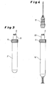
- FIG. 3 shows as a detail as described above vacuum-tight sealed vacuum tube 2 in an overall view, wherein the screw cap 5 is formed on its dome-like projection 6 with locking means 10, as they are also for attaching a needle holder 11 in a working Aspirationskal, in Fig. 4 illustrated blood collection tube 12 are common.
- the synopsis of 3 and 4 illustrates that both a vacuum tube 2 as well as a suitable for aspiration blood collection tube 12 can be equipped with a uniform needle holder 11.
Landscapes
- Health & Medical Sciences (AREA)
- Life Sciences & Earth Sciences (AREA)
- Heart & Thoracic Surgery (AREA)
- Medical Informatics (AREA)
- Biophysics (AREA)
- Pathology (AREA)
- Engineering & Computer Science (AREA)
- Biomedical Technology (AREA)
- Hematology (AREA)
- Physics & Mathematics (AREA)
- Molecular Biology (AREA)
- Surgery (AREA)
- Animal Behavior & Ethology (AREA)
- General Health & Medical Sciences (AREA)
- Public Health (AREA)
- Veterinary Medicine (AREA)
- Vascular Medicine (AREA)
- Measurement Of The Respiration, Hearing Ability, Form, And Blood Characteristics Of Living Organisms (AREA)
Description
- Die Erfindung betrifft eine Vorrichtung zur Ent- und/oder Aufnahme von Körperflüssigkeiten, insbesondere Blut, umfassend ein Röhrchen, das an seinem oberen, offenen Ende vakuumdicht verschlossen und dort mit einer Kappe versehen ist, die zum Halten einer von einem Nadelhalter getragenen Kanüle bzw. Doppelkanüle vorzugsweise einen domartigen Ansatz aufweist und an ihrem vorderen Ende eine von der Kanüle durchstechbare Membrane aufnimmt.
- Blutsammelröhrchen, bei denen das Röhrchen herstellerseitig evakuiert wird, um Blut zu ziehen, sind handelsüblich. Sie müssen derart vakuumdicht sein, dass sie das in der DIN EN 14820 festgelegte Mindestfüllvolumen über die gesamte Haltbarkeit des Produktes hinweg aufnehmen können. Ein nach dem Vakuumprinzip arbeitendes Röhrchen bzw. Behälter kann, wie aus der
EP 1 356 302 B1 bekannt, aus Glas, Kunststoff oder anderen gasundurchlässigen und durchsichtigen Materialien bestehen. Zum Befestigen bzw. Aufstecken und Halten eines Kanülenhalters auf einem bzw. einen dort domartigen Ansatz einer Kappe sind durch dieEP 1 465 528 B1 verschiedene Varianten von am Außenumfang des domartigen Ansatzes vorgesehenen Verriegelungsmitteln bekannt geworden. - Der Verschluss solcher Vakuumröhrchen erfolgt durch einen dicken Stopfen, in der Regel hergestellt aus Gummi, der in seinem Zentrum eine Materialverdünnung aufweist, welche beim Aufsetzen des Nadelhalters von der Kanüle durchstochen wird.
- Ein derartiger in das Röhrchen eingesteckter Verschlussstopfen erfordert besondere Maßnahmen, um einerseits die geforderte Vakuumdichtheit zu gewährleisten und andererseits zu verhindern, dass nach der Blutentnahme beim Abziehen des Nadelhalters bzw. des Röhrchens der Stopfen mit aus dem Röhrchen herausgezogen wird. Außerdem bergen diese Verschlussstopfen das Risiko einer sogenannten Aerosolbildung in sich, d.h., dass beim Entfernen des Stopfens insbesondere mikroskopisch kleine Blutströpfchen verspritzt werden können, die potentiell infektiös wirken und Labormitarbeiter gefährden können.
- Der Erfindung liegt daher die Aufgabe zugrunde, eine gattungsgemäße Vorrichtung zu schaffen, die bei einfacher Bauweise eine verbesserte, größere Betriebssicherheit und Bedienungsfreundlichkeit gewährleistet.
- Diese Aufgabe wird erfindungsgemäß dadurch gelöst, dass die mit Mitteln zur Verbindung ausgebildete Kappe und das Röhrchen aus einem gasundurchlässigen Material, vorzugsweise PET, bestehen und zwischen der Kappe und dem Röhrchen ein stopfenloses Dichtelement ausgebildet ist.
- Es wird damit nicht nur ein stopfenloses Vakuumröhrchen ermöglicht, so dass ein dicker, viel Werkstoff erfordernder Stopfen entfallen kann, sondern die Handhabung wird gleichzeitig deutlich verbessert, weil bei der Entnahme schon gleich die ersten Blutstropfen zu sehen sind. Denn ein den Blutfluss zunächst verdeckender Stopfen muss nicht mehr passiert werden. Schließlich kann praktisch kein Aerosoleffekt auftreten, wenn die Kappe von dem Vakuumröhrchen getrennt wird. Ein Aufschraubvorgang bzw. das Lösen einer hier bevorzugten drehbar geführten Verbindung, wie insbesondere in Form eines Schraubgewindes, d.h. unter Verwendung einer Schraubkappe, optional aber auch als Rastverbindung beispielsweise ein Bajonettverschluss, gewährleistet regelmäßig ein kontrolliertes Öffnungsverhalten.
- Ein bevorzugter Vorschlag der Erfindung sieht ein zwischen der Kappe und dem Röhrchen eingeschlossenes, mit einer zentrischen Durchgangsöffnung versehenes ringförmiges Dichtelement vor. Das Dichtelement, insbesondere ein O-Ring oder eine Dichtscheibe, kann sich auf dem bzw. an dem Öffnungsrand des Röhrchens abstützen, wobei es von der aufgeschraubten Kappe fixiert wird. Alternative Dichtelemente können als an der Kappe und/oder dem Röhrchen angeformte konische Abschnitte oder Dichtlippen ausgeführt werden. In jedem Fall liegt eine stopfenlose, vakuumdichte Verbindung vor.
- Nach einer bevorzugten Ausführung der Erfindung besteht auch die Kappe aus einem durchsichtigen Material, so dass sich ein von vornherein ohne jegliche Einschränkung einsehbarer Blutfluss erreichen lässt. Als Material für die gasundurchlässige Blutentnahmevorrichtung kommt vorzugsweise PET zum Einsatz. Die für das Röhrchen und die Kappe gleichen Materialien gewährleisten die Gasundurchlässigkeit der Gesamtvorrichtung, und die stopfenlose Dichtelement-Ausbildung erfüllt die Anforderungen an die Vakuumdichtheit.
- Bei einem zum Verbinden mit dem Kanülenhalter auf der Schraubkappe ausgebildeten domartigen Ansatz ist, wie bei Schraubkappen von Blutentnahmevorrichtungen nach dem Aspirationssystem an sich bekannt, am oberen, freien Ende eine von der Kanüle bzw. Doppelkanüle durchstechbare, nachgiebige Membrane angeordnet. Die Membrane der erfindungsgemäßen Ausgestaltung besteht übereinstimmend mit den übrigen Teilen aus gasundurchlässigem Material. Vorteilhaft kann sie, um sofort einen Hinweis auf in das Vakuumröhrchen beispielsweise zugegebene Additive zu ermöglichen, bestimmt farbig vorgesehen werden (Farbkodierung). Das Grundmaterial für die Membrane kann Gummi oder dergleichen sein.
- In einer vorteilhaften Ausführungsform ist der domartige Ansatz der Kappe an seinem Außenumfang mit Verriegelungsmitteln zum Befestigen einer handelsüblichen Kanüle, wie sie bei nach dem Aspirationsprinzip arbeitenden Blutentnahmesystemen üblich sind, versehen. Durch diese Ausgestaltung wird es dem späteren Anwender ermöglicht, erfindungsgemäße Vakuumblutentnahmeröhrchen und solche, die nach dem Aspirationsprinzip arbeiten, unter Verwendung der gleichen Kanüle, miteinander zu kombinieren.
- Weitere Einzelheiten und Merkmale der Erfindung ergeben sich aus den Patentansprüchen und der nachfolgenden Beschreibung eines in der Zeichnung dargestellten Ausführungsbeispiels. Es zeigen:
- Fig. 1
- in einem Längsschnitt ein fertig vormontiertes Vakuumröhrchen, das unter Einschluss einer Dichtscheibe als stopfenloses Dichtelement von einer im beschriebenen Ausführungsbeispiel aufgeschraubten, einen domartigen Ansatz aufweisenden Kappe verschlossen wird;
- Fig. 2
- das Vakuumröhrchen der
Fig. 1 in einer explosiven Darstellung; - Fig. 3
- in einer Gesamtansicht als Einzelheit ein durch eine einen domartigen Ansatz aufweisende Kappe verschlossenes Vakuumröhrchen; und
- Fig. 4
- in einer perspektivischen Gesamtansicht ein nach dem Aspirationsprinzip arbeitendes, mit einer Kappe wie in
Fig. 3 verschlossenes Blutentnahmeröhrchen und dazu gehörigen Kanülenhalter. - Von einer Blutentnahmevorrichtung 1 ist in den
Fig. 1 und 2 als Einzelheit ein Vakuumröhrchen 2 gezeigt, das an seinem oberen, offenen Ende ein Schraubgewinde aufweist und unter Einschluss einer sich auf dem Öffnungsrand des Röhrchens 2 abstützenden Dichtscheibe 4 von einer aufgeschraubten Kappe 5 verschlossen wird. Die Schraubkappe 5 besitzt einen domartigen Ansatz 6 mit an dessen Außenumfang vorgesehenen Verriegelungsmitteln 8 zum Festlegen eines aufgesteckten, hier nicht dargestellten, komplementäre Gegenriegel aufweisenden Nadel- bzw. Kanülenhalters. Am oberen Ende des domartigen Ansatzes 6 ist eine zur Blutentnahme von der Kanüle des Nadelhalters durchstechbare Membrane 7 eingesetzt. Die im Ausführungsbeispiel als stopfenloses Dichtelement vorgesehene Dichtscheibe 4 weist eine zentrische Durchgangsöffnung 9 auf, durch die hindurch das Blut nach dem Durchstechen der Membrane 7 in das Röhrchen bzw. Vakuumröhrchen 2 hinein fließen kann. - Die Schraubkappe 5 einschließlich des domartigen Ansatzes 6 besteht wie das Vakuumröhrchen selbst aus gasundurchlässigem Material, wobei die Vakuumdichtheit des mit Ausnahme des Nadelhalters vormontierten Systems (
Fig. 1 ) durch das Zusammenwirken aller gasundurchlässigen Komponenten erreicht wird. Beim Fertigmontieren wird die Dichtscheibe 4 mit Vorspannung in der Schraubkappe 5 gehalten und beim Aufschrauben der Kappe fest auf den Öffnungsrand des Vakuumröhrchens 2 angedrückt. Die Erkennbarkeit des Blutflusses wird nicht durch einen dicken Stopfen behindert, und bei der Entnahme sind schon die ersten Blutstropfen zu sehen. Das wird dadurch noch weiter unterstützt und verbessert, wenn nicht nur das Vakuumröhrchen 2, sondern weiterhin auch die Schraubkappe 5 aus durchsichtigem Material besteht. - Die
Fig. 3 zeigt als Einzelheit ein wie vorbeschrieben vakuumdicht verschlossenes Vakuumröhrchen 2 in einer Gesamtansicht, wobei die Schraubkappe 5 an ihrem domartigen Ansatz 6 mit Verriegelungsmitteln 10 ausgebildet ist, wie sie auch zum Befestigen eines Kanülenhalters 11 bei einem nach dem Aspirationsprinzip arbeitenden, inFig. 4 dargestellten Blutentnahmeröhrchen 12 üblich sind. Die Zusammenschau derFig. 3 und 4 verdeutlicht, dass sich sowohl ein Vakuumröhrchen 2 als auch ein zur Aspiration geeignetes Blutentnahmeröhrchen 12 mit einem einheitlichen Kanülenhalter 11 bestücken lässt. -
- 1
- Blutentnahmevorrichtung
- 2
- Vakuumröhrchen/Röhrchen bzw. Behältnis
- 3
- Schraubgewinde
- 4
- Dichtscheibe/Dichtelement
- 5
- Kappe/Schraubkappe bzw. Verschlusskappe
- 6
- domartiger Ansatz
- 7
- Membrane
- 8
- Verriegelungsmittel
- 9
- zentrische Durchgangsöffnung
- 10
- Verriegelungsmittel
- 11
- Kanülenhalter
- 12
- Blutentnahmeröhrchen
Claims (5)
- Vorrichtung zur Ent- und/oder Aufnahme von Körperflüssigkeiten, insbesondere Blut, umfassend ein Röhrchen (2), das an seinem oberen, offenen Ende vakuumdicht verschlossen und dort mit einer Kappe (5) versehen ist, die zum Halten einer von einem Nadelhalter getragenen Kanüle bzw. Doppelkanüle vorzugsweise einen domartigen Ansatz (6) aufweist und an ihrem vorderen Ende eine von der Kanüle durchstechbare Membrane (7) aufnimmt,
dadurch gekennzeichnet,
dass die mit Mitteln zur Verbindung ausgebildete Kappe (5) und das Röhrchen (2) aus einem gasundurchlässigen Material, vorzugsweise PET, bestehen und zwischen der Kappe (5) und dem Röhrchen (2) ein stopfenloses Dichtelement ausgebildet ist. - Vorrichtung nach Anspruch 1,
gekennzeichnet durch
ein zwischen der Kappe (5 und dem Röhrchen (2) eingeschlossenes, mit einer zentrischen Durchgangsöffnung (9) versehenes ringförmiges Dichtelement (4). - Vorrichtung nach Anspruch 1 oder 2,
dadurch gekennzeichnet,
dass auch die Kappe (5) aus einem durchsichtigen Material besteht. - Vorrichtung nach einem der Ansprüche 1 bis 3,
dadurch gekennzeichnet,
dass die Mittel zur Verbindung von Kappe (5) und Röhrchen (2) als drehbar geführte Verbindung ausgebildet sind. - Vorrichtung nach einem der Ansprüche 1 bis 3,
dadurch gekennzeichnet,
dass die Mittel zur Verbindung von Kappe (5) und Röhrchen (2) als Rastverbindung ausgebildet sind.
Priority Applications (1)
| Application Number | Priority Date | Filing Date | Title |
|---|---|---|---|
| PL13001313T PL2649937T3 (pl) | 2012-04-11 | 2013-03-15 | Urządzenie do pobierania oraz/lub przechowywania płynów ustrojowych, w szczególności krwi |
Applications Claiming Priority (2)
| Application Number | Priority Date | Filing Date | Title |
|---|---|---|---|
| DE102012007077 | 2012-04-11 | ||
| DE102012025557A DE102012025557A1 (de) | 2012-04-11 | 2012-12-27 | Vorrichtung zur Ent- und/oder Aufnahme von Körperflüssigkeiten, insbesondere Blut |
Publications (2)
| Publication Number | Publication Date |
|---|---|
| EP2649937A1 EP2649937A1 (de) | 2013-10-16 |
| EP2649937B1 true EP2649937B1 (de) | 2014-08-06 |
Family
ID=48045225
Family Applications (1)
| Application Number | Title | Priority Date | Filing Date |
|---|---|---|---|
| EP13001313.9A Active EP2649937B1 (de) | 2012-04-11 | 2013-03-15 | Vorrichtung zur Ent- und/oder Aufnahme von Körperflüssigkeiten, insbesondere Blut |
Country Status (5)
| Country | Link |
|---|---|
| EP (1) | EP2649937B1 (de) |
| DE (1) | DE102012025557A1 (de) |
| DK (1) | DK2649937T3 (de) |
| ES (1) | ES2501517T3 (de) |
| PL (1) | PL2649937T3 (de) |
Families Citing this family (2)
| Publication number | Priority date | Publication date | Assignee | Title |
|---|---|---|---|---|
| CN104013413B (zh) * | 2014-05-30 | 2016-01-13 | 安徽信灵检验医学科技有限公司 | 一种一次性真空采血管 |
| PL3432971T3 (pl) * | 2016-03-22 | 2020-08-10 | Sarstedt Ag & Co. Kg | Urządzenie do pobierania płynów ustrojowych, zwłaszcza krwi |
Family Cites Families (10)
| Publication number | Priority date | Publication date | Assignee | Title |
|---|---|---|---|---|
| CH303837A (de) * | 1952-07-29 | 1954-12-15 | Ag Medico | Injektionsspritze. |
| DE3049503C2 (de) * | 1980-12-30 | 1983-04-28 | Walter Sarstedt Kunststoff-Spritzgußwerk, 5223 Nümbrecht | "Blutentnahmevorrichtung" |
| US5033476A (en) * | 1986-12-11 | 1991-07-23 | Terumo Kabushiki Kaisha | Blood collecting tube |
| US4772265A (en) * | 1987-03-16 | 1988-09-20 | Walter Gregory W | Safety catheter |
| US5616136A (en) * | 1995-01-09 | 1997-04-01 | Med-Safe Systems, Inc. | Quick release needle removal apparatus |
| DE19703921C1 (de) * | 1997-02-03 | 1999-03-18 | Sarstedt Walter Geraete | Blutentnahmevorrichtung |
| JP5192631B2 (ja) | 2000-11-08 | 2013-05-08 | ベクトン・ディキンソン・アンド・カンパニー | 生物学的試料を収集し安定化させるための方法および装置 |
| DE10163716C1 (de) | 2001-12-21 | 2003-12-18 | Sarstedt Ag & Co | Blutentnahmevorrichtung |
| DE10163719C2 (de) * | 2001-12-21 | 2003-12-18 | Sarstedt Ag & Co | Blutentnahmevorrichtung |
| AT500459B1 (de) * | 2004-01-23 | 2010-08-15 | Greiner Bio One Gmbh | Verfahren zum zusammenbau einer kappe mit einem aufnahmebehälter |
-
2012
- 2012-12-27 DE DE102012025557A patent/DE102012025557A1/de not_active Withdrawn
-
2013
- 2013-03-15 EP EP13001313.9A patent/EP2649937B1/de active Active
- 2013-03-15 DK DK13001313.9T patent/DK2649937T3/da active
- 2013-03-15 ES ES13001313.9T patent/ES2501517T3/es active Active
- 2013-03-15 PL PL13001313T patent/PL2649937T3/pl unknown
Also Published As
| Publication number | Publication date |
|---|---|
| DK2649937T3 (da) | 2014-11-03 |
| EP2649937A1 (de) | 2013-10-16 |
| PL2649937T3 (pl) | 2015-01-30 |
| DE102012025557A1 (de) | 2013-10-17 |
| ES2501517T3 (es) | 2014-10-02 |
Similar Documents
| Publication | Publication Date | Title |
|---|---|---|
| EP0788804A2 (de) | Applikationsvorrichting für medizinische Flüssigkeiten | |
| DE102004036051A1 (de) | Spritze | |
| WO2015051389A1 (de) | Abnahmebaugruppe, insbesondere für blutproben | |
| DE3242238C2 (de) | Katheterkupplung | |
| DE102013106550A1 (de) | Luer-Lock-Verbinder mit Nuten | |
| DE102012110111A1 (de) | Gefäß | |
| DE20302788U1 (de) | Leckagesicher transportierbare Infusionsgeräte und dafür geeignete Einstechdorne | |
| WO2010140063A2 (de) | Vorrichtung zur applikation fluidaler medikamente | |
| EP3007757B1 (de) | Verwendung eines verbindungselements und verbindungsanordnung | |
| DE102004044288A1 (de) | Vorrichtung zur Verbindung eines rohrförmigen Teils, insbesondere einer Kanüle, mit dem Inneren einer Flasche oder dergleichen | |
| EP2649937A1 (de) | Vorrichtung zur Ent- und/oder Aufnahme von Körperflüssigkeiten, insbesondere Blut | |
| DE29503750U1 (de) | Fixiervorrichtung | |
| EP3448259B1 (de) | Entnahmeport zum entnehmen einer flüssigkeit, system und verwendung eines entnahmeports | |
| DE102012016936A1 (de) | Vorrichtung zur Entnahme von Körperflüssigkeiten und Verfahren zum Montieren einer solchen Vorrichtung | |
| DE102005006771A1 (de) | Fluidtransfervorrichtung | |
| EP1161923B1 (de) | Behältnis für die Entnahme von Proben und insbesondere Blutproben | |
| WO2010133343A1 (de) | Tropfkammer für ein infusionsgerät und infusionsgerät mit einer tropfkammer | |
| DE10163719C2 (de) | Blutentnahmevorrichtung | |
| CH703213A1 (de) | Handbedienteil einer Absaugvorrichtung. | |
| DE4332189A1 (de) | Blutentnahmevorrichtung | |
| WO2003055390A1 (de) | Blutentnahmevorrichtung | |
| DE4332087A1 (de) | Verschluß- und Entnahmeeinrichtung | |
| EP3290017B1 (de) | Blutplasma-flasche | |
| DE2456561C3 (de) | Blutentnahmevorrichtung | |
| DE102013015820A1 (de) | Spritze oder dergleichen mit einer Luer-Lock-Verbindung |
Legal Events
| Date | Code | Title | Description |
|---|---|---|---|
| PUAI | Public reference made under article 153(3) epc to a published international application that has entered the european phase |
Free format text: ORIGINAL CODE: 0009012 |
|
| AK | Designated contracting states |
Kind code of ref document: A1 Designated state(s): AL AT BE BG CH CY CZ DE DK EE ES FI FR GB GR HR HU IE IS IT LI LT LU LV MC MK MT NL NO PL PT RO RS SE SI SK SM TR |
|
| AX | Request for extension of the european patent |
Extension state: BA ME |
|
| 17P | Request for examination filed |
Effective date: 20131202 |
|
| RBV | Designated contracting states (corrected) |
Designated state(s): AL AT BE BG CH CY CZ DE DK EE ES FI FR GB GR HR HU IE IS IT LI LT LU LV MC MK MT NL NO PL PT RO RS SE SI SK SM TR |
|
| GRAP | Despatch of communication of intention to grant a patent |
Free format text: ORIGINAL CODE: EPIDOSNIGR1 |
|
| RIC1 | Information provided on ipc code assigned before grant |
Ipc: A61B 5/154 20060101ALI20140212BHEP Ipc: A61B 5/15 20060101AFI20140212BHEP |
|
| INTG | Intention to grant announced |
Effective date: 20140226 |
|
| GRAS | Grant fee paid |
Free format text: ORIGINAL CODE: EPIDOSNIGR3 |
|
| GRAA | (expected) grant |
Free format text: ORIGINAL CODE: 0009210 |
|
| AK | Designated contracting states |
Kind code of ref document: B1 Designated state(s): AL AT BE BG CH CY CZ DE DK EE ES FI FR GB GR HR HU IE IS IT LI LT LU LV MC MK MT NL NO PL PT RO RS SE SI SK SM TR |
|
| REG | Reference to a national code |
Ref country code: GB Ref legal event code: FG4D Free format text: NOT ENGLISH |
|
| REG | Reference to a national code |
Ref country code: CH Ref legal event code: EP Ref country code: AT Ref legal event code: REF Ref document number: 680599 Country of ref document: AT Kind code of ref document: T Effective date: 20140815 |
|
| REG | Reference to a national code |
Ref country code: IE Ref legal event code: FG4D Free format text: LANGUAGE OF EP DOCUMENT: GERMAN |
|
| REG | Reference to a national code |
Ref country code: DE Ref legal event code: R096 Ref document number: 502013000068 Country of ref document: DE Effective date: 20140918 |
|
| REG | Reference to a national code |
Ref country code: CH Ref legal event code: NV Representative=s name: SCHMAUDER AND PARTNER AG PATENT- UND MARKENANW, CH |
|
| REG | Reference to a national code |
Ref country code: ES Ref legal event code: FG2A Ref document number: 2501517 Country of ref document: ES Kind code of ref document: T3 Effective date: 20141002 |
|
| REG | Reference to a national code |
Ref country code: SE Ref legal event code: TRGR |
|
| REG | Reference to a national code |
Ref country code: DK Ref legal event code: T3 Effective date: 20141029 |
|
| REG | Reference to a national code |
Ref country code: NL Ref legal event code: T3 |
|
| REG | Reference to a national code |
Ref country code: LT Ref legal event code: MG4D |
|
| PG25 | Lapsed in a contracting state [announced via postgrant information from national office to epo] |
Ref country code: GR Free format text: LAPSE BECAUSE OF FAILURE TO SUBMIT A TRANSLATION OF THE DESCRIPTION OR TO PAY THE FEE WITHIN THE PRESCRIBED TIME-LIMIT Effective date: 20141107 Ref country code: BG Free format text: LAPSE BECAUSE OF FAILURE TO SUBMIT A TRANSLATION OF THE DESCRIPTION OR TO PAY THE FEE WITHIN THE PRESCRIBED TIME-LIMIT Effective date: 20141106 Ref country code: LT Free format text: LAPSE BECAUSE OF FAILURE TO SUBMIT A TRANSLATION OF THE DESCRIPTION OR TO PAY THE FEE WITHIN THE PRESCRIBED TIME-LIMIT Effective date: 20140806 Ref country code: NO Free format text: LAPSE BECAUSE OF FAILURE TO SUBMIT A TRANSLATION OF THE DESCRIPTION OR TO PAY THE FEE WITHIN THE PRESCRIBED TIME-LIMIT Effective date: 20141106 Ref country code: FI Free format text: LAPSE BECAUSE OF FAILURE TO SUBMIT A TRANSLATION OF THE DESCRIPTION OR TO PAY THE FEE WITHIN THE PRESCRIBED TIME-LIMIT Effective date: 20140806 Ref country code: PT Free format text: LAPSE BECAUSE OF FAILURE TO SUBMIT A TRANSLATION OF THE DESCRIPTION OR TO PAY THE FEE WITHIN THE PRESCRIBED TIME-LIMIT Effective date: 20141209 |
|
| REG | Reference to a national code |
Ref country code: PL Ref legal event code: T3 |
|
| PG25 | Lapsed in a contracting state [announced via postgrant information from national office to epo] |
Ref country code: LV Free format text: LAPSE BECAUSE OF FAILURE TO SUBMIT A TRANSLATION OF THE DESCRIPTION OR TO PAY THE FEE WITHIN THE PRESCRIBED TIME-LIMIT Effective date: 20140806 Ref country code: HR Free format text: LAPSE BECAUSE OF FAILURE TO SUBMIT A TRANSLATION OF THE DESCRIPTION OR TO PAY THE FEE WITHIN THE PRESCRIBED TIME-LIMIT Effective date: 20140806 Ref country code: IS Free format text: LAPSE BECAUSE OF FAILURE TO SUBMIT A TRANSLATION OF THE DESCRIPTION OR TO PAY THE FEE WITHIN THE PRESCRIBED TIME-LIMIT Effective date: 20141206 Ref country code: CY Free format text: LAPSE BECAUSE OF FAILURE TO SUBMIT A TRANSLATION OF THE DESCRIPTION OR TO PAY THE FEE WITHIN THE PRESCRIBED TIME-LIMIT Effective date: 20140806 Ref country code: RS Free format text: LAPSE BECAUSE OF FAILURE TO SUBMIT A TRANSLATION OF THE DESCRIPTION OR TO PAY THE FEE WITHIN THE PRESCRIBED TIME-LIMIT Effective date: 20140806 |
|
| PG25 | Lapsed in a contracting state [announced via postgrant information from national office to epo] |
Ref country code: RO Free format text: LAPSE BECAUSE OF FAILURE TO SUBMIT A TRANSLATION OF THE DESCRIPTION OR TO PAY THE FEE WITHIN THE PRESCRIBED TIME-LIMIT Effective date: 20140806 Ref country code: SK Free format text: LAPSE BECAUSE OF FAILURE TO SUBMIT A TRANSLATION OF THE DESCRIPTION OR TO PAY THE FEE WITHIN THE PRESCRIBED TIME-LIMIT Effective date: 20140806 Ref country code: EE Free format text: LAPSE BECAUSE OF FAILURE TO SUBMIT A TRANSLATION OF THE DESCRIPTION OR TO PAY THE FEE WITHIN THE PRESCRIBED TIME-LIMIT Effective date: 20140806 Ref country code: CZ Free format text: LAPSE BECAUSE OF FAILURE TO SUBMIT A TRANSLATION OF THE DESCRIPTION OR TO PAY THE FEE WITHIN THE PRESCRIBED TIME-LIMIT Effective date: 20140806 |
|
| REG | Reference to a national code |
Ref country code: DE Ref legal event code: R097 Ref document number: 502013000068 Country of ref document: DE |
|
| PLBE | No opposition filed within time limit |
Free format text: ORIGINAL CODE: 0009261 |
|
| STAA | Information on the status of an ep patent application or granted ep patent |
Free format text: STATUS: NO OPPOSITION FILED WITHIN TIME LIMIT |
|
| 26N | No opposition filed |
Effective date: 20150507 |
|
| PG25 | Lapsed in a contracting state [announced via postgrant information from national office to epo] |
Ref country code: MC Free format text: LAPSE BECAUSE OF FAILURE TO SUBMIT A TRANSLATION OF THE DESCRIPTION OR TO PAY THE FEE WITHIN THE PRESCRIBED TIME-LIMIT Effective date: 20140806 Ref country code: LU Free format text: LAPSE BECAUSE OF FAILURE TO SUBMIT A TRANSLATION OF THE DESCRIPTION OR TO PAY THE FEE WITHIN THE PRESCRIBED TIME-LIMIT Effective date: 20150315 |
|
| PG25 | Lapsed in a contracting state [announced via postgrant information from national office to epo] |
Ref country code: SI Free format text: LAPSE BECAUSE OF FAILURE TO SUBMIT A TRANSLATION OF THE DESCRIPTION OR TO PAY THE FEE WITHIN THE PRESCRIBED TIME-LIMIT Effective date: 20140806 |
|
| REG | Reference to a national code |
Ref country code: IE Ref legal event code: MM4A |
|
| PG25 | Lapsed in a contracting state [announced via postgrant information from national office to epo] |
Ref country code: IE Free format text: LAPSE BECAUSE OF NON-PAYMENT OF DUE FEES Effective date: 20150315 |
|
| REG | Reference to a national code |
Ref country code: FR Ref legal event code: PLFP Year of fee payment: 4 |
|
| REG | Reference to a national code |
Ref country code: DE Ref legal event code: R082 Ref document number: 502013000068 Country of ref document: DE Representative=s name: GIHSKE GROSSE KLUEPPEL KROSS BUEROGEMEINSCHAFT, DE |
|
| PG25 | Lapsed in a contracting state [announced via postgrant information from national office to epo] |
Ref country code: MT Free format text: LAPSE BECAUSE OF FAILURE TO SUBMIT A TRANSLATION OF THE DESCRIPTION OR TO PAY THE FEE WITHIN THE PRESCRIBED TIME-LIMIT Effective date: 20140806 |
|
| REG | Reference to a national code |
Ref country code: FR Ref legal event code: PLFP Year of fee payment: 5 |
|
| PG25 | Lapsed in a contracting state [announced via postgrant information from national office to epo] |
Ref country code: HU Free format text: LAPSE BECAUSE OF FAILURE TO SUBMIT A TRANSLATION OF THE DESCRIPTION OR TO PAY THE FEE WITHIN THE PRESCRIBED TIME-LIMIT; INVALID AB INITIO Effective date: 20130315 |
|
| PG25 | Lapsed in a contracting state [announced via postgrant information from national office to epo] |
Ref country code: TR Free format text: LAPSE BECAUSE OF FAILURE TO SUBMIT A TRANSLATION OF THE DESCRIPTION OR TO PAY THE FEE WITHIN THE PRESCRIBED TIME-LIMIT Effective date: 20140806 |
|
| REG | Reference to a national code |
Ref country code: FR Ref legal event code: PLFP Year of fee payment: 6 |
|
| PG25 | Lapsed in a contracting state [announced via postgrant information from national office to epo] |
Ref country code: SM Free format text: LAPSE BECAUSE OF FAILURE TO SUBMIT A TRANSLATION OF THE DESCRIPTION OR TO PAY THE FEE WITHIN THE PRESCRIBED TIME-LIMIT Effective date: 20140806 |
|
| PG25 | Lapsed in a contracting state [announced via postgrant information from national office to epo] |
Ref country code: MK Free format text: LAPSE BECAUSE OF FAILURE TO SUBMIT A TRANSLATION OF THE DESCRIPTION OR TO PAY THE FEE WITHIN THE PRESCRIBED TIME-LIMIT Effective date: 20140806 |
|
| PG25 | Lapsed in a contracting state [announced via postgrant information from national office to epo] |
Ref country code: AL Free format text: LAPSE BECAUSE OF FAILURE TO SUBMIT A TRANSLATION OF THE DESCRIPTION OR TO PAY THE FEE WITHIN THE PRESCRIBED TIME-LIMIT Effective date: 20140806 |
|
| P01 | Opt-out of the competence of the unified patent court (upc) registered |
Effective date: 20230528 |
|
| PGFP | Annual fee paid to national office [announced via postgrant information from national office to epo] |
Ref country code: DE Payment date: 20250106 Year of fee payment: 13 |
|
| PGFP | Annual fee paid to national office [announced via postgrant information from national office to epo] |
Ref country code: ES Payment date: 20250411 Year of fee payment: 13 |
|
| PGFP | Annual fee paid to national office [announced via postgrant information from national office to epo] |
Ref country code: CH Payment date: 20250401 Year of fee payment: 13 |
|
| PGFP | Annual fee paid to national office [announced via postgrant information from national office to epo] |
Ref country code: NL Payment date: 20260128 Year of fee payment: 14 |
|
| REG | Reference to a national code |
Ref country code: CH Ref legal event code: U11 Free format text: ST27 STATUS EVENT CODE: U-0-0-U10-U11 (AS PROVIDED BY THE NATIONAL OFFICE) Effective date: 20260401 |
|
| PGFP | Annual fee paid to national office [announced via postgrant information from national office to epo] |
Ref country code: SE Payment date: 20260128 Year of fee payment: 14 |
|
| PGFP | Annual fee paid to national office [announced via postgrant information from national office to epo] |
Ref country code: GB Payment date: 20260128 Year of fee payment: 14 |
|
| PGFP | Annual fee paid to national office [announced via postgrant information from national office to epo] |
Ref country code: DK Payment date: 20260313 Year of fee payment: 14 |
|
| PGFP | Annual fee paid to national office [announced via postgrant information from national office to epo] |
Ref country code: AT Payment date: 20260225 Year of fee payment: 14 |
|
| PGFP | Annual fee paid to national office [announced via postgrant information from national office to epo] |
Ref country code: BE Payment date: 20260216 Year of fee payment: 14 Ref country code: IT Payment date: 20260220 Year of fee payment: 14 |
|
| PGFP | Annual fee paid to national office [announced via postgrant information from national office to epo] |
Ref country code: FR Payment date: 20260121 Year of fee payment: 14 |
|
| PGFP | Annual fee paid to national office [announced via postgrant information from national office to epo] |
Ref country code: PL Payment date: 20260127 Year of fee payment: 14 |