EP2650192A2 - Transportwagen - Google Patents
Transportwagen Download PDFInfo
- Publication number
- EP2650192A2 EP2650192A2 EP13161612.0A EP13161612A EP2650192A2 EP 2650192 A2 EP2650192 A2 EP 2650192A2 EP 13161612 A EP13161612 A EP 13161612A EP 2650192 A2 EP2650192 A2 EP 2650192A2
- Authority
- EP
- European Patent Office
- Prior art keywords
- components
- component
- trolley according
- chassis
- brake
- Prior art date
- Legal status (The legal status is an assumption and is not a legal conclusion. Google has not performed a legal analysis and makes no representation as to the accuracy of the status listed.)
- Granted
Links
Images


Classifications
-
- B—PERFORMING OPERATIONS; TRANSPORTING
- B62—LAND VEHICLES FOR TRAVELLING OTHERWISE THAN ON RAILS
- B62B—HAND-PROPELLED VEHICLES, e.g. HAND CARTS OR PERAMBULATORS; SLEDGES
- B62B3/00—Hand carts having more than one axis carrying transport wheels; Steering devices therefor; Equipment therefor
- B62B3/14—Hand carts having more than one axis carrying transport wheels; Steering devices therefor; Equipment therefor characterised by provisions for nesting or stacking, e.g. shopping trolleys
- B62B3/1476—Hand carts having more than one axis carrying transport wheels; Steering devices therefor; Equipment therefor characterised by provisions for nesting or stacking, e.g. shopping trolleys the main load support being a platform
-
- B—PERFORMING OPERATIONS; TRANSPORTING
- B62—LAND VEHICLES FOR TRAVELLING OTHERWISE THAN ON RAILS
- B62B—HAND-PROPELLED VEHICLES, e.g. HAND CARTS OR PERAMBULATORS; SLEDGES
- B62B5/00—Accessories or details specially adapted for hand carts
- B62B5/04—Braking mechanisms; Locking devices against movement
- B62B5/0485—Braking mechanisms; Locking devices against movement by braking on the running surface, e.g. the tyre
-
- B—PERFORMING OPERATIONS; TRANSPORTING
- B62—LAND VEHICLES FOR TRAVELLING OTHERWISE THAN ON RAILS
- B62B—HAND-PROPELLED VEHICLES, e.g. HAND CARTS OR PERAMBULATORS; SLEDGES
- B62B2205/00—Hand-propelled vehicles or sledges being foldable or dismountable when not in use
- B62B2205/006—Hand-propelled vehicles or sledges being foldable or dismountable when not in use dismountable
-
- B—PERFORMING OPERATIONS; TRANSPORTING
- B62—LAND VEHICLES FOR TRAVELLING OTHERWISE THAN ON RAILS
- B62B—HAND-PROPELLED VEHICLES, e.g. HAND CARTS OR PERAMBULATORS; SLEDGES
- B62B2301/00—Wheel arrangements; Steering; Stability; Wheel suspension
- B62B2301/05—Details of the attachment of the wheel assembly to the chassis
-
- B—PERFORMING OPERATIONS; TRANSPORTING
- B62—LAND VEHICLES FOR TRAVELLING OTHERWISE THAN ON RAILS
- B62B—HAND-PROPELLED VEHICLES, e.g. HAND CARTS OR PERAMBULATORS; SLEDGES
- B62B2501/00—Manufacturing; Constructional features
-
- B—PERFORMING OPERATIONS; TRANSPORTING
- B62—LAND VEHICLES FOR TRAVELLING OTHERWISE THAN ON RAILS
- B62B—HAND-PROPELLED VEHICLES, e.g. HAND CARTS OR PERAMBULATORS; SLEDGES
- B62B5/00—Accessories or details specially adapted for hand carts
- B62B5/04—Braking mechanisms; Locking devices against movement
- B62B5/0438—Braking mechanisms; Locking devices against movement hand operated
- B62B5/0442—Braking mechanisms; Locking devices against movement hand operated using a handle bar alone
Definitions
- the invention relates to a stackable trolley with the features in the preamble of the main claim.
- Such trolleys are known in the form of so-called luggage trolleys from the prior art. They are equipped with three or four rollers and have a storage area in the form of a loading platform. Furthermore, spars are provided on which a sliding device is arranged. As connecting pieces of storage area and spar knot pieces are provided.
- the carriage may also be provided with a braking device, wherein the brake rods are guided in the two spars and have at its lower end a brake shoe.
- the EP 0 722 846 B1 shows such a car with a braking device. The node pieces form at this point space for the protected arrangement of the lower ends of the brake rods, which are provided with the brake shoe, which acts on the rear rollers of the car. If a series of such stacked carriages are moved, it is necessary that the rear rollers of a cart are raised because the brake acts on the rollers unless released by depressing the shifter.
- the braking device is additionally equipped with a brake release device, which cooperates with the brake shoe or directly with the brake rod, and a triggering part below the loading platform. In the stacked state, the brake is released by the action of the release part on the brake release device. This allows a number of stacked carts to be easily transported.
- a knot piece of such a trolley is formed for example of two half-shells.
- a material for producing such half-shells as an injection molded part a light metal, such as aluminum, or a plastic has proven to be useful.
- the spars and also the loading platform can be plugged into the knot piece in a simple way and then possibly secured by means of an additional screw, by means of an adhesive bond or with a suitable choice of material by shrinking.
- the object of the present invention is now to show a trolley with an improved node piece, which can also be used in the two types of car described above.
- the components can be assembled in a simple manner.
- the outer parts have teeth which can engage in the openings of the central component.
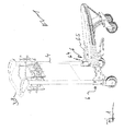
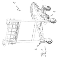
- the invention relates to a stackable transport vehicle 1, 1 'with a chassis 2, which is equipped with upward-striving bars 4, which carry a sliding device 3. Furthermore, the chassis 2 has a storage area 5 for goods, luggage and the like. The storage area 5 and the spars 4 lead into node pieces 6. For this purpose, each node piece 6 has a fastening area 6.4 for supporting a spar 4 and a further fastening area 6.5 for supporting a strut of the storage area 5.
- the knot piece 6 is designed in several parts; it is formed from at least two components, an outer component 6.1 and a middle component 6.2 "or else two outer components 6.1 and 6.3, and a middle component 6.2 or 6.2 '.
- the node piece 6 is formed from at least two components.
- the node piece 6 has an outer component 6.1 and a middle component 6.2 ".
- the node piece 6 of two outer components 6.1 and 6.3, and a central component 6.2 or 6.2 ' is formed.
- FIGS. 1 to 4 . 6 and 7 show such a trolley 1, 1 '.
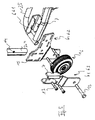
- a node piece 6 shown which is formed of three components 6.1, 6.2 or 6.2 'and 6.3.
- FIG. 10 shows a further variant of a middle component 6.2 ".
- node piece 6 is shown in each case.
- the node piece 6 is formed of three components, two outer 6.1, 6.3 and a middle 6.2 or 6.2 '.
- the components 6.1, 6.2 or 6.2 'and 6.3 are plugged into each other.
- the two outer components 6.1 and 6.3 For this purpose, they are provided with toothings 7, which engage in the middle component 6.2 or 6.2 'and connect the components 6.1, 6.2 or 6.2' and 6.3 with one another.
- Each trolley 1, 1 ' is preferably provided with an actuatable by the sliding device 3 brake device 8.
- the brake device 8 is equipped with two located in the bars 4 brake rods 9, at the lower end in each case one on a rear wheel of the carriage 1, 1 'acting brake shoe 10 is arranged.
- FIGS. 6 and 7 illustrated dolly 1 ' is equipped with a brake release device 11. Moreover, in such a car 1 ', a trigger part 12 is provided.
- the brake release device 11 and the release part 12 are components of the middle part 6.2 ', 6.1 "It has proven to be expedient that the middle part 6.2' and the brake release device 11 are formed from one part and that the trigger part 12 is attached to the middle part 6.2 '.
- the outer part 6.1 and the middle part 6.2 or 6.2 ' are connected together after one end of the storage area 5 has been placed in the outer part 6.1.
- the shape of the outer part 6.1 is thus adapted to the shape of the struts of the storage area 5.
- the outer part 6.1 has a rectangular cross section, wherein two of the side walls are provided with the teeth 7. These teeth 7 are formed by extended overhangs of the two side walls. They engage in the openings 15 of the middle part 6.2 or 6.2 'a.
- the components 6.1 and 6.2, 6.2 ', 6.2 "thus form a fastening region 6.5 for the storage area 5 and a mounting portion 6.4 for the spar 4. A simple arrangement of the spar 4 and storage area 5 is thus ensured.
- the length and the height of the outer part 6.1 are dependent on the cross section of the struts of the storage area. 5
- a respective rear roller 16 is mounted on the middle part 6.2 or 6.2 '. This is done with the aid of the outer part 6.3 and a securing means 13. At the same time as the spar 4, which has a brake rod 9 in its interior, the roller 16 is secured to the components 6.2 and 6.2 'and 6.3.
- the components 6.1, 6.2, 6.2 ', 6.2 "as well as 6.3 can be made of die-cast aluminum or zinc, or they can be laser-cut sheet metal parts or stamped parts.
- additional securing means 13 are used, which additionally secure the knot piece 6 on the chassis 2.
- additional securing means 13 For receiving the additional securing means 13, both the components 6.1, 6.2, 6.2 ', 6.2 "and 6.3 as well as each of the spar 4 and at the appropriate location of the storage area 5 holes 14.
- the outer component 6.3 is arranged largely perpendicular to the middle component 6.2, 6.2 'and engages in the upper half of the middle component 6.2, 6.2' a.
- the outer components 6.1 and 6.3 For safe engagement of the outer components 6.1 and 6.3 have these teeth 7. A number of four teeth 7 per component 6.1, 6.3 has proven to be useful. For receiving the outer components 6.1, 6.3, the middle component 6.2, 6.2 'openings 15, so that the teeth 7 can engage in the openings 15. A number of eight openings 15, corresponding to the number of teeth 7 of both components 6.1 and 6.3, has proven to be useful.
- the middle part 6.2 is used, no further outer part 6.3 is necessary, and the middle part 6.2" also has openings 15. These take on the teeth 7 of the outer part 6.1. For this purpose, a number of four openings 15 are sufficient, which are arranged horizontally in the lower half of the middle part 6.2 ".
- the middle part 6.2" is formed in one piece, a triggering part 12 is formed.
- the brake release device 11 can, as in the other variant, be attached. Securing means 13 for the arrangement of the roller 16 or for additional security can be provided if necessary.
Landscapes
- Engineering & Computer Science (AREA)
- Chemical & Material Sciences (AREA)
- Combustion & Propulsion (AREA)
- Transportation (AREA)
- Mechanical Engineering (AREA)
- Handcart (AREA)
- Braking Arrangements (AREA)
Abstract
Description
- Die Erfindung betrifft einen stapelbaren Transportwagen mit den Merkmalen im Oberbegriff des Hauptanspruchs.
- Solche Transportwagen sind in Form von so genannten Gepäcktransportwagen aus dem Stand der Technik bekannt. Sie sind mit drei oder vier Rollen ausgestattet und weisen einen Abstellbereich in Form einer Ladeplattform auf. Ferner sind Holme vorgesehen, an denen eine Schiebeeinrichtung angeordnet ist. Als Verbindungsstücke von Abstellbereich und Holm sind Knotenstücke vorgesehen. Der Wagen kann ferner mit einer Bremsvorrichtung versehen sein, wobei die Bremsstangen in den zwei Holmen geführt sind und an ihrem unteren Ende einen Bremsschuh aufweisen. Die
EP 0 722 846 B1 zeigt beispielsweise einen solchen Wagen mit einer Bremsvorrichtung. Die Knotenstücke bilden an dieser Stelle Raum für das geschützte Anordnen der unteren Enden der Bremsstangen, die mit dem Bremsschuh versehen sind, welcher jeweils auf die hinteren Rollen des Wagens wirkt. Wird eine Reihe solcher gestapelter Wagen bewegt, ist es notwendig, dass die hinteren Rollen eines Wagens angehoben sind, denn die Bremse wirkt auf die Rollen, solange sie nicht durch Herunterdrücken der Schiebeeinrichtung gelöst wird. - In einer weiterführenden Variante eines Wagens, wie z.B. in der
EP 1 590 224 B1 beschrieben, ist die Bremsvorrichtung zusätzlich mit einer Bremslöseeinrichtung, die mit dem Bremsschuh oder direkt mit der Bremsstange zusammenwirkt, und einem Auslöseteil unterhalb der Ladeplattform ausgestattet. In gestapeltem Zustand wird die Bremse durch Einwirken des Auslöseteils auf die Bremslöseeinrichtung gelöst. Dadurch kann eine Reihe an gestapelten Wagen auf einfache Art transportiert werden. - Darüber hinaus ist aus dem Stand der Technik und insbesondere der
DE 195 060 847 A1 bekannt, dass ein Knotenstück eines solchen Transportwagens z.B. aus zwei Halbschalen gebildet ist. Als Material für das Herstellen solcher Halbschalen als Spritzgussformteil hat sich ein Leichtmetall, wie Aluminium, oder auch ein Kunststoff als sinnvoll erwiesen. Die Holme und auch die Ladeplattform können auf einfache Art in das Knotenstück gesteckt werden und dann ggf. mittels einer zusätzlichen Schraube, mittels einer Klebung oder bei geeigneter Materialauswahl auch durch Schrumpfung gesichert werden. Bei der Verwendung solcher Halbschalen und dem einfachen Ineinanderstecken der Bauteile kann auf ein Zusammenschweißen der Bauteile verzichtet werden. - Die Aufgabe der vorliegenden Erfindung liegt nun darin, einen Transportwagen mit einem verbesserten Knotenstück aufzuzeigen, das zudem bei den beiden oben beschriebenen Wagentypen eingesetzt werden kann.
- Die Erfindung löst die Aufgabe mit den Merkmalen im Hauptanspruch. Weitere vorteilhafte Ausführungen sind in den Unteransprüchen beschrieben.
- Die Bauteile können auf einfache Art und Weise zusammengefügt werden. Hierfür weisen die äußeren Teile Verzahnungen auf, die in die Öffnungen des mittleren Bauteils eingreifen können.
- Weitere Befestigungen sind nicht notwendig. Auf aufwendiges Schweißen kann verzichtet werden.
- Je nach Wahl des mittleren Bauteils kann ein solches, aus mehreren Bauteilen gebildetes Knotenstück, sowohl für Wagen mit aber auch ohne Bremslöseeinrichtung verwendet werden.
- Die Erfindung wird anhand von zwei Ausführungsbeispielen näher erläutert. Es zeigt
- Fig. 1
- einen ersten Transportwagen mit einem erfindungsgemäßen Knotenstück in perspektivischer Ansicht,
- Fig. 2
- denselben Transportwagen in einer weiteren perspektivischen Ansicht,
- Fig. 3
- denselben Transportwagen in Rückansicht,
- Fig. 4
- denselben Transportwagen in Draufsicht,
- Fig. 5
- ein Knotenstück des Transportwagens in Explosionsdarstellung,
- Fig. 6
- einen zweiten Transportwagen mit einem erfindungsgemäßen Knotenstück in perspektivischer Ansicht,
- Fig. 7
- denselben Transportwagen in einer weiteren perspektivischen Ansicht,
- Fig. 8
- ein Knotenstück des Transportwagens in Explosionsdarstellung,
- Fig. 9
- das Knotenstück des Transportwagens in einer weiteren Explosionsdarstellung, sowie
- Fig. 10
- eine weitere Variante eines mittleren Bauteils des Knotenstücks in Explosionsdarstellung.
- Die Erfindung betrifft einen stapelbaren Transportwagen 1, 1' mit einem Fahrgestell 2, das mit nach oben strebenden Holmen 4 ausgestattet ist, die eine Schiebeeinrichtung 3 tragen. Ferner weist das Fahrgestell 2 einen Abstellbereich 5 für Ware, Gepäck und dergleichen auf. Der Abstellbereich 5 und die Holme 4 führen in Knotenstücke 6. Hierfür weist jedes Knotenstück 6 einen Befestigungsbereich 6.4 zum Tragen eines Holmes 4 und einen weiteren Befestigungsbereich 6.5 zum Tragen einer Strebe des Abstellbereichs 5 auf.
- Das Knotenstück 6 ist hierfür mehrteilig ausgeführt, es ist aus mindestens zwei Bauteilen, einem äußeren Bauteil 6.1 und einem mittleren Bauteil 6.2" oder aber aus zwei äußeren Bauteilen 6.1 und 6.3, sowie einem mittleren Bauteil 6.2 oder 6.2' gebildet.
- Das Knotenstück 6 ist aus mindestens zwei Bauteilen gebildet.
- In einer Variante weist das Knotenstück 6 ein äußeres Bauteil 6.1 und ein mittleres Bauteil 6.2" auf.
- In einer anderen Variante ist das Knotenstück 6 aus zwei äußeren Bauteilen 6.1 und 6.3, sowie einem mittleren Bauteil 6.2 bzw. 6.2' gebildet.
- Die Bauteile 6.1, 6.2 und 6.3 bzw. 6.1, 6.2' und 6.3 oder 6.1 und 6.2" werden ineinander gesteckt. Hierfür sind die äußeren Bauteile 6.1 und 6.3 mit Verzahnungen 7 ausgestattet, die in das mittlere Bauteil 6.2, 6.2' oder 6.2" eingreifen.
- Die
Figuren 1 bis 4 ,6 und 7 zeigen einen solchen Transportwagen 1, 1'. In denFiguren 1 bis 9 ist ein Knotenstück 6 dargestellt, das aus drei Bauteilen 6.1, 6.2 oder 6.2' und 6.3 gebildet ist. -
Figur 10 zeigt eine weitere Variante eines mittleren Bauteils 6.2". - Unabhängig von der Anzahl der Bauteile werden diese ineinander gesteckt.
- In den
Figuren 5 und8 bzw. 9 ist jeweils ein solches Knotenstück 6 dargestellt. Das Knotenstück 6 ist aus drei Bauteilen, zwei äußeren 6.1, 6.3 und einem mittleren 6.2 bzw. 6.2' gebildet. Die Bauteile 6.1, 6.2 bzw. 6.2' und 6.3 werden ineinander gesteckt. Die beiden äußeren Bauteile 6.1 und 6.3 sind hierfür mit Verzahnungen 7 ausgestattet, die in das mittlere Bauteil 6.2 bzw. 6.2' eingreifen und die Bauteile 6.1, 6.2 bzw. 6.2' und 6.3 miteinander verbinden. - Jeder Transportwagen 1, 1' ist vorzugsweise mit einer durch die Schiebeeinrichtung 3 betätigbaren Bremsvorrichtung 8 versehen. Die Bremsvorrichtung 8 ist mit zwei in den Holmen 4 befindlichen Bremsstangen 9 ausgestattet, an deren unterem Ende jeweils ein auf ein Hinterrad des Wagens 1, 1' einwirkender Bremsschuh 10 angeordnet ist.
- Der in den
Figuren 6 und7 dargestellte Transportwagen 1' ist mit einer Bremslösevorrichtung 11 ausgestattet. Darüber hinaus ist bei einem solchen Wagen 1' ein Auslöseteil 12 vorgesehen. - Wie aus den Darstellungen 8 und 9 hervorgeht, sind die Bremslösevorrichtung 11 und das Auslöseteil 12 Bestandteile des mittleren Teiles 6.2', 6.1". Es hat sich als sinnvoll erwiesen, dass das mittlere Teil 6.2' und die Bremslösevorrichtung 11 aus einem Teil gebildet sind und dass das Auslöseteil 12 an dem mittleren Teil 6.2' angebracht wird.
- Hinsichtlich der Montage werden zunächst das äußere Teil 6.1 und das mittlere Teil 6.2 bzw. 6.2' miteinander verbunden, nachdem ein Ende des Abstellbereichs 5 in das äußere Teil 6.1 gelegt wurde. Die Form des äußeren Teils 6.1 ist somit angepasst an die Form der Verstrebungen des Abstellbereichs 5. In den Darstellungen weist das äußere Teil 6.1 einen rechteckigen Querschnitt auf, wobei zwei der Seitenwände mit den Verzahnungen 7 versehen sind. Diese Verzahnungen 7 sind durch verlängerte Überhänge der beiden Seitenwände gebildet. Sie greifen in die Öffnungen 15 des mittleren Teils 6.2 bzw. 6.2' ein. Die Bauteile 6.1 und 6.2, 6.2', 6.2" bilden somit einen Befestigungsbereich 6.5 für den Abstellbereich 5 und einen Befestigungsbereich 6.4 für den Holm 4. Ein einfaches Anordnen von Holm 4 und Abstellbereich 5 ist somit gewährleistet.
- Die Länge und die Höhe des äußeren Teils 6.1 sind abhängig von dem Querschnitt der Verstrebungen des Abstellbereichs 5.
- Dann wird jeweils eine hintere Rolle 16 an dem mittleren Teil 6.2 bzw. 6.2' montiert. Dies geschieht unter Zuhilfenahme des äußeren Teils 6.3 und einem Sicherungsmittel 13. Gleichzeitig wie der Holm 4, der in seinem Inneren eine Bremsstange 9 aufweist, wird die Rolle 16 an den Bauteilen 6.2 bzw. 6.2' und 6.3 gesichert.
- Die Bauteile 6.1, 6.2, 6.2', 6.2" sowie 6.3 können aus einem Aluminium-oder Zink-Druckguss hergestellt werden. Auch können es gelaserte Blechteile oder Prägeteile sein.
- Es kann sich unter Umständen als sinnvoll erweisen, dass zusätzliche Sicherungsmittel 13 eingesetzt werden, die das Knotenstück 6 am Fahrgestell 2 zusätzlich sichern. Für die Aufnahme der zusätzlichen Sicherungsmittel 13 weisen sowohl die Bauteile 6.1, 6.2, 6.2', 6.2" und 6.3 als auch jeweils der Holm 4 und an entsprechender Stelle der Abstellbereich 5 Bohrungen 14 auf.
- Aus den
Figuren 5 ,8 und9 geht hervor, dass das äußere Bauteil 6.1 weitestgehend waagrecht am mittleren Bauteil 6.2, 6.2' angeordnet ist und in der unteren Hälfte des mittleren Bauteils 6.2, 6.2' eingreift. - Das äußere Bauteil 6.3 ist weitestgehend senkrecht am mittleren Bauteil 6.2, 6.2' angeordnet und greift in der oberen Hälfte des mittleren Bauteils 6.2, 6.2' ein.
- Zum sicheren Eingreifen der äußeren Bauteile 6.1 und 6.3 weisen diese Verzahnungen 7 auf. Eine Anzahl von vier Verzahnungen 7 pro Bauteil 6.1, 6.3 hat sich als sinnvoll erwiesen. Zur Aufnahme der äußeren Bauteile 6.1, 6.3 weist das mittlere Bauteil 6.2, 6.2' Öffnungen 15 auf, so dass die Verzahnungen 7 in die Öffnungen 15 eingreifen können. Eine Anzahl von acht Öffnungen 15, entsprechend der Anzahl der Verzahnungen 7 beider Bauteile 6.1 und 6.3, hat sich als sinnvoll erwiesen.
- Wie aus
Figur 10 hervorgeht, ist bei Verwendung des mittleren Teiles 6.2" kein weiteres äußeres Teil 6.3 notwendig. Auch das mittlere Teil 6.2" weist Öffnungen 15 auf. Diese nehmen die Verzahnungen 7 des äußeren Teils 6.1 auf. Hierfür reicht eine Anzahl von vier Öffnungen 15 aus, die in der unteren Hälfte des mittleren Teiles 6.2" waagrecht angeordnet sind. Das mittlere Teil 6.2" ist einteilig gebildet, ein Auslöseteil 12 angeformt. Die Bremslösevorrichtung 11 kann, wie bei der anderen Variante, angebracht werden. Sicherungsmittel 13 für die Anordnung der Rolle 16 oder zur zusätzlichen Sicherung können bei Bedarf vorgesehen werden. -
1, 1' Transportwagen 2 Fahrgestell 3 Schiebeeinrichtung 4 Holm 5 Abstellbereich 6 Knotenstück 6.1 äußeres Bauteil / Teil 6.2, 6.2', 6.2" mittleres Bauteil / Teil 6.3 äußeres Bauteil / Teil 6.4 Befestigungsbereich (Holm) 6.5 Befestigungsbereich (Abstellbereich) 7 Verzahnung 8 Bremsvorrichtung 9 Bremsstange 10 Bremsschuh 11 Bremslösevorrichtung 12 Auslöseteil 13 Sicherungsmittel 14 Bohrungen 15 Öffnungen 16 Rollen
Claims (10)
- Transportwagen (1, 1') mit einem Fahrgestell (2), wobei das Fahrgestell (2) mit nach oben strebenden Holmen (4) ausgestattet ist, die eine Schiebeeinrichtung (3) tragen, und wobei das Fahrgestell (2) einen Abstellbereich (5) für Ware, Gepäck und dergleichen aufweist, ferner führen Abstellbereich (5) und Holme (4) in Knotenstücke (6), wobei jedes Knotenstück (6) einen Befestigungsbereich (6.4) zum Tragen eines Holmes (4) und einen weiteren Befestigungsbereich (6.5) zum Tragen des Abstellbereichs (5) aufweist, wobei das Knotenstück (6) mehrteilig ausgeführt ist, dadurch gekennzeichnet, dass das Knotenstück (6) aus mindestens zwei Bauteilen, einem äußeren Bauteil (6.1) und einem mittleren Bauteil (6.2") oder aber aus zwei äußeren Bauteilen (6.1) und (6.3), sowie einem mittleren Bauteil (6.2) bzw. (6.2') gebildet ist, wobei die Bauteile (6.1), (6.2) und (6.3) oder (6.1), (6.2') und (6.3) oder (6.1) und (6.2") ineinander gesteckt werden, und wobei die äußeren Bauteile (6.1) und (6.3) mit Verzahnungen (7) ausgestattet sind, die in das mittlere Bauteil (6.2, 6.2', 6.2") eingreifen.
- Transportwagen nach Anspruch 1, dadurch gekennzeichnet, dass eine durch die Schiebeeinrichtung (3) betätigbare Bremsvorrichtung (8) vorgesehen ist, die mit zwei in den Holmen (4) befindlichen Bremsstangen (9) ausgestattet ist, an deren unterem Ende jeweils ein auf ein Hinterrad einwirkender Bremsschuh (10) angeordnet ist.
- Transportwagen nach Anspruch 2, dadurch gekennzeichnet, dass eine Bremslösevorrichtung (11) vorgesehen ist.
- Transportwagen nach einem der vorhergehenden Ansprüche, dadurch gekennzeichnet, dass ein Auslöseteil (12) vorgesehen ist.
- Transportwagen nach einem der vorhergehenden Ansprüche, dadurch gekennzeichnet, dass die Bremslösevorrichtung (11) und das Auslöseteil (12) Bestandteile des mittleren Bauteils (6.2', 6.2") sind.
- Transportwagen nach einem der vorhergehenden Ansprüche, dadurch gekennzeichnet, dass zusätzliche Sicherungsmittel (13) eingesetzt werden, die das Knotenstück (6) am Fahrgestell (2) zusätzlich sichern.
- Transportwagen nach einem der vorhergehenden Ansprüche, dadurch gekennzeichnet, dass zur Aufnahme der zusätzlichen Sicherungsmittel (13) sowohl die Bauteile (6.1, 6.2, 6.2', 6.2", 6.3) als auch jeweils der Holm (4) und der Abstellbereich (5) an entsprechender Stelle Bohrungen (14) aufweisen.
- Transportwagen nach einem der vorhergehenden Ansprüche, dadurch gekennzeichnet, dass das äußere Bauteil (6.1) weitestgehend waagrecht am mittleren Bauteil (6.2, 6.2') angeordnet ist und in der unteren Hälfe des mittleren Bauteils (6.2, 6.2') eingreift.
- Transportwagen nach einem der vorhergehenden Ansprüche, dadurch gekennzeichnet, dass das äußere Bauteil (6.3) weitestgehend senkrecht am mittleren Bauteil (6.2, 6.2') angeordnet ist und in der oberen Hälfte des mittleren Bauteils (6.2, 6.2') eingreift.
- Transportwagen nach einem der vorhergehenden Ansprüche, dadurch gekennzeichnet, dass die äußeren Bauteile (6.1, 6.3) jeweils vier Verzahnungen (7) und das mittlere Bauteil (6.2, 6.2') acht Öffnungen (15) aufweisen, so dass die Verzahnungen (7) in die Öffnungen (15) eingreifen können.
Priority Applications (1)
| Application Number | Priority Date | Filing Date | Title |
|---|---|---|---|
| PL13161612T PL2650192T3 (pl) | 2012-04-11 | 2013-03-28 | Wózek transportowy |
Applications Claiming Priority (1)
| Application Number | Priority Date | Filing Date | Title |
|---|---|---|---|
| DE102012103090.1A DE102012103090B4 (de) | 2012-04-11 | 2012-04-11 | Transportwagen |
Publications (3)
| Publication Number | Publication Date |
|---|---|
| EP2650192A2 true EP2650192A2 (de) | 2013-10-16 |
| EP2650192A3 EP2650192A3 (de) | 2017-01-04 |
| EP2650192B1 EP2650192B1 (de) | 2018-06-27 |
Family
ID=48013836
Family Applications (1)
| Application Number | Title | Priority Date | Filing Date |
|---|---|---|---|
| EP13161612.0A Not-in-force EP2650192B1 (de) | 2012-04-11 | 2013-03-28 | Transportwagen |
Country Status (5)
| Country | Link |
|---|---|
| EP (1) | EP2650192B1 (de) |
| CN (1) | CN103373381B (de) |
| DE (1) | DE102012103090B4 (de) |
| ES (1) | ES2681444T3 (de) |
| PL (1) | PL2650192T3 (de) |
Cited By (1)
| Publication number | Priority date | Publication date | Assignee | Title |
|---|---|---|---|---|
| WO2021009245A1 (de) * | 2019-07-17 | 2021-01-21 | Wanzl GmbH & Co. KGaA | Transportwagen und korb |
Families Citing this family (1)
| Publication number | Priority date | Publication date | Assignee | Title |
|---|---|---|---|---|
| DE102021210439A1 (de) | 2021-09-20 | 2023-04-06 | Psa Automobiles Sa | Lastentransportfahrzeug und Fahrzeugverbund |
Citations (3)
| Publication number | Priority date | Publication date | Assignee | Title |
|---|---|---|---|---|
| DE19506847A1 (de) | 1995-02-28 | 1996-09-05 | Expresso Deutschland | Schubgepäckwagen |
| EP0722846B1 (de) | 1995-01-18 | 1998-02-04 | Wanzl GmbH & Co. Entwicklungs-KG | Transportwagen |
| EP1590224B1 (de) | 2003-02-06 | 2006-06-21 | Wanzl Metallwarenfabrik GmbH | Von hand bewegbarer transportwagen |
Family Cites Families (8)
| Publication number | Priority date | Publication date | Assignee | Title |
|---|---|---|---|---|
| DE8804327U1 (de) * | 1988-03-30 | 1988-09-08 | Brüder Siegel GmbH & Co KG Draht- und Metallwarenfabrik, 8874 Leipheim | Einkaufswagen für Selbstbedienungsgeschäfte, Baumärkte und dgl. |
| DE4315399A1 (de) * | 1993-05-08 | 1994-11-10 | Wanzl Entwicklung Gmbh | Von Hand bewegbarer Transportwagen, insbesondere Einkaufswagen |
| DE29602974U1 (de) * | 1996-02-20 | 1997-06-19 | Expresso Deutschland Transportgeräte GmbH, 34123 Kassel | Schubgepäckwagen |
| DE19849843A1 (de) * | 1998-10-29 | 2000-05-04 | Wanzl Metallwarenfabrik Kg | Fahrrahmen |
| DE10039715B4 (de) * | 2000-08-14 | 2011-10-13 | EXPRESSO DEUTSCHLAND TRANSPORTGERäTE GMBH | Schubgepäckwagen |
| JP3472757B2 (ja) * | 2000-10-06 | 2003-12-02 | 株式会社佐野車輛製作所 | 搬送台車 |
| DE102008045144A1 (de) * | 2008-09-01 | 2010-03-04 | Wanzl Metallwarenfabrik Gmbh | Transportwagen |
| WO2011017818A1 (zh) * | 2009-08-11 | 2011-02-17 | Jian Shikun | 一种四轮平板车的脚轮定位收合装置 |
-
2012
- 2012-04-11 DE DE102012103090.1A patent/DE102012103090B4/de not_active Expired - Fee Related
-
2013
- 2013-03-28 ES ES13161612.0T patent/ES2681444T3/es active Active
- 2013-03-28 PL PL13161612T patent/PL2650192T3/pl unknown
- 2013-03-28 EP EP13161612.0A patent/EP2650192B1/de not_active Not-in-force
- 2013-04-10 CN CN201310195113.7A patent/CN103373381B/zh not_active Expired - Fee Related
Patent Citations (3)
| Publication number | Priority date | Publication date | Assignee | Title |
|---|---|---|---|---|
| EP0722846B1 (de) | 1995-01-18 | 1998-02-04 | Wanzl GmbH & Co. Entwicklungs-KG | Transportwagen |
| DE19506847A1 (de) | 1995-02-28 | 1996-09-05 | Expresso Deutschland | Schubgepäckwagen |
| EP1590224B1 (de) | 2003-02-06 | 2006-06-21 | Wanzl Metallwarenfabrik GmbH | Von hand bewegbarer transportwagen |
Cited By (3)
| Publication number | Priority date | Publication date | Assignee | Title |
|---|---|---|---|---|
| WO2021009245A1 (de) * | 2019-07-17 | 2021-01-21 | Wanzl GmbH & Co. KGaA | Transportwagen und korb |
| CN114423666A (zh) * | 2019-07-17 | 2022-04-29 | 旺众有限及股份两合公司 | 运输车和篮子 |
| CN114423666B (zh) * | 2019-07-17 | 2025-05-16 | 旺众有限及股份两合公司 | 运输车和篮子 |
Also Published As
| Publication number | Publication date |
|---|---|
| EP2650192B1 (de) | 2018-06-27 |
| CN103373381B (zh) | 2018-09-04 |
| CN103373381A (zh) | 2013-10-30 |
| EP2650192A3 (de) | 2017-01-04 |
| ES2681444T3 (es) | 2018-09-13 |
| DE102012103090A1 (de) | 2013-10-17 |
| DE102012103090B4 (de) | 2018-04-26 |
| PL2650192T3 (pl) | 2018-12-31 |
Similar Documents
| Publication | Publication Date | Title |
|---|---|---|
| EP3371031B1 (de) | Transportwagen | |
| EP3141455B1 (de) | Vorrichtung zum transport von stückgütern | |
| EP2994361B1 (de) | Fahrbares transportgerät | |
| EP2004470A1 (de) | Einkaufswagen | |
| WO2017152893A1 (de) | Von hand bewegbares transportgerät | |
| DE102012001503B4 (de) | Palette zum Transportieren von Rollwagen | |
| DE10338724A1 (de) | Heckträger für ein Kraftfahrzeug | |
| DE102010027889A1 (de) | Mobile Scherenhebebühne | |
| DE102011012124A1 (de) | Bodengruppe für eine Mehrzahl von Bauvarianten einer Karosserie eines Personenkraftwagens, insbesondere mit Heckantriebsaggregat | |
| EP2650192B1 (de) | Transportwagen | |
| EP2703216B1 (de) | Nutzfahrzeugaufbau mit Ladungssicherung für den Doppelstockbetrieb | |
| DE202011003780U1 (de) | Einkaufswagen | |
| EP2835337B1 (de) | Flurförderzeug mit einem Antriebsteil und einem Lastteil | |
| EP3398810A1 (de) | Kompaktheck an nutzfahrzeugen mit ausfahrbarem heck | |
| DE202015105816U1 (de) | Transportwagen | |
| DE102008025440B4 (de) | Einstecklatte für einen Aufbau eines Transportfahrzeugs, Aufbau für die Ladefläche eines Transportfahrzeugs, eines Lastkraftwagens, eines Aufliegers oder Anhängers für einen Lastkraftwagen mit einer solchen Einstecklatte und Transportfahrzeug, Lastkraftwagen, Auflieger oder Anhänger für einen Lastkraftwagen mit einer Ladefläche und einem solchen Aufbau. | |
| AT509552B1 (de) | Gestell | |
| EP1587728B1 (de) | Runge mit integrierter vorrichtung zur ladungssicherung, insb. für transportfahrzeuge mit planenaufbauten | |
| DE202009003533U1 (de) | Nutzfahrzeug | |
| DE102008064332A1 (de) | Transportvorrichtung | |
| DE8902179U1 (de) | Einkaufswagen mit abnehmbaren Körben | |
| EP0722846B1 (de) | Transportwagen | |
| EP2810849A2 (de) | Transportwagen | |
| DE10303058B4 (de) | Runge mit integrierter Vorrichtung zur Ladungssicherung, insbesondere für Transportfahrzeuge mit Planenaufbauten | |
| DE202015009019U1 (de) | Transportwagen |
Legal Events
| Date | Code | Title | Description |
|---|---|---|---|
| PUAI | Public reference made under article 153(3) epc to a published international application that has entered the european phase |
Free format text: ORIGINAL CODE: 0009012 |
|
| AK | Designated contracting states |
Kind code of ref document: A2 Designated state(s): AL AT BE BG CH CY CZ DE DK EE ES FI FR GB GR HR HU IE IS IT LI LT LU LV MC MK MT NL NO PL PT RO RS SE SI SK SM TR |
|
| AX | Request for extension of the european patent |
Extension state: BA ME |
|
| RAP1 | Party data changed (applicant data changed or rights of an application transferred) |
Owner name: WANZL METALLWARENFABRIK GMBH |
|
| PUAL | Search report despatched |
Free format text: ORIGINAL CODE: 0009013 |
|
| AK | Designated contracting states |
Kind code of ref document: A3 Designated state(s): AL AT BE BG CH CY CZ DE DK EE ES FI FR GB GR HR HU IE IS IT LI LT LU LV MC MK MT NL NO PL PT RO RS SE SI SK SM TR |
|
| AX | Request for extension of the european patent |
Extension state: BA ME |
|
| RIC1 | Information provided on ipc code assigned before grant |
Ipc: B62B 3/14 20060101AFI20161125BHEP Ipc: B62B 5/04 20060101ALI20161125BHEP |
|
| STAA | Information on the status of an ep patent application or granted ep patent |
Free format text: STATUS: REQUEST FOR EXAMINATION WAS MADE |
|
| 17P | Request for examination filed |
Effective date: 20170704 |
|
| RBV | Designated contracting states (corrected) |
Designated state(s): AL AT BE BG CH CY CZ DE DK EE ES FI FR GB GR HR HU IE IS IT LI LT LU LV MC MK MT NL NO PL PT RO RS SE SI SK SM TR |
|
| GRAP | Despatch of communication of intention to grant a patent |
Free format text: ORIGINAL CODE: EPIDOSNIGR1 |
|
| STAA | Information on the status of an ep patent application or granted ep patent |
Free format text: STATUS: GRANT OF PATENT IS INTENDED |
|
| INTG | Intention to grant announced |
Effective date: 20180215 |
|
| GRAS | Grant fee paid |
Free format text: ORIGINAL CODE: EPIDOSNIGR3 |
|
| GRAA | (expected) grant |
Free format text: ORIGINAL CODE: 0009210 |
|
| STAA | Information on the status of an ep patent application or granted ep patent |
Free format text: STATUS: THE PATENT HAS BEEN GRANTED |
|
| AK | Designated contracting states |
Kind code of ref document: B1 Designated state(s): AL AT BE BG CH CY CZ DE DK EE ES FI FR GB GR HR HU IE IS IT LI LT LU LV MC MK MT NL NO PL PT RO RS SE SI SK SM TR |
|
| REG | Reference to a national code |
Ref country code: GB Ref legal event code: FG4D Free format text: NOT ENGLISH |
|
| REG | Reference to a national code |
Ref country code: AT Ref legal event code: REF Ref document number: 1012033 Country of ref document: AT Kind code of ref document: T Effective date: 20180715 |
|
| REG | Reference to a national code |
Ref country code: IE Ref legal event code: FG4D Free format text: LANGUAGE OF EP DOCUMENT: GERMAN |
|
| REG | Reference to a national code |
Ref country code: DE Ref legal event code: R096 Ref document number: 502013010458 Country of ref document: DE |
|
| REG | Reference to a national code |
Ref country code: ES Ref legal event code: FG2A Ref document number: 2681444 Country of ref document: ES Kind code of ref document: T3 Effective date: 20180913 |
|
| PG25 | Lapsed in a contracting state [announced via postgrant information from national office to epo] |
Ref country code: BG Free format text: LAPSE BECAUSE OF FAILURE TO SUBMIT A TRANSLATION OF THE DESCRIPTION OR TO PAY THE FEE WITHIN THE PRESCRIBED TIME-LIMIT Effective date: 20180927 Ref country code: FI Free format text: LAPSE BECAUSE OF FAILURE TO SUBMIT A TRANSLATION OF THE DESCRIPTION OR TO PAY THE FEE WITHIN THE PRESCRIBED TIME-LIMIT Effective date: 20180627 Ref country code: LT Free format text: LAPSE BECAUSE OF FAILURE TO SUBMIT A TRANSLATION OF THE DESCRIPTION OR TO PAY THE FEE WITHIN THE PRESCRIBED TIME-LIMIT Effective date: 20180627 Ref country code: NO Free format text: LAPSE BECAUSE OF FAILURE TO SUBMIT A TRANSLATION OF THE DESCRIPTION OR TO PAY THE FEE WITHIN THE PRESCRIBED TIME-LIMIT Effective date: 20180927 Ref country code: SE Free format text: LAPSE BECAUSE OF FAILURE TO SUBMIT A TRANSLATION OF THE DESCRIPTION OR TO PAY THE FEE WITHIN THE PRESCRIBED TIME-LIMIT Effective date: 20180627 |
|
| REG | Reference to a national code |
Ref country code: NL Ref legal event code: MP Effective date: 20180627 |
|
| REG | Reference to a national code |
Ref country code: LT Ref legal event code: MG4D |
|
| PG25 | Lapsed in a contracting state [announced via postgrant information from national office to epo] |
Ref country code: LV Free format text: LAPSE BECAUSE OF FAILURE TO SUBMIT A TRANSLATION OF THE DESCRIPTION OR TO PAY THE FEE WITHIN THE PRESCRIBED TIME-LIMIT Effective date: 20180627 Ref country code: RS Free format text: LAPSE BECAUSE OF FAILURE TO SUBMIT A TRANSLATION OF THE DESCRIPTION OR TO PAY THE FEE WITHIN THE PRESCRIBED TIME-LIMIT Effective date: 20180627 Ref country code: HR Free format text: LAPSE BECAUSE OF FAILURE TO SUBMIT A TRANSLATION OF THE DESCRIPTION OR TO PAY THE FEE WITHIN THE PRESCRIBED TIME-LIMIT Effective date: 20180627 Ref country code: GR Free format text: LAPSE BECAUSE OF FAILURE TO SUBMIT A TRANSLATION OF THE DESCRIPTION OR TO PAY THE FEE WITHIN THE PRESCRIBED TIME-LIMIT Effective date: 20180928 |
|
| PG25 | Lapsed in a contracting state [announced via postgrant information from national office to epo] |
Ref country code: NL Free format text: LAPSE BECAUSE OF FAILURE TO SUBMIT A TRANSLATION OF THE DESCRIPTION OR TO PAY THE FEE WITHIN THE PRESCRIBED TIME-LIMIT Effective date: 20180627 |
|
| PG25 | Lapsed in a contracting state [announced via postgrant information from national office to epo] |
Ref country code: EE Free format text: LAPSE BECAUSE OF FAILURE TO SUBMIT A TRANSLATION OF THE DESCRIPTION OR TO PAY THE FEE WITHIN THE PRESCRIBED TIME-LIMIT Effective date: 20180627 Ref country code: SK Free format text: LAPSE BECAUSE OF FAILURE TO SUBMIT A TRANSLATION OF THE DESCRIPTION OR TO PAY THE FEE WITHIN THE PRESCRIBED TIME-LIMIT Effective date: 20180627 Ref country code: RO Free format text: LAPSE BECAUSE OF FAILURE TO SUBMIT A TRANSLATION OF THE DESCRIPTION OR TO PAY THE FEE WITHIN THE PRESCRIBED TIME-LIMIT Effective date: 20180627 Ref country code: IS Free format text: LAPSE BECAUSE OF FAILURE TO SUBMIT A TRANSLATION OF THE DESCRIPTION OR TO PAY THE FEE WITHIN THE PRESCRIBED TIME-LIMIT Effective date: 20181027 |
|
| PG25 | Lapsed in a contracting state [announced via postgrant information from national office to epo] |
Ref country code: SM Free format text: LAPSE BECAUSE OF FAILURE TO SUBMIT A TRANSLATION OF THE DESCRIPTION OR TO PAY THE FEE WITHIN THE PRESCRIBED TIME-LIMIT Effective date: 20180627 Ref country code: IT Free format text: LAPSE BECAUSE OF FAILURE TO SUBMIT A TRANSLATION OF THE DESCRIPTION OR TO PAY THE FEE WITHIN THE PRESCRIBED TIME-LIMIT Effective date: 20180627 |
|
| REG | Reference to a national code |
Ref country code: DE Ref legal event code: R097 Ref document number: 502013010458 Country of ref document: DE |
|
| PLBE | No opposition filed within time limit |
Free format text: ORIGINAL CODE: 0009261 |
|
| STAA | Information on the status of an ep patent application or granted ep patent |
Free format text: STATUS: NO OPPOSITION FILED WITHIN TIME LIMIT |
|
| PG25 | Lapsed in a contracting state [announced via postgrant information from national office to epo] |
Ref country code: DK Free format text: LAPSE BECAUSE OF FAILURE TO SUBMIT A TRANSLATION OF THE DESCRIPTION OR TO PAY THE FEE WITHIN THE PRESCRIBED TIME-LIMIT Effective date: 20180627 |
|
| 26N | No opposition filed |
Effective date: 20190328 |
|
| PG25 | Lapsed in a contracting state [announced via postgrant information from national office to epo] |
Ref country code: SI Free format text: LAPSE BECAUSE OF FAILURE TO SUBMIT A TRANSLATION OF THE DESCRIPTION OR TO PAY THE FEE WITHIN THE PRESCRIBED TIME-LIMIT Effective date: 20180627 |
|
| PG25 | Lapsed in a contracting state [announced via postgrant information from national office to epo] |
Ref country code: MC Free format text: LAPSE BECAUSE OF FAILURE TO SUBMIT A TRANSLATION OF THE DESCRIPTION OR TO PAY THE FEE WITHIN THE PRESCRIBED TIME-LIMIT Effective date: 20180627 |
|
| REG | Reference to a national code |
Ref country code: CH Ref legal event code: PL |
|
| PG25 | Lapsed in a contracting state [announced via postgrant information from national office to epo] |
Ref country code: LU Free format text: LAPSE BECAUSE OF NON-PAYMENT OF DUE FEES Effective date: 20190328 Ref country code: AL Free format text: LAPSE BECAUSE OF FAILURE TO SUBMIT A TRANSLATION OF THE DESCRIPTION OR TO PAY THE FEE WITHIN THE PRESCRIBED TIME-LIMIT Effective date: 20180627 |
|
| REG | Reference to a national code |
Ref country code: BE Ref legal event code: MM Effective date: 20190331 |
|
| REG | Reference to a national code |
Ref country code: DE Ref legal event code: R081 Ref document number: 502013010458 Country of ref document: DE Owner name: WANZL GMBH & CO. KGAA, DE Free format text: FORMER OWNER: WANZL METALLWARENFABRIK GMBH, 89340 LEIPHEIM, DE |
|
| PG25 | Lapsed in a contracting state [announced via postgrant information from national office to epo] |
Ref country code: IE Free format text: LAPSE BECAUSE OF NON-PAYMENT OF DUE FEES Effective date: 20190328 Ref country code: LI Free format text: LAPSE BECAUSE OF NON-PAYMENT OF DUE FEES Effective date: 20190331 Ref country code: CH Free format text: LAPSE BECAUSE OF NON-PAYMENT OF DUE FEES Effective date: 20190331 |
|
| PG25 | Lapsed in a contracting state [announced via postgrant information from national office to epo] |
Ref country code: BE Free format text: LAPSE BECAUSE OF NON-PAYMENT OF DUE FEES Effective date: 20190331 |
|
| PG25 | Lapsed in a contracting state [announced via postgrant information from national office to epo] |
Ref country code: TR Free format text: LAPSE BECAUSE OF FAILURE TO SUBMIT A TRANSLATION OF THE DESCRIPTION OR TO PAY THE FEE WITHIN THE PRESCRIBED TIME-LIMIT Effective date: 20180627 |
|
| PG25 | Lapsed in a contracting state [announced via postgrant information from national office to epo] |
Ref country code: PT Free format text: LAPSE BECAUSE OF FAILURE TO SUBMIT A TRANSLATION OF THE DESCRIPTION OR TO PAY THE FEE WITHIN THE PRESCRIBED TIME-LIMIT Effective date: 20181029 Ref country code: MT Free format text: LAPSE BECAUSE OF FAILURE TO SUBMIT A TRANSLATION OF THE DESCRIPTION OR TO PAY THE FEE WITHIN THE PRESCRIBED TIME-LIMIT Effective date: 20180627 |
|
| REG | Reference to a national code |
Ref country code: AT Ref legal event code: MM01 Ref document number: 1012033 Country of ref document: AT Kind code of ref document: T Effective date: 20190328 |
|
| REG | Reference to a national code |
Ref country code: ES Ref legal event code: PC2A Owner name: WANZL GMBH & CO. KGAA Effective date: 20200916 |
|
| PG25 | Lapsed in a contracting state [announced via postgrant information from national office to epo] |
Ref country code: AT Free format text: LAPSE BECAUSE OF NON-PAYMENT OF DUE FEES Effective date: 20190328 |
|
| PG25 | Lapsed in a contracting state [announced via postgrant information from national office to epo] |
Ref country code: CY Free format text: LAPSE BECAUSE OF FAILURE TO SUBMIT A TRANSLATION OF THE DESCRIPTION OR TO PAY THE FEE WITHIN THE PRESCRIBED TIME-LIMIT Effective date: 20180627 |
|
| PG25 | Lapsed in a contracting state [announced via postgrant information from national office to epo] |
Ref country code: HU Free format text: LAPSE BECAUSE OF FAILURE TO SUBMIT A TRANSLATION OF THE DESCRIPTION OR TO PAY THE FEE WITHIN THE PRESCRIBED TIME-LIMIT; INVALID AB INITIO Effective date: 20130328 |
|
| PG25 | Lapsed in a contracting state [announced via postgrant information from national office to epo] |
Ref country code: MK Free format text: LAPSE BECAUSE OF FAILURE TO SUBMIT A TRANSLATION OF THE DESCRIPTION OR TO PAY THE FEE WITHIN THE PRESCRIBED TIME-LIMIT Effective date: 20180627 |
|
| PGFP | Annual fee paid to national office [announced via postgrant information from national office to epo] |
Ref country code: FR Payment date: 20230320 Year of fee payment: 11 Ref country code: CZ Payment date: 20230315 Year of fee payment: 11 |
|
| PGFP | Annual fee paid to national office [announced via postgrant information from national office to epo] |
Ref country code: PL Payment date: 20230317 Year of fee payment: 11 Ref country code: GB Payment date: 20230323 Year of fee payment: 11 Ref country code: DE Payment date: 20230331 Year of fee payment: 11 |
|
| PGFP | Annual fee paid to national office [announced via postgrant information from national office to epo] |
Ref country code: ES Payment date: 20230414 Year of fee payment: 11 |
|
| REG | Reference to a national code |
Ref country code: DE Ref legal event code: R119 Ref document number: 502013010458 Country of ref document: DE |
|
| PG25 | Lapsed in a contracting state [announced via postgrant information from national office to epo] |
Ref country code: CZ Free format text: LAPSE BECAUSE OF NON-PAYMENT OF DUE FEES Effective date: 20240328 |
|
| PG25 | Lapsed in a contracting state [announced via postgrant information from national office to epo] |
Ref country code: CZ Free format text: LAPSE BECAUSE OF NON-PAYMENT OF DUE FEES Effective date: 20240328 |
|
| GBPC | Gb: european patent ceased through non-payment of renewal fee |
Effective date: 20240328 |
|
| PG25 | Lapsed in a contracting state [announced via postgrant information from national office to epo] |
Ref country code: DE Free format text: LAPSE BECAUSE OF NON-PAYMENT OF DUE FEES Effective date: 20241001 |
|
| PG25 | Lapsed in a contracting state [announced via postgrant information from national office to epo] |
Ref country code: GB Free format text: LAPSE BECAUSE OF NON-PAYMENT OF DUE FEES Effective date: 20240328 |
|
| PG25 | Lapsed in a contracting state [announced via postgrant information from national office to epo] |
Ref country code: FR Free format text: LAPSE BECAUSE OF NON-PAYMENT OF DUE FEES Effective date: 20240331 |
|
| PG25 | Lapsed in a contracting state [announced via postgrant information from national office to epo] |
Ref country code: GB Free format text: LAPSE BECAUSE OF NON-PAYMENT OF DUE FEES Effective date: 20240328 Ref country code: FR Free format text: LAPSE BECAUSE OF NON-PAYMENT OF DUE FEES Effective date: 20240331 Ref country code: DE Free format text: LAPSE BECAUSE OF NON-PAYMENT OF DUE FEES Effective date: 20241001 |
|
| PG25 | Lapsed in a contracting state [announced via postgrant information from national office to epo] |
Ref country code: PL Free format text: LAPSE BECAUSE OF NON-PAYMENT OF DUE FEES Effective date: 20240328 |
|
| REG | Reference to a national code |
Ref country code: ES Ref legal event code: FD2A Effective date: 20250508 |
|
| PG25 | Lapsed in a contracting state [announced via postgrant information from national office to epo] |
Ref country code: ES Free format text: LAPSE BECAUSE OF NON-PAYMENT OF DUE FEES Effective date: 20240329 |