EP2650195A2 - Articulation postérieure pour cabine de véhicule utilitaire - Google Patents
Articulation postérieure pour cabine de véhicule utilitaire Download PDFInfo
- Publication number
- EP2650195A2 EP2650195A2 EP12007728.4A EP12007728A EP2650195A2 EP 2650195 A2 EP2650195 A2 EP 2650195A2 EP 12007728 A EP12007728 A EP 12007728A EP 2650195 A2 EP2650195 A2 EP 2650195A2
- Authority
- EP
- European Patent Office
- Prior art keywords
- outer part
- roller
- bearing according
- guide
- bearing
- Prior art date
- Legal status (The legal status is an assumption and is not a legal conclusion. Google has not performed a legal analysis and makes no representation as to the accuracy of the status listed.)
- Granted
Links
Images

Classifications
-
- B—PERFORMING OPERATIONS; TRANSPORTING
- B62—LAND VEHICLES FOR TRAVELLING OTHERWISE THAN ON RAILS
- B62D—MOTOR VEHICLES; TRAILERS
- B62D33/00—Superstructures for load-carrying vehicles
- B62D33/06—Drivers' cabs
-
- B—PERFORMING OPERATIONS; TRANSPORTING
- B62—LAND VEHICLES FOR TRAVELLING OTHERWISE THAN ON RAILS
- B62D—MOTOR VEHICLES; TRAILERS
- B62D33/00—Superstructures for load-carrying vehicles
- B62D33/06—Drivers' cabs
- B62D33/0604—Cabs insulated against vibrations or noise, e.g. with elastic suspension
- B62D33/0608—Cabs insulated against vibrations or noise, e.g. with elastic suspension pneumatic or hydraulic suspension
-
- B—PERFORMING OPERATIONS; TRANSPORTING
- B62—LAND VEHICLES FOR TRAVELLING OTHERWISE THAN ON RAILS
- B62D—MOTOR VEHICLES; TRAILERS
- B62D33/00—Superstructures for load-carrying vehicles
- B62D33/06—Drivers' cabs
- B62D33/063—Drivers' cabs movable from one position into at least one other position, e.g. tiltable, pivotable about a vertical axis, displaceable from one side of the vehicle to the other
- B62D33/067—Drivers' cabs movable from one position into at least one other position, e.g. tiltable, pivotable about a vertical axis, displaceable from one side of the vehicle to the other tiltable
Definitions
- the invention relates to the rear storage of a commercial vehicle cab with a transversely arranged to longitudinal frame members crossbeam, which is attached on both sides via a respective bearing assembly to the frame rails of a chassis frame, wherein the bearing assembly comprises a spring and / or damper unit and a side guide unit which at different articulation points of Cross-beam are fixed, and the side guide unit has a vertically disposed within a guide movably mounted roller, which is fastened via a fastening means on the cross-beam.
- the trucks which are currently being used predominantly in Europe in front-wheel-mounted vehicles, usually have four cab bearings which connect the cab to the chassis frame and two of which are arranged in the front and two in the rear area.
- the driver's cab can usually be tilted or swiveled forwards around the two bearing points for maintenance and repair work on the engine.
- the rear cab bearings are designed such that the cab is separable from the chassis frame for tilting.
- spring and / or damper units are generally provided in the area of the cab support, which absorb the forces acting on the cab from the chassis and at least partially provide vibration isolation and / or damping.
- the side guide of the bearing assembly is designed such that a roller mounted by means of a holder and a screw on the crossbar within a guide element the side guide is guided vertically movable.
- the guide element has two slots inserted in side walls with a length parked at the maximum cab suspension distance, in which the roller with its bearing bushes and a screw projecting through the roller and the bushes can execute a vertical movement. Due to such executed rear bearing elements, the cross-beam and thus also the center-mounted cab can perform a vertical movement relative to the longitudinal frame members, wherein forces are absorbed transversely to the frame rails by the side guide.
- rollers used for the side guide are made of polyamide. Such roles cause while driving, combined with the corresponding movements of the chassis and the cab, partly rattling and squeaking, which are perceived as unpleasant.
- the invention has for its object to provide a technical solution that allows on the one hand a reliable recording of occurring in the rear bearing elements side forces and In addition, the occurrence of rattling and squeaking noises at least largely prevented.
- the bearing to be specified in a preferred manner, at least over large frequency ranges enable a vibration isolation between the chassis and cab and largely prevent the structure-borne sound transmission to the cab.
- the technical solution is to implement with relatively simple means and be cost-effective and, moreover, require no structural changes to the known rear bearing elements.
- the Bearing assembly comprises a spring and / or damper unit and a side guide unit, which are attached to different articulation points of the crossbeam
- the side guide unit has a vertically disposed within a guide movably mounted roller, which is fastened via a fastening means on the crossbeam, has been developed such that the roller is penetrated by at least one screw or bolt vertically movably disposed within a bearing eye of the guide, and the roller has at least one inner and one outer part, wherein the inner part is a thermoplastic and the outer part is a thermoplastic elastomer having.
- the technical solution according to the invention is thus based essentially on the use of a hybrid roller, that is to say a roller guided in the vertical direction within the lateral guide, which roller is manufactured from two different materials.
- a thermoplastic material forms an inner bush which is surrounded by an outer part which has a thermoplastic elastomer.
- the inner and the outer part are contoured in a contact area such that a secure and permanent connection, in particular a positive connection, between the two parts is realized.
- the technical solution according to the invention ensures in a preferred manner that the inner part can absorb the rotation of the roller wear-free, while the outer part absorbs the vibrations occurring soft. As a result, a structure-borne sound transmission to the cab is largely avoided.
- the inner part has a polyoxymethylene (POM).
- the outer part preferably has a semi-crystalline thermoplastic, in particular a polyolefin.
- Polyoxymethylene is a high molecular weight thermoplastic made by polymerizing gaseous formaldehyde. Polyoxymethylene is characterized by high strength, hardness and rigidity in a wide temperature range. In addition, it is very tough up to a temperature range of about -40 ° C, has a high abrasion resistance, a low coefficient of friction and high heat resistance.
- polyolefins are polymers prepared from alkenes such as ethylene, propylene, 1-butene or isobutene by polymerization. Polyolefins are semi-crystalline thermoplastics that are easy to process. Furthermore, polyolefins are robust, flexible plastics, which are suitable in a special way for use in an inventively designed role of the side guide of a rear cab bearing element.
- the outer part may comprise polyethylene (PE), polypropylene (PP), polyisobutylene (PIB) or polybutylene (PB).
- PE polyethylene
- PP polypropylene
- PIB polyisobutylene
- PB polybutylene
- a preferred embodiment of the invention provides that the inner part of the roller is made by spraying or turning.
- the geometry of an inner part made of polyoxymethylene (POM) allows in a preferred manner a corresponding production of the socket.
- the production of the outer part or the roller by encapsulation of the inner part with at least one outer part forming thermoplastic elastomer, preferably with a thermoplastic polyolefin, as it is sold, for example, under the trade name Thermopren ® .
- the encapsulation of the inner part can be carried out without causing separation phenomena. In this way can be dispensed with an expensive two-component injection molding tool.
- the roller is designed such that a wall thickness of the inner and / or the outer part varies.
- the outer part preferably has the greatest wall thickness in the region provided for introducing force into the roller.
- the inner and the outer part in each case have an inner or an outer contour formed in a contact region such that at least in sections there is a positive connection between the inner and the outer part.
- a contour in this case provides suitable undercuts.
- the inner part in this case has a positive outer contour, in which engages a corresponding mating contour of the outer part.
- FIG. 1 shows in a rear view of the cab (not shown) according to the invention designed a rear cab support 1.
- the rear cab 1 has this essentially a cross-beam 2, which is connected on both sides at two articulation points 2a, 2b, with a bearing assembly 3
- the bearing assembly 3 provides a connection between the cross-beam 2 and the frame rails 4 and has on the one hand via a spring-damper unit 5 and on the other hand via a side guide 6, which receives lateral forces occurring in the bearing 1.
- the bearing assembly 3 further comprises a bearing block 7, via which it is screwed from the outside to the webs of the frame side member 4.
- the approximately U-shaped cross-beam 2 seen from behind follows in its shape approximately the contour of a motor tunnel in the cab floor, under which, in particular, the internal combustion engine of the commercial vehicle is arranged.
- the cross-beam 2 has essentially three areas, on the one hand, the transverse spar 2c, on the other hand, the side legs adjoining thereto on both sides 2d, which in each case pass over an arc in the transverse spar 2c.
- the cross-beam 2 is made of a metal tube, for example by bending.
- the spring damper units 5 of the bearing assemblies 3 are each attached at their upper end to articulation points 2 a, which in the region of the arches, over which the cross member 2 c of the crossbeam 2 in the side legs 2 d passes, attached to the crossbeam 2.
- the side guide 6 is connected via a holder 8 in the region of the side legs 2 d with the cross-beam 2.
- the cross-beam 2 has a lock 8, in which a bolt fastened to the driver's cab is locked in the driver's cab not tilted. If the cab is to be tilted forward for maintenance or repair work, this lock 8 is unlocked, so that the bolt can slide out of the lock 8.
- the tilting of the cab is usually supported hydraulically or electro-hydraulically.
- the bearing assembly 3 via which the cross-beam 2 is connected to the frame rails 4 of the chassis frame, explained in more detail.
- the bearing assembly 3 is connected in each case on the one hand by means of a bearing block 7 with the longitudinal frame members 4 and on the other hand via a holder 8 of the side guide 6 and a spring-damper unit 5 attached to the cross-beam 2.
- the connection of the side guide 6 to the cross-beam 2 is a compound which is designed such that the cross-beam 2 can move relative to parts of the side guide 6, in particular relative to the guide element 9.
- the spring-damper unit 5 is attached at its lower end to a bearing eye of the guide element 9 of the side guide 6 and has at the upper end to a bearing eye, which is connected in the region of an arc with the cross-beam 2.
- the guide element 9 of the side guide 6 is U-shaped and has side walls 10 which have a slot 11.
- a guide roller 12 is provided with bearing bushes, which is penetrated by a screw 13 which connects the roller 12 with a holder 8 connected to the cross-beam 2 in the region of a side limb 2d.
- the guide roller 12 is in this case fixed both in a direction transversely and longitudinally to the longitudinal frame members 4, while it is movably mounted in the vertical direction.
- the guide roller 12 follows the vertical movements of the cab and does not hinder this.
- the side guide 6 ensures that even in the event of breakage of a spring-damper unit 5, the cab remains securely held on the chassis.
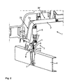
- FIG. 2 shows the bolted to a frame rail by means of a bearing block 7 bearing assembly 3, which establishes a connection between the cross-beam 2 and the frame rail 4.
- the bearing assembly here, as already described above, in addition to the bearing block 7 via a spring-damper unit 5 and a unit for side guide 6.
- the spring damper unit 5 allows vertical movement of the cab up to a predetermined maximum vertical movement.
- the guide element with its backdrop-like leadership has different running games and sometimes a delay, it can come with vertical movements with the known guide rollers to a noise.
- squeaking sounds may occur because such rolls tend to become stuck.
- hard rollers such as the well-known polyamide guide rollers, it can, in contrast, come about as when stopping the engine to rattling noises.
- the inventively designed guide roller 12 of the side guide 6 therefore has a storable inner part, or inner sleeve, and a soft, relatively wear-free outer part.
- Both inner and outer part are designed as a hollow cylinder, wherein the outer diameter of the inner part substantially, in particular without consideration of the specially contoured contact areas, corresponds to the inner diameter of the outer part.
- a suitable guide roller 12 of the side guide 6 is therefore designed as a hybrid role with an inner part having polyoxymethylene (POM), and an outer part, which has a thermoplastic polyolefin, in particular Thermopren ® or Neoprene ® , has.
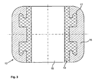
- FIG. 3 shows a longitudinal sectional view of an inventively designed guide roller 12.
- the guide roller 12 via a cylindrical, arranged symmetrically about the longitudinal center axis recess 16, in which a right and a left bearing bush and a screw 13 are inserted during assembly.
- the guide roller 12 has an inner 14 and an outer part 15, which form a contact surface in the region of their outer and inner circumferential surfaces with each other.
- the inner part 14 has according to the invention over a polyoxymethylene (POM), while the outer member 15 is made of a polyolefin elastomer, which is for example available under the trade designation thermoprene ®.
- the interior 14 and the outer part 15 via a suitable contour 17, which allows an at least partially positive connection of the two parts.
- the contour 17 is characterized by an undercut, which is provided on the back mushroom-like elevations of the lateral surface of the inner part 14.
- the contour 17 ensures that the inner 14 and outer part 15 of the guide roller 12 remain permanently connected and are not separated by flexing, impact forces, high-pressure cleaning, UV rays and the like from each other.
- Essential for the geometry of the inner 14 and the outer part 15 in addition to the special contour 17 is that the largest wall thickness of the outer part 15 is present in the central region, where the introduction of force into the roller 12 is predominantly.
- guide roller 12 thus ensures that rear cab bearings that are supported together on a fixed to the chassis frame crossmember 2, can be realized, which are particularly resistant to wear and are reliably prevented by the formation of disturbing squeaking and / or rattling noises in the storage area can.
Landscapes
- Engineering & Computer Science (AREA)
- Chemical & Material Sciences (AREA)
- Combustion & Propulsion (AREA)
- Transportation (AREA)
- Mechanical Engineering (AREA)
- Body Structure For Vehicles (AREA)
- Laminated Bodies (AREA)
- Vibration Prevention Devices (AREA)
- Support Of The Bearing (AREA)
Applications Claiming Priority (1)
| Application Number | Priority Date | Filing Date | Title |
|---|---|---|---|
| ATA442/2012A AT512664B1 (de) | 2012-04-12 | 2012-04-12 | Hintere Lagerung eines Nutzfahrzeugfahrerhauses |
Publications (3)
| Publication Number | Publication Date |
|---|---|
| EP2650195A2 true EP2650195A2 (fr) | 2013-10-16 |
| EP2650195A3 EP2650195A3 (fr) | 2013-11-20 |
| EP2650195B1 EP2650195B1 (fr) | 2015-01-07 |
Family
ID=47227414
Family Applications (1)
| Application Number | Title | Priority Date | Filing Date |
|---|---|---|---|
| EP12007728.4A Active EP2650195B1 (fr) | 2012-04-12 | 2012-11-15 | Articulation postérieure pour cabine de véhicule utilitaire |
Country Status (5)
| Country | Link |
|---|---|
| EP (1) | EP2650195B1 (fr) |
| CN (1) | CN103373399B (fr) |
| AT (1) | AT512664B1 (fr) |
| BR (1) | BR102013008753B1 (fr) |
| RU (1) | RU2615235C2 (fr) |
Cited By (5)
| Publication number | Priority date | Publication date | Assignee | Title |
|---|---|---|---|---|
| CN106828620A (zh) * | 2017-01-25 | 2017-06-13 | 安徽江淮汽车集团股份有限公司 | 驾驶室翻转扭力调节机构 |
| EP4219275A1 (fr) * | 2022-01-31 | 2023-08-02 | Deere & Company | Système de montage de cabine et montage de cabine |
| EP4219276A1 (fr) * | 2022-01-31 | 2023-08-02 | Deere & Company | Système de montage de cabine et montage de cabine |
| EP4219277A1 (fr) * | 2022-01-31 | 2023-08-02 | Deere & Company | Système de montage de cabine et montage de cabine |
| US12286162B2 (en) | 2022-01-31 | 2025-04-29 | Deere & Company | Cab mounting system and cab mounting |
Families Citing this family (3)
| Publication number | Priority date | Publication date | Assignee | Title |
|---|---|---|---|---|
| DE102015214456A1 (de) * | 2015-07-30 | 2017-02-02 | Deere & Company | Kabinenlagerungsanordnung für ein Nutzfahrzeug |
| CN114701576B (zh) * | 2022-04-02 | 2023-10-27 | 中国重汽集团济南动力有限公司 | 一种驾驶室后悬空气弹簧减振装置 |
| CN116923572A (zh) * | 2023-07-03 | 2023-10-24 | 一汽解放汽车有限公司 | 车辆驾驶室的悬置支架和车辆 |
Family Cites Families (10)
| Publication number | Priority date | Publication date | Assignee | Title |
|---|---|---|---|---|
| AT366330B (de) * | 1980-05-14 | 1982-04-13 | Steyr Daimler Puch Ag | Lagerung eines insbesondere kippbaren fahrerhauses eines lastkraftwagens |
| AT403364B (de) * | 1996-02-27 | 1998-01-26 | Steyr Nutzfahrzeuge | Lastkraftwagen mit nach vorne kippbarem fahrerhaus |
| AT407034B (de) * | 1999-02-11 | 2000-11-27 | Steyr Nutzfahrzeuge | Hintere lagerung des kippbaren fahrerhauses eines frontlenker-lastkraftwagens |
| AT410928B (de) * | 2002-02-11 | 2003-08-25 | Man Steyr Ag | Hintere lagerung des kippbaren fahrerhauses eines frontlenker-lastkraftwagen |
| US20040012247A1 (en) * | 2002-07-16 | 2004-01-22 | Shih-Yuan Lin | Wheel assembly for child bicycles |
| US7090306B1 (en) * | 2003-06-12 | 2006-08-15 | Piper Neal W | Inline wheel with softer tire and internal support structure |
| JP5148266B2 (ja) * | 2005-01-31 | 2013-02-20 | 株式会社小松製作所 | チルトフロアを備えた作業車両 |
| DE102007013241A1 (de) * | 2007-03-15 | 2008-09-18 | Carl Freudenberg Kg | Fahrzeug |
| KR20100059564A (ko) * | 2008-11-26 | 2010-06-04 | 현대자동차주식회사 | 차량의 캡 서스펜션 |
| CN201427611Y (zh) * | 2009-06-25 | 2010-03-24 | 陕西汽车集团有限责任公司 | 改进的汽车驾驶室翻转轴承 |
-
2012
- 2012-04-12 AT ATA442/2012A patent/AT512664B1/de active
- 2012-11-15 EP EP12007728.4A patent/EP2650195B1/fr active Active
-
2013
- 2013-03-25 RU RU2013113282A patent/RU2615235C2/ru active
- 2013-04-10 BR BR102013008753-0A patent/BR102013008753B1/pt active IP Right Grant
- 2013-04-12 CN CN201310125962.5A patent/CN103373399B/zh active Active
Cited By (7)
| Publication number | Priority date | Publication date | Assignee | Title |
|---|---|---|---|---|
| CN106828620A (zh) * | 2017-01-25 | 2017-06-13 | 安徽江淮汽车集团股份有限公司 | 驾驶室翻转扭力调节机构 |
| EP4219275A1 (fr) * | 2022-01-31 | 2023-08-02 | Deere & Company | Système de montage de cabine et montage de cabine |
| EP4219276A1 (fr) * | 2022-01-31 | 2023-08-02 | Deere & Company | Système de montage de cabine et montage de cabine |
| EP4219277A1 (fr) * | 2022-01-31 | 2023-08-02 | Deere & Company | Système de montage de cabine et montage de cabine |
| US12286162B2 (en) | 2022-01-31 | 2025-04-29 | Deere & Company | Cab mounting system and cab mounting |
| US12286161B2 (en) | 2022-01-31 | 2025-04-29 | Deere & Company | Cab mounting system and cab mounting |
| US12391317B2 (en) | 2022-01-31 | 2025-08-19 | Deere & Company | Cab mounting system and cab mounting |
Also Published As
| Publication number | Publication date |
|---|---|
| BR102013008753B1 (pt) | 2021-11-30 |
| AT512664B1 (de) | 2013-10-15 |
| EP2650195A3 (fr) | 2013-11-20 |
| RU2013113282A (ru) | 2014-09-27 |
| RU2615235C2 (ru) | 2017-04-04 |
| AT512664A4 (de) | 2013-10-15 |
| BR102013008753A2 (pt) | 2015-06-23 |
| CN103373399B (zh) | 2016-12-28 |
| EP2650195B1 (fr) | 2015-01-07 |
| CN103373399A (zh) | 2013-10-30 |
Similar Documents
| Publication | Publication Date | Title |
|---|---|---|
| EP2650195B1 (fr) | Articulation postérieure pour cabine de véhicule utilitaire | |
| DE102006058604B4 (de) | Crashbox | |
| DE2726676A1 (de) | Federelement, insbesondere zur elastischen lagerung von antriebs- oder sonstigen aggregaten in kraftfahrzeugen | |
| DE102011106285B4 (de) | Beschlagsystem für einen Fahrzeugsitz und Fahrzeugsitz | |
| EP2248688B1 (fr) | Dispositif de remorquage | |
| DE19839519A1 (de) | Fahrgastzelle | |
| DE2825460A1 (de) | Energieabsorber, insbesondere fuer motorfahrzeuge | |
| DE10036553B4 (de) | Vorrichtung zum Verankern eines Sitzes an einem Fahrzeugboden | |
| DE102011118150A1 (de) | Lagerung eines Funktionselements in einem Schienenpaar innerhalb eines Fahrgastraums eines Kraftfahrzeugs | |
| EP3860868A2 (fr) | Attelage de remorque | |
| DE19811917A1 (de) | Kupplungsmechanismus für eine Zahnstange und deren Antriebsritzel | |
| DE20205029U1 (de) | Armlehne mit beweglicher Armauflage, insbesondere für Fahrzeuge | |
| EP2409627A2 (fr) | Aspirateur au sol doté d'un boîtier mobile sur rouleaux | |
| DE102009032919B4 (de) | Federungsanordnung mit einer Blattfeder aus einem Faserverbundwerkstoff | |
| DE102012017319B4 (de) | Befestigungsanordnung zwischen einem Radiallager und einem Stützarm | |
| DE10052829B4 (de) | Vorrichtung zur Arretierung eines beweglichen Körpers, insbesondere in einem Kfz und Armlehne | |
| DE69505601T2 (de) | Perfektionierter Energiedämpfer für Kraftfahrzeug | |
| EP3665022A1 (fr) | Unité de découplage et stabilisateur antiroulis doté d'une telle unité de découplage | |
| WO2021073686A1 (fr) | Palier à rouleaux incliné pour dispositif de palier serré d'arbre de direction de colonne de direction, et dispositif de palier pour arbre de direction de colonne de direction | |
| DE19913777C1 (de) | Gelenklager, insbesondere zur Lagerung von Achslenkern in Kraftfahrzeugen | |
| DE102018125810A1 (de) | Fahrgestell, Federungssystem und Anhänger | |
| DE102013005543A1 (de) | Achsführungslager zur Ankopplung einer Hinterachse an einen Fahrzeugaufbau eines Kraftfahrzeugs | |
| DE19918923C1 (de) | Beschlag für einen Fahrzeugsitz | |
| DE19706609C5 (de) | Vorrichtung zur Befestigung des Lenkrads in einem Kraftfahrzeug | |
| DE102017218795B4 (de) | Achsaufhängung |
Legal Events
| Date | Code | Title | Description |
|---|---|---|---|
| PUAI | Public reference made under article 153(3) epc to a published international application that has entered the european phase |
Free format text: ORIGINAL CODE: 0009012 |
|
| AK | Designated contracting states |
Kind code of ref document: A2 Designated state(s): AL AT BE BG CH CY CZ DE DK EE ES FI FR GB GR HR HU IE IS IT LI LT LU LV MC MK MT NL NO PL PT RO RS SE SI SK SM TR |
|
| AX | Request for extension of the european patent |
Extension state: BA ME |
|
| PUAL | Search report despatched |
Free format text: ORIGINAL CODE: 0009013 |
|
| AK | Designated contracting states |
Kind code of ref document: A3 Designated state(s): AL AT BE BG CH CY CZ DE DK EE ES FI FR GB GR HR HU IE IS IT LI LT LU LV MC MK MT NL NO PL PT RO RS SE SI SK SM TR |
|
| AX | Request for extension of the european patent |
Extension state: BA ME |
|
| RIC1 | Information provided on ipc code assigned before grant |
Ipc: B62D 33/06 20060101AFI20131015BHEP Ipc: B62D 33/067 20060101ALI20131015BHEP Ipc: B62D 33/07 20060101ALI20131015BHEP |
|
| 17P | Request for examination filed |
Effective date: 20131106 |
|
| GRAP | Despatch of communication of intention to grant a patent |
Free format text: ORIGINAL CODE: EPIDOSNIGR1 |
|
| RIC1 | Information provided on ipc code assigned before grant |
Ipc: B62D 33/07 20060101ALI20140704BHEP Ipc: B62D 33/067 20060101ALI20140704BHEP Ipc: B62D 33/06 20060101AFI20140704BHEP |
|
| INTG | Intention to grant announced |
Effective date: 20140730 |
|
| GRAS | Grant fee paid |
Free format text: ORIGINAL CODE: EPIDOSNIGR3 |
|
| GRAA | (expected) grant |
Free format text: ORIGINAL CODE: 0009210 |
|
| AK | Designated contracting states |
Kind code of ref document: B1 Designated state(s): AL AT BE BG CH CY CZ DE DK EE ES FI FR GB GR HR HU IE IS IT LI LT LU LV MC MK MT NL NO PL PT RO RS SE SI SK SM TR |
|
| REG | Reference to a national code |
Ref country code: GB Ref legal event code: FG4D Free format text: NOT ENGLISH |
|
| REG | Reference to a national code |
Ref country code: CH Ref legal event code: EP |
|
| REG | Reference to a national code |
Ref country code: IE Ref legal event code: FG4D Free format text: LANGUAGE OF EP DOCUMENT: GERMAN |
|
| REG | Reference to a national code |
Ref country code: AT Ref legal event code: REF Ref document number: 705475 Country of ref document: AT Kind code of ref document: T Effective date: 20150215 |
|
| REG | Reference to a national code |
Ref country code: DE Ref legal event code: R096 Ref document number: 502012002003 Country of ref document: DE Effective date: 20150219 |
|
| REG | Reference to a national code |
Ref country code: NL Ref legal event code: T3 |
|
| REG | Reference to a national code |
Ref country code: SE Ref legal event code: TRGR |
|
| REG | Reference to a national code |
Ref country code: LT Ref legal event code: MG4D |
|
| PG25 | Lapsed in a contracting state [announced via postgrant information from national office to epo] |
Ref country code: HR Free format text: LAPSE BECAUSE OF FAILURE TO SUBMIT A TRANSLATION OF THE DESCRIPTION OR TO PAY THE FEE WITHIN THE PRESCRIBED TIME-LIMIT Effective date: 20150107 Ref country code: NO Free format text: LAPSE BECAUSE OF FAILURE TO SUBMIT A TRANSLATION OF THE DESCRIPTION OR TO PAY THE FEE WITHIN THE PRESCRIBED TIME-LIMIT Effective date: 20150407 Ref country code: FI Free format text: LAPSE BECAUSE OF FAILURE TO SUBMIT A TRANSLATION OF THE DESCRIPTION OR TO PAY THE FEE WITHIN THE PRESCRIBED TIME-LIMIT Effective date: 20150107 Ref country code: ES Free format text: LAPSE BECAUSE OF FAILURE TO SUBMIT A TRANSLATION OF THE DESCRIPTION OR TO PAY THE FEE WITHIN THE PRESCRIBED TIME-LIMIT Effective date: 20150107 Ref country code: BG Free format text: LAPSE BECAUSE OF FAILURE TO SUBMIT A TRANSLATION OF THE DESCRIPTION OR TO PAY THE FEE WITHIN THE PRESCRIBED TIME-LIMIT Effective date: 20150407 Ref country code: LT Free format text: LAPSE BECAUSE OF FAILURE TO SUBMIT A TRANSLATION OF THE DESCRIPTION OR TO PAY THE FEE WITHIN THE PRESCRIBED TIME-LIMIT Effective date: 20150107 |
|
| PG25 | Lapsed in a contracting state [announced via postgrant information from national office to epo] |
Ref country code: IS Free format text: LAPSE BECAUSE OF FAILURE TO SUBMIT A TRANSLATION OF THE DESCRIPTION OR TO PAY THE FEE WITHIN THE PRESCRIBED TIME-LIMIT Effective date: 20150507 Ref country code: GR Free format text: LAPSE BECAUSE OF FAILURE TO SUBMIT A TRANSLATION OF THE DESCRIPTION OR TO PAY THE FEE WITHIN THE PRESCRIBED TIME-LIMIT Effective date: 20150408 Ref country code: PL Free format text: LAPSE BECAUSE OF FAILURE TO SUBMIT A TRANSLATION OF THE DESCRIPTION OR TO PAY THE FEE WITHIN THE PRESCRIBED TIME-LIMIT Effective date: 20150107 Ref country code: LV Free format text: LAPSE BECAUSE OF FAILURE TO SUBMIT A TRANSLATION OF THE DESCRIPTION OR TO PAY THE FEE WITHIN THE PRESCRIBED TIME-LIMIT Effective date: 20150107 Ref country code: RS Free format text: LAPSE BECAUSE OF FAILURE TO SUBMIT A TRANSLATION OF THE DESCRIPTION OR TO PAY THE FEE WITHIN THE PRESCRIBED TIME-LIMIT Effective date: 20150107 |
|
| REG | Reference to a national code |
Ref country code: DE Ref legal event code: R097 Ref document number: 502012002003 Country of ref document: DE |
|
| PG25 | Lapsed in a contracting state [announced via postgrant information from national office to epo] |
Ref country code: CZ Free format text: LAPSE BECAUSE OF FAILURE TO SUBMIT A TRANSLATION OF THE DESCRIPTION OR TO PAY THE FEE WITHIN THE PRESCRIBED TIME-LIMIT Effective date: 20150107 Ref country code: RO Free format text: LAPSE BECAUSE OF FAILURE TO SUBMIT A TRANSLATION OF THE DESCRIPTION OR TO PAY THE FEE WITHIN THE PRESCRIBED TIME-LIMIT Effective date: 20150107 Ref country code: EE Free format text: LAPSE BECAUSE OF FAILURE TO SUBMIT A TRANSLATION OF THE DESCRIPTION OR TO PAY THE FEE WITHIN THE PRESCRIBED TIME-LIMIT Effective date: 20150107 Ref country code: DK Free format text: LAPSE BECAUSE OF FAILURE TO SUBMIT A TRANSLATION OF THE DESCRIPTION OR TO PAY THE FEE WITHIN THE PRESCRIBED TIME-LIMIT Effective date: 20150107 Ref country code: SK Free format text: LAPSE BECAUSE OF FAILURE TO SUBMIT A TRANSLATION OF THE DESCRIPTION OR TO PAY THE FEE WITHIN THE PRESCRIBED TIME-LIMIT Effective date: 20150107 |
|
| PLBE | No opposition filed within time limit |
Free format text: ORIGINAL CODE: 0009261 |
|
| STAA | Information on the status of an ep patent application or granted ep patent |
Free format text: STATUS: NO OPPOSITION FILED WITHIN TIME LIMIT |
|
| REG | Reference to a national code |
Ref country code: FR Ref legal event code: PLFP Year of fee payment: 4 |
|
| 26N | No opposition filed |
Effective date: 20151008 |
|
| PG25 | Lapsed in a contracting state [announced via postgrant information from national office to epo] |
Ref country code: SI Free format text: LAPSE BECAUSE OF FAILURE TO SUBMIT A TRANSLATION OF THE DESCRIPTION OR TO PAY THE FEE WITHIN THE PRESCRIBED TIME-LIMIT Effective date: 20150107 |
|
| PG25 | Lapsed in a contracting state [announced via postgrant information from national office to epo] |
Ref country code: MC Free format text: LAPSE BECAUSE OF FAILURE TO SUBMIT A TRANSLATION OF THE DESCRIPTION OR TO PAY THE FEE WITHIN THE PRESCRIBED TIME-LIMIT Effective date: 20150107 Ref country code: LU Free format text: LAPSE BECAUSE OF FAILURE TO SUBMIT A TRANSLATION OF THE DESCRIPTION OR TO PAY THE FEE WITHIN THE PRESCRIBED TIME-LIMIT Effective date: 20151115 |
|
| REG | Reference to a national code |
Ref country code: CH Ref legal event code: PL |
|
| PG25 | Lapsed in a contracting state [announced via postgrant information from national office to epo] |
Ref country code: CH Free format text: LAPSE BECAUSE OF NON-PAYMENT OF DUE FEES Effective date: 20151130 Ref country code: LI Free format text: LAPSE BECAUSE OF NON-PAYMENT OF DUE FEES Effective date: 20151130 |
|
| REG | Reference to a national code |
Ref country code: IE Ref legal event code: MM4A |
|
| PG25 | Lapsed in a contracting state [announced via postgrant information from national office to epo] |
Ref country code: IE Free format text: LAPSE BECAUSE OF NON-PAYMENT OF DUE FEES Effective date: 20151115 |
|
| REG | Reference to a national code |
Ref country code: FR Ref legal event code: PLFP Year of fee payment: 5 |
|
| PG25 | Lapsed in a contracting state [announced via postgrant information from national office to epo] |
Ref country code: HU Free format text: LAPSE BECAUSE OF FAILURE TO SUBMIT A TRANSLATION OF THE DESCRIPTION OR TO PAY THE FEE WITHIN THE PRESCRIBED TIME-LIMIT; INVALID AB INITIO Effective date: 20121115 Ref country code: SM Free format text: LAPSE BECAUSE OF FAILURE TO SUBMIT A TRANSLATION OF THE DESCRIPTION OR TO PAY THE FEE WITHIN THE PRESCRIBED TIME-LIMIT Effective date: 20150107 |
|
| PG25 | Lapsed in a contracting state [announced via postgrant information from national office to epo] |
Ref country code: CY Free format text: LAPSE BECAUSE OF FAILURE TO SUBMIT A TRANSLATION OF THE DESCRIPTION OR TO PAY THE FEE WITHIN THE PRESCRIBED TIME-LIMIT Effective date: 20150107 |
|
| GBPC | Gb: european patent ceased through non-payment of renewal fee |
Effective date: 20161115 |
|
| PG25 | Lapsed in a contracting state [announced via postgrant information from national office to epo] |
Ref country code: BE Free format text: LAPSE BECAUSE OF NON-PAYMENT OF DUE FEES Effective date: 20151130 |
|
| PG25 | Lapsed in a contracting state [announced via postgrant information from national office to epo] |
Ref country code: MT Free format text: LAPSE BECAUSE OF FAILURE TO SUBMIT A TRANSLATION OF THE DESCRIPTION OR TO PAY THE FEE WITHIN THE PRESCRIBED TIME-LIMIT Effective date: 20150107 |
|
| REG | Reference to a national code |
Ref country code: FR Ref legal event code: PLFP Year of fee payment: 6 |
|
| PG25 | Lapsed in a contracting state [announced via postgrant information from national office to epo] |
Ref country code: GB Free format text: LAPSE BECAUSE OF NON-PAYMENT OF DUE FEES Effective date: 20161115 |
|
| PG25 | Lapsed in a contracting state [announced via postgrant information from national office to epo] |
Ref country code: TR Free format text: LAPSE BECAUSE OF FAILURE TO SUBMIT A TRANSLATION OF THE DESCRIPTION OR TO PAY THE FEE WITHIN THE PRESCRIBED TIME-LIMIT Effective date: 20150107 Ref country code: MK Free format text: LAPSE BECAUSE OF FAILURE TO SUBMIT A TRANSLATION OF THE DESCRIPTION OR TO PAY THE FEE WITHIN THE PRESCRIBED TIME-LIMIT Effective date: 20150107 Ref country code: PT Free format text: LAPSE BECAUSE OF FAILURE TO SUBMIT A TRANSLATION OF THE DESCRIPTION OR TO PAY THE FEE WITHIN THE PRESCRIBED TIME-LIMIT Effective date: 20150107 |
|
| PG25 | Lapsed in a contracting state [announced via postgrant information from national office to epo] |
Ref country code: AL Free format text: LAPSE BECAUSE OF FAILURE TO SUBMIT A TRANSLATION OF THE DESCRIPTION OR TO PAY THE FEE WITHIN THE PRESCRIBED TIME-LIMIT Effective date: 20150107 |
|
| REG | Reference to a national code |
Ref country code: AT Ref legal event code: MM01 Ref document number: 705475 Country of ref document: AT Kind code of ref document: T Effective date: 20171115 |
|
| PG25 | Lapsed in a contracting state [announced via postgrant information from national office to epo] |
Ref country code: AT Free format text: LAPSE BECAUSE OF NON-PAYMENT OF DUE FEES Effective date: 20171115 |
|
| REG | Reference to a national code |
Ref country code: DE Ref legal event code: R081 Ref document number: 502012002003 Country of ref document: DE Owner name: MAN TRUCK & BUS SE, DE Free format text: FORMER OWNER: MAN TRUCK & BUS OESTERREICH AG, STEYR, AT |
|
| REG | Reference to a national code |
Ref country code: NL Ref legal event code: PD Owner name: MAN TRUCK & BUS OESTERREICH GESMBH; AT Free format text: DETAILS ASSIGNMENT: CHANGE OF OWNER(S), ASSIGNMENT; FORMER OWNER NAME: MAN TRUCK & BUS OESTERREICH GESMBH Effective date: 20231031 |
|
| PGFP | Annual fee paid to national office [announced via postgrant information from national office to epo] |
Ref country code: NL Payment date: 20251124 Year of fee payment: 14 |
|
| PGFP | Annual fee paid to national office [announced via postgrant information from national office to epo] |
Ref country code: DE Payment date: 20251126 Year of fee payment: 14 |
|
| PGFP | Annual fee paid to national office [announced via postgrant information from national office to epo] |
Ref country code: IT Payment date: 20251121 Year of fee payment: 14 |
|
| PGFP | Annual fee paid to national office [announced via postgrant information from national office to epo] |
Ref country code: FR Payment date: 20251124 Year of fee payment: 14 |
|
| PGFP | Annual fee paid to national office [announced via postgrant information from national office to epo] |
Ref country code: SE Payment date: 20251124 Year of fee payment: 14 |