EP2650445A2 - Elément de base pouvant être abaissé au niveau de la mer pour des dispositifs fixes - Google Patents
Elément de base pouvant être abaissé au niveau de la mer pour des dispositifs fixes Download PDFInfo
- Publication number
- EP2650445A2 EP2650445A2 EP13401035.4A EP13401035A EP2650445A2 EP 2650445 A2 EP2650445 A2 EP 2650445A2 EP 13401035 A EP13401035 A EP 13401035A EP 2650445 A2 EP2650445 A2 EP 2650445A2
- Authority
- EP
- European Patent Office
- Prior art keywords
- base element
- base
- supports
- buoyancy
- frame
- Prior art date
- Legal status (The legal status is an assumption and is not a legal conclusion. Google has not performed a legal analysis and makes no representation as to the accuracy of the status listed.)
- Withdrawn
Links
- 238000009434 installation Methods 0.000 title claims description 11
- 239000000463 material Substances 0.000 claims abstract description 43
- 239000004576 sand Substances 0.000 claims description 14
- 239000013049 sediment Substances 0.000 claims description 11
- 239000004753 textile Substances 0.000 claims description 5
- XLYOFNOQVPJJNP-UHFFFAOYSA-N water Substances O XLYOFNOQVPJJNP-UHFFFAOYSA-N 0.000 description 16
- 238000000034 method Methods 0.000 description 7
- 238000010276 construction Methods 0.000 description 6
- 239000004746 geotextile Substances 0.000 description 5
- 239000007787 solid Substances 0.000 description 5
- 229910000831 Steel Inorganic materials 0.000 description 4
- 238000004873 anchoring Methods 0.000 description 4
- 239000010959 steel Substances 0.000 description 4
- 241000196324 Embryophyta Species 0.000 description 3
- 239000004744 fabric Substances 0.000 description 3
- 239000002689 soil Substances 0.000 description 3
- 230000006978 adaptation Effects 0.000 description 2
- 230000007613 environmental effect Effects 0.000 description 2
- 238000011900 installation process Methods 0.000 description 2
- 238000002360 preparation method Methods 0.000 description 2
- 230000000717 retained effect Effects 0.000 description 2
- 241000251468 Actinopterygii Species 0.000 description 1
- 241000283153 Cetacea Species 0.000 description 1
- 241000237536 Mytilus edulis Species 0.000 description 1
- 241000237502 Ostreidae Species 0.000 description 1
- 241000209504 Poaceae Species 0.000 description 1
- 239000000853 adhesive Substances 0.000 description 1
- 230000001070 adhesive effect Effects 0.000 description 1
- QVGXLLKOCUKJST-UHFFFAOYSA-N atomic oxygen Chemical compound [O] QVGXLLKOCUKJST-UHFFFAOYSA-N 0.000 description 1
- 150000001875 compounds Chemical class 0.000 description 1
- 238000007796 conventional method Methods 0.000 description 1
- 238000012937 correction Methods 0.000 description 1
- 238000005260 corrosion Methods 0.000 description 1
- 230000007797 corrosion Effects 0.000 description 1
- 230000001419 dependent effect Effects 0.000 description 1
- 238000013461 design Methods 0.000 description 1
- 238000006073 displacement reaction Methods 0.000 description 1
- 238000005553 drilling Methods 0.000 description 1
- 230000000694 effects Effects 0.000 description 1
- 239000007789 gas Substances 0.000 description 1
- 230000005484 gravity Effects 0.000 description 1
- 239000011440 grout Substances 0.000 description 1
- 238000011835 investigation Methods 0.000 description 1
- 230000007774 longterm Effects 0.000 description 1
- 239000000203 mixture Substances 0.000 description 1
- 238000012986 modification Methods 0.000 description 1
- 230000004048 modification Effects 0.000 description 1
- 230000005404 monopole Effects 0.000 description 1
- 235000020638 mussel Nutrition 0.000 description 1
- 239000001301 oxygen Substances 0.000 description 1
- 229910052760 oxygen Inorganic materials 0.000 description 1
- 235000020636 oyster Nutrition 0.000 description 1
- 230000000149 penetrating effect Effects 0.000 description 1
- 230000035515 penetration Effects 0.000 description 1
- 239000011148 porous material Substances 0.000 description 1
- 230000002787 reinforcement Effects 0.000 description 1
- 230000000284 resting effect Effects 0.000 description 1
- 239000013535 sea water Substances 0.000 description 1
- 238000000926 separation method Methods 0.000 description 1
- 239000010802 sludge Substances 0.000 description 1
- 239000008234 soft water Substances 0.000 description 1
- 238000007711 solidification Methods 0.000 description 1
- 230000008023 solidification Effects 0.000 description 1
- 241000894007 species Species 0.000 description 1
- 230000006641 stabilisation Effects 0.000 description 1
- 238000011105 stabilization Methods 0.000 description 1
- 230000003068 static effect Effects 0.000 description 1
- 239000003643 water by type Substances 0.000 description 1
Images




Classifications
-
- E—FIXED CONSTRUCTIONS
- E02—HYDRAULIC ENGINEERING; FOUNDATIONS; SOIL SHIFTING
- E02D—FOUNDATIONS; EXCAVATIONS; EMBANKMENTS; UNDERGROUND OR UNDERWATER STRUCTURES
- E02D27/00—Foundations as substructures
- E02D27/32—Foundations for special purposes
- E02D27/52—Submerged foundations, i.e. submerged in open water
-
- Y—GENERAL TAGGING OF NEW TECHNOLOGICAL DEVELOPMENTS; GENERAL TAGGING OF CROSS-SECTIONAL TECHNOLOGIES SPANNING OVER SEVERAL SECTIONS OF THE IPC; TECHNICAL SUBJECTS COVERED BY FORMER USPC CROSS-REFERENCE ART COLLECTIONS [XRACs] AND DIGESTS
- Y02—TECHNOLOGIES OR APPLICATIONS FOR MITIGATION OR ADAPTATION AGAINST CLIMATE CHANGE
- Y02B—CLIMATE CHANGE MITIGATION TECHNOLOGIES RELATED TO BUILDINGS, e.g. HOUSING, HOUSE APPLIANCES OR RELATED END-USER APPLICATIONS
- Y02B10/00—Integration of renewable energy sources in buildings
- Y02B10/30—Wind power
Definitions
- the invention relates to a base element which can be lowered to a bottom, in particular seabed, for stationary installations, in particular wind energy installations, structures or navigational signs, with a bottom surface which can be lowered to the ground and with a base for receiving the device.
- the most economical method for introducing the pipe into the ground is the piling method.
- the rinsing process is also known.
- the drilling process continues to be used, in which the monopile is optionally cemented with a concrete-like mass (grout) into the borehole depending on the soil condition.
- tripods and so-called jackets, four-legged or multi-legged platforms, mostly designed as truss structures, are included as a basic element to the well-known foundation options for wind turbines.
- the anchoring can be done both by its own weight as well as anchored in the ground piles. Due to the significantly higher steel consumption and the large number of anchoring points on the ocean floor, which are associated with considerable effort, these foundations are far less economical than the monopile. Furthermore, the spatial extent below the water surface represents an increased risk for ship collisions.
- floating platform shells have also been used, commonly known as MOAB (Mobile Offshore Application Barge) for example in the EP 2 204 497 A1 have been described.
- MOAB Mobile Offshore Application Barge
- parts of the arrangement can be lifted substantially out of the water and lowered to the seabed only at the installation site.
- the platform shell is generally in such an intermediate position between the described first and second positions that it floats in the waterline. Due to the additionally required mechanics such solutions are complex and prone to errors.
- the invention is therefore an object of the invention to provide a primitive which has a relatively low weight and is easy to transport.
- an optimized floor support should be created.
- a basic element which is provided with at least one floor support which can be placed on the ground, which has a flexible surface material which can be placed on the base and which is arranged on a plurality of holding points arranged on the circumference of the surface material and spanning the surface material, in particular formed by a frame is, wherein the sheet material is movable, for example, at its breakpoints from a rest position to a working position.
- the invention is based on the consideration that the preferably textile, water-permeable surface material deposited on the ground and can be weighted with the available solids in the environment, such as sand and sediment.
- the surface material for solids from a certain grain size is impermeable.
- sediment deposits on the surface material, which further improves anchoring on the ground.
- Correspondingly shaped pockets can serve as a receptacle for solid components and can be filled in a simple manner, for example during assembly with sand.
- the present invention is based on the idea of a flexible adaptation to the ground in connection with a large bearing surface, through which anchoring in the ground is achieved.
- the supports can be provided with corresponding breakpoints, if they are, for example, similar to a screen pivotally relative to each other, so as to one
- the surface material could be stretched similar to a screen by moving struts and brought into the desired defined position.
- the base element has a number of frames which can be moved, in particular from a rest position into a working position, that is to say into a horizontal or with respect to this only slightly inclined plane.
- the supports can bring independently of the réellespannenden sheet material in a working position and settle on the ground, while the surface-increasing and the desired load-ensuring bottom surface is realized by a pivoting movement in the predetermined working position.
- the position of the base element can be achieved comparatively easily before the surface material is subjected to ballast and thus the position is finally determined.
- the supports are connected by a plurality of struts to a foundation ring on which at least one frame is arranged radially inwardly or outwardly hinged.
- the flexible sheet material can be variably adapted to different holding points on the supports or the frame.
- the basic element is not limited to a certain number of supports or struts, but it has already proven to be advantageous if at least three mutually inclined supports are provided, which form a grid structure and include a particular matching angle to a bottom surface.
- the supports or the struts are connected, for example, by a foundation ring on the circumference or in a central area, in particular in a star shape. Furthermore, adjacent supports may be connected at their respective end portion by the foundation ring or by a traction means so as to be able to absorb the forces occurring and at the same time not substantially increase the weight.
- the supports are adjustably connected to the base in each case by means of a joint.
- a smooth alignment of the base can be achieved, especially in a horizontal plane.
- the supports are designed to be adjustable in length and even then allow the desired orientation of the base plane when the base is inclined or arched.
- At least one support for aligning the base in a predetermined, in particular horizontal plane in the direction of its main extension has an adjustable length.
- the shape of the floor surface follows the local conditions and the expected load on the basic element.
- the bottom surface has a polygonal shape and is preferably symmetrical, depending on the expected external forces also asymmetrically positioned with respect to a central axis between the supports.
- the sheet material may also have a different nature in different areas, so as to protect, for example, particularly stressed areas by reinforcements. It proves to be particularly practical if the sheet material consists of several segments that can be used as needed in the frame or arranged to be interchangeable.
- the stability of the base element can also be significantly increased in a simple manner by the floor surface being fixable on the base at least in sections by means of at least one ground anchor, in particular with a penetration tip.
- the basic element is fixed by means of the ground anchors before the unfolding of the sheet material frame, so that an undesirable displacement is reliably avoided.
- the base element from a transport position in which at least individual supports are arranged substantially adjacent to each other, is movable into a use position, in which the supports are pivoted in a spread position.
- the transport volume can be minimized.
- the base element from the transport position in the use position by the action of a lifting force, in particular a buoyancy force is movable, so that the base element aligns almost automatically under the action of the buoyancy force in the predetermined position of use.
- the base element may have a buoyancy element, in particular detachably connected to the base element, with adjustable buoyancy force in order to be able to set the desired orientation of the base element, for example by supplying air to the buoyancy element.
- the buoyancy element can be equipped with a flexible and / or elastic, with a gas, in particular compressed air acted upon buoyancy body or with a hollow body with adjustable volume.
- the buoyancy element may have a plurality of buoyancy elements which can be acted upon independently with an adjustable buoyancy force, arranged in the direction of the longitudinal extension between the base surface and the base.
- the maximum adjustable buoyancy force of the buoyancy element may exceed the dead weight of the base element, so as to obtain a buoyancy of the base element.
- the base element can be towed, for example, up to the predetermined setting position and lowered there.
- the base element can be brought into a substantially vertically floating and / or lowered orientation by changing the buoyancy force of one or more buoyancy elements, starting from a substantially horizontally floating orientation.
- the minimum adjustable buoyancy force is equal to or slightly greater than the weight of the buoyancy element.
- the base element can be acted upon with an additional weight, which is preferably supported on the base, so as to increase the stability of the base member, if necessary.
- the base element according to the invention requires much less effort due to the ground support made of the flexible sheet material.
- the main advantages are in particular the lower noise during assembly and the secure stability of the construction.
- the basic element can be installed on almost any surface and basically requires no preparation of the reason.
- the methodology of installation is simple and can be carried out by any experienced contractor in the industry with the know-how available.
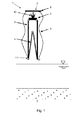
- FIGS. 1 to 6 1 shows a first variant of a base element 1, which can be lowered onto the bottom 3 of a sea below a water surface, for a stationary device 2 designed as a wind energy plant.
- the base element 1 is equipped with a bottom surface 4 which can be lowered onto the bottom 3 of the sea and which is connected to a base 5 supporting the device 2 by means of several supports 6.
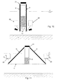
- a transport position is shown, in which the base element 1 by means of a transport device 7 comprising a ring traverse 8 and a realized by pulling means 9 hoist is held.
- the unwanted lowering of the base 5 is avoided by a connecting element 10, so that the load from the base 5 can be introduced directly into the ring traverse 8.
- the load is introduced by means of the hoist in the ring traverse 8, wherein the hoist is releasably fixed to the lower end portion 11 of the supports 6.
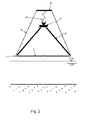
- the supports 6 spread under the influence of gravity, the supports 6 until the spanned between them floor surface 4 is taut.
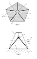
- FIG. 3 shows this working or use position in a plan view, in which the individual, the bottom surface 4 forming trapezoidal sheet materials 12 can be seen between the supports 6.
- FIG. 4 illustrates the already with the bottom surface 4 resting on the bottom 3 use position of the base element 1, in which the base 5 is well above the surface of the waterline 13.
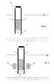
- the base element 1 may be equipped with a bag-shaped receptacle 14 of sediment, designed as a geotextile sack, as a weighting, which is aligned in the desired position by traction means 15. Such a position is in FIG. 5 to recognize.
- FIG. 6 is merely an example of a wind turbine as a device 2 shown.
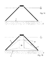
- FIGS. 7 to 16 a variant of a base element 16 is additionally shown, in which a crane for transport and positioning of the base element 16 can be dispensed with.
- the basic element 16, which in the FIGS. 1 to 6 shown constructive structure partially corresponds, with a one of the base 5 facing first chamber 17 and the bottom surface 4 facing the second chamber 18 existing buoyancy element 19 equipped.
- the two chambers 17, 18 are filled during transport with air and thereby generate sufficient for the buoyancy of the base member 16 buoyancy.
- the second chamber 18 is slowly flooded when reaching the target position, so that the remaining buoyancy of the first chamber 17 leads to a basic element 16 righting torque.
- FIG. 8 a corresponding vertical, floating position of the base member 16 is shown.
- the supports 6 are connected at their bottom surface 4 facing end portions 11 each with a buoyancy element 20, which is slowly filled with air and thus produces an increasing buoyancy F A.
- the supports 6, which are connected to the base 5 by means of a joint 21, execute a pivoting movement until the surface material 12 forming the bottom surface 4 is tensioned between the supports 6.
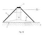
- the lowering to the bottom 3 is then initiated by also the second chamber 18 is slowly flooded until the base member 16 drops under the influence of its own weight on the bottom 3.
- the buoyancy elements 19, 20 are dimensioned for this purpose so that their buoyancy force F A is less than the weight of the base member 16 and therefore they are removed only after successful positioning on the bottom 3, as shown in the FIGS. 14 to 16 can be seen.
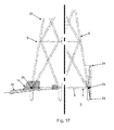
- FIGS Figures 17 and 18 show a base element 22 based on a hexagonal geometry with a plurality of supports 6 constructed of steel tubes. External force effects are derived by means of a system of cross struts, which pass through Rings are held together. The grid construction formed therefrom distributes the loads so effectively that comparatively thin-walled steel tubes can be used.
- the base element 22 is equipped with a bottom surface 4, which has several ground anchors 23 designed as ramming piles for improved fastening. Due to the small diameter, only very low noise emissions occur during hammering.
- the bottom surface 4 which is constructed from a sheet material 12 of the material group of the so-called geotextiles.
- the surface material 12 used here is permeable to water or else to the root system of grasses and other plants, but impermeable to sediment, sand or other solids of defined grain sizes. Plants also support the solidification of very soft water-containing soils and sludge or the separation of the water.
- Significant advantages of the geotextile sheet material 12 are the possibility for individual adaptation to different purposes and in the modular extensibility.
- fold-out frame 24 are provided on the sides of the base element 22 for this purpose. These are pivotally mounted on joints 25, which are attached to the lower ring traverse 8.
- the frame 24 are covered with the textile fabric as sheet material 12, which has a high strength, but does not have to be taut.
- the frames 24 are shaped so that they continue on the inner side of the Ringtraverse 8.
- the covered by the base element 22 base is thus increased by a multiple. Ensuring that the surface materials 12 of the frame covering are so that they are permeable to water, but can not be penetrated by sand or mud, it is ensured that the water movements in the course of the installation process and later incoming ocean currents can not cause Auskolken.
- the installation process is for this purpose carried out as follows: First, the base member 22 is lowered by a crane ship with still folded frame 24, 26 to the seabed. The process is interrupted shortly before reaching the seabed. The locking of the frame 24, 26 is then released and the frame 24, 26 fold by their own weight and possibly supported by a spring element, not shown, and thus reach the predetermined position. Subsequently, the base element 22 is deposited on the seabed. The base member 22 penetrates with the ground anchors 23 in the bottom 3 until the frames 24, 26 rest on the seabed. The bottom surface 4 lies with its surface material 12 on the cover layer of the seabed.
- the base member 22 is finally aligned by a not shown Rüttler head is placed specifically on too far upstanding corners on the lower Fundamentring and acts on these until the desired sinking depth is reached.
- the specific for receiving the sediment pocket-shaped receptacles 14 are filled by sand pumps via hoses. The water contained in the purged sand penetrates through the pores of the fabric-like textile sheet material 12 to the outside. Additional sediment and sand is distributed over the layers of sheet material 1 inside and outside the foundation ring to form a cover layer. The primitive 22 will now be left alone for a while until it finally settles.
- the vibrator When re-checking with a smaller work vessel, the vibrator can be used again if necessary to carry out further corrections.
- the flushed-in sediment and sand are so far removed from the water after the setting phase that they form a compact mass. This substantially reduces a conceivable tendency of the base element 22 to plastically deform under external influence. Over time, additional sand deposits on top of sheet material 12 due to the prevailing tidal flows.
- such offshore base elements 22 similar to artificial reefs the settlement of shells and also encourage fish. This tendency can be promoted by the targeted settlement of mussels or oysters, which can form with their biological adhesives after a short time another cover layer and so can contribute significantly to the strength of the arrangement.
- the sunk into the seabed frame parts are coated to protect against external influences in their preparation with an insulating plastic compound.
- the surrounding sediment prevents direct contact with moving water, which could lead to corrosion by the supply of oxygen.
Landscapes
- Engineering & Computer Science (AREA)
- Life Sciences & Earth Sciences (AREA)
- General Life Sciences & Earth Sciences (AREA)
- Mining & Mineral Resources (AREA)
- Paleontology (AREA)
- Civil Engineering (AREA)
- General Engineering & Computer Science (AREA)
- Structural Engineering (AREA)
- Revetment (AREA)
- Wind Motors (AREA)
Applications Claiming Priority (2)
| Application Number | Priority Date | Filing Date | Title |
|---|---|---|---|
| DE102012007569 | 2012-04-14 | ||
| DE102012106432 | 2012-07-17 |
Publications (2)
| Publication Number | Publication Date |
|---|---|
| EP2650445A2 true EP2650445A2 (fr) | 2013-10-16 |
| EP2650445A3 EP2650445A3 (fr) | 2017-03-15 |
Family
ID=48184122
Family Applications (1)
| Application Number | Title | Priority Date | Filing Date |
|---|---|---|---|
| EP13401035.4A Withdrawn EP2650445A3 (fr) | 2012-04-14 | 2013-04-10 | Elément de base pouvant être abaissé au niveau de la mer pour des dispositifs fixes |
Country Status (1)
| Country | Link |
|---|---|
| EP (1) | EP2650445A3 (fr) |
Citations (1)
| Publication number | Priority date | Publication date | Assignee | Title |
|---|---|---|---|---|
| EP2204497A1 (fr) | 2008-12-03 | 2010-07-07 | Overdick GmbH & co. KG | Procédé destiné à l'installation d'un agencement offshore flottant et agencement offshore flottant |
Family Cites Families (1)
| Publication number | Priority date | Publication date | Assignee | Title |
|---|---|---|---|---|
| WO2008036934A2 (fr) * | 2006-09-21 | 2008-03-27 | Ahmed Phuly | Système de fondation modulaire partiellement préfabriqué |
-
2013
- 2013-04-10 EP EP13401035.4A patent/EP2650445A3/fr not_active Withdrawn
Patent Citations (1)
| Publication number | Priority date | Publication date | Assignee | Title |
|---|---|---|---|---|
| EP2204497A1 (fr) | 2008-12-03 | 2010-07-07 | Overdick GmbH & co. KG | Procédé destiné à l'installation d'un agencement offshore flottant et agencement offshore flottant |
Also Published As
| Publication number | Publication date |
|---|---|
| EP2650445A3 (fr) | 2017-03-15 |
Similar Documents
| Publication | Publication Date | Title |
|---|---|---|
| EP2423390B1 (fr) | Module pivotant pour utilisation lors de l'établissement d'une fondation sous-marine d'une construction | |
| EP2360373B1 (fr) | Installation offshore, fondation d'une installation offshore et procédé d'établissement d'une installation offshore | |
| EP2753765B1 (fr) | Construction de fondation, destinée à être installée de façon silencieuse, d'une installation en mer, en particulier d'une éolienne en mer et procédé de montage associé | |
| EP2036814B1 (fr) | Squelette métallique destiné au montage de fondations sous-marines | |
| DE102010020995B4 (de) | Gründungssystem für die Gründung einer Offshore-Windenergieanlage | |
| DE10101405A1 (de) | Off-Shore-Windkraftanlage | |
| EP1876093A1 (fr) | Fondation offshore flottante et procédé de son réalisation | |
| DE2345274A1 (de) | Hebbare hochseeplattform | |
| EP2591176B1 (fr) | Installation en mer, en particulier éolienne | |
| EP3428345A1 (fr) | Fondation pour une éolienne en mer | |
| EP3012183A1 (fr) | Ancre a ventouse | |
| WO2018054532A1 (fr) | Ouvrage destiné à être érigé à la surface d'étendues d'eau et procédé pour son érection | |
| WO2016177783A1 (fr) | Ancre-poids flottante permettant d'ancrer une structure porteuse flottant en pleine mer à une éolienne, une station-service ou une station de conversion | |
| EP2955277B1 (fr) | Structure de fondation pour installations offshore, en particulier eoliennes | |
| EP2893086A2 (fr) | Fondation offshore et procédé de construction | |
| DE102007002314A1 (de) | Installation von Offshore-Windenergieanlagen | |
| DE102010046732A1 (de) | Verfahren zum Einbau eines Schwergewichtsfundaments für eine Offshore-Anlage, insbesondere eine WEA und Schwergewichtsfundament | |
| DE202010010094U1 (de) | Gründungssystem für die Gründung einer Offshore-Windenergieanlage | |
| DE102011012450A1 (de) | Verfahren zum Einbau eines Schwergewichtsgründungssystems für eine Offshore-Windenergieanlage (WEA) | |
| DE102011102546A1 (de) | Fundament für eine Offshore-Windenergieanlage | |
| DE102012218285A1 (de) | Vorrichtung und Verfahren zum Erstellen einer Gründung und Gründung | |
| DE102011106043A1 (de) | Transportverfahren für Windenergieanlagen auf See | |
| DE102012000268B4 (de) | Offshore-Windkraftanlage und Verfahren zur Errichtung der Offshore-Windkraftanlage | |
| DE102010006458A1 (de) | Verfahren und Installationsanordnung mit einer Flachgründung | |
| DE102012016692A1 (de) | Verfahren zum Einbau eines Schwergewichtsgründungssystems für eine Offshore-Windenergienanlage (WEA) |
Legal Events
| Date | Code | Title | Description |
|---|---|---|---|
| PUAI | Public reference made under article 153(3) epc to a published international application that has entered the european phase |
Free format text: ORIGINAL CODE: 0009012 |
|
| AK | Designated contracting states |
Kind code of ref document: A2 Designated state(s): AL AT BE BG CH CY CZ DE DK EE ES FI FR GB GR HR HU IE IS IT LI LT LU LV MC MK MT NL NO PL PT RO RS SE SI SK SM TR |
|
| AX | Request for extension of the european patent |
Extension state: BA ME |
|
| PUAL | Search report despatched |
Free format text: ORIGINAL CODE: 0009013 |
|
| AK | Designated contracting states |
Kind code of ref document: A3 Designated state(s): AL AT BE BG CH CY CZ DE DK EE ES FI FR GB GR HR HU IE IS IT LI LT LU LV MC MK MT NL NO PL PT RO RS SE SI SK SM TR |
|
| AX | Request for extension of the european patent |
Extension state: BA ME |
|
| RIC1 | Information provided on ipc code assigned before grant |
Ipc: E02D 27/52 20060101ALI20170207BHEP Ipc: E02D 17/02 20060101AFI20170207BHEP |
|
| STAA | Information on the status of an ep patent application or granted ep patent |
Free format text: STATUS: THE APPLICATION HAS BEEN PUBLISHED |
|
| STAA | Information on the status of an ep patent application or granted ep patent |
Free format text: STATUS: THE APPLICATION IS DEEMED TO BE WITHDRAWN |
|
| 18D | Application deemed to be withdrawn |
Effective date: 20170916 |